CN202949099U - Portable low voltage electricity testing indicating plug - Google Patents
Portable low voltage electricity testing indicating plug Download PDFInfo
- Publication number
- CN202949099U CN202949099U CN 201220637203 CN201220637203U CN202949099U CN 202949099 U CN202949099 U CN 202949099U CN 201220637203 CN201220637203 CN 201220637203 CN 201220637203 U CN201220637203 U CN 201220637203U CN 202949099 U CN202949099 U CN 202949099U
- Authority
- CN
- China
- Prior art keywords
- power supply
- emitting diode
- power
- low voltage
- supply plug
- Prior art date
- Legal status (The legal status is an assumption and is not a legal conclusion. Google has not performed a legal analysis and makes no representation as to the accuracy of the status listed.)
- Expired - Fee Related
Links
- 230000005611 electricity Effects 0.000 title abstract description 7
- 238000012795 verification Methods 0.000 claims description 5
- 238000010586 diagram Methods 0.000 description 1
- 230000000694 effects Effects 0.000 description 1
- 238000009413 insulation Methods 0.000 description 1
- 230000001681 protective effect Effects 0.000 description 1
Images
Landscapes
- Details Of Connecting Devices For Male And Female Coupling (AREA)
Abstract
The utility model relates to a portable low voltage electricity testing indicating plug, which comprises a power supply plug cap and power supply plug pins, wherein the power supply plug pins are arranged on the lower end of the power supply plug cap, a dropping resistor and a light emitting diode are connected between the two power supply plug pins in series, the dropping resistor is arranged in the power supply plug cap, and the light emitting diode is arranged on the upper end of the power supply plug cap. The portable low voltage electricity testing indicating plug can effectively test whether a work power supply has electricity, can be used as power supply indication, and is extremely convenient, rapid, safe and reliable to work.
Description
Technical field
The utility model relates to a kind of portable quick formula low pressure electrical verification indicating plug.
Background technology
At present, no matter be scene or laboratory, the reference instrument that uses or tested reference instrument, the power supply that adopts is single phase alternating current (A.C.) 220V, when working especially at the scene when in work, the instrument that sometimes uses is suddenly without showing, at this moment, do not know that power supply is out of joint without electricity or instrument power source part, thereby affected normal operation.
The utility model content
Technical problem to be solved in the utility model is to provide a kind ofly can verify effectively whether working power has electricity, and can be used as the portable quick formula low pressure electrical verification indicating plug of power supply indication.
The technical solution of the utility model is as follows:
The utility model comprises power plug head cap and the power pin that is arranged on power plug head cap lower end, a dropping resistor of series connection and a light-emitting diode between described two power pins, described dropping resistor is arranged on the inside of power plug head cap, and described light-emitting diode is arranged on the upper end of power plug head cap.
Good effect of the present utility model is as follows: at present, no matter be scene or laboratory, the reference instrument that uses or tested reference instrument, the power supply that adopts is single phase alternating current (A.C.) 220V, when working especially at the scene when in work, the instrument that sometimes uses is suddenly without showing, at this moment, do not know that power supply is out of joint without electricity or instrument power source part, thereby affected normal operation.The utility model not only can carry out electrical verification, the more important thing is and can also indicate as power supply.The utility model does not have dividing of both positive and negative polarity, as long as power supply is charged, how pin inserts light-emitting diode all can be bright, therefore, works together very convenient, quick, safe, reliable.
In addition, function and efficacy of the present utility model also can use in family life.
Description of drawings
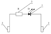
Accompanying drawing 1 is the utility model structural representation;
Accompanying drawing 2 is the utility model circuit theory diagrams.
In the accompanying drawings: 1 light-emitting diode, 2 power pins, 3 dropping resistors, 4 power plug head caps.
Embodiment
As shown in Figure 1, the power pin 2 that the utility model comprises power plug head cap 4 and is arranged on power plug head cap 4 lower ends, a dropping resistor 3 of series connection and a light-emitting diode 1 between two power pins 2, dropping resistor 3 is arranged on the inside of power plug head cap 4, and light-emitting diode 1 is arranged on the upper end of power plug head cap 4.
The utility model can be arranged in bifoot type single phase alternating current (A.C.) 220V attaching plug according to actual conditions; also can be arranged in tripod (wherein a pin is protective earthing) formula single phase alternating current (A.C.) 220V attaching plug; dropping resistor 3 is 153.5K; light-emitting diode 1 is 3V, and when power supply is charged, light-emitting diode is red.
As shown in accompanying drawing 1,2, concrete wiring is that one of dropping resistor 3 is terminated on a power pin 2 of attaching plug, and the other end is received the positive pole of light-emitting diode 1, and light-emitting diode 1 negative pole is received on another power pin 2 of attaching plug.
The utility model light-emitting diode 1 two ends, and dropping resistor 3 must package with the high temperature insulation sleeve pipe, to prevent the generation of short circuit phenomenon.
Claims (1)
1. portable quick formula low pressure electrical verification indicating plug, it is characterized in that the power pin (2) that it comprises power plug head cap (4) and is arranged on power plug head cap (4) lower end, a series connection dropping resistor (3) and a light-emitting diode (1) between described two power pins (2), described dropping resistor (3) is arranged on the inside of power plug head cap (4), and described light-emitting diode (1) is arranged on the upper end of power plug head cap (4).
Priority Applications (1)
| Application Number | Priority Date | Filing Date | Title |
|---|---|---|---|
| CN 201220637203 CN202949099U (en) | 2012-11-28 | 2012-11-28 | Portable low voltage electricity testing indicating plug |
Applications Claiming Priority (1)
| Application Number | Priority Date | Filing Date | Title |
|---|---|---|---|
| CN 201220637203 CN202949099U (en) | 2012-11-28 | 2012-11-28 | Portable low voltage electricity testing indicating plug |
Publications (1)
| Publication Number | Publication Date |
|---|---|
| CN202949099U true CN202949099U (en) | 2013-05-22 |
Family
ID=48424780
Family Applications (1)
| Application Number | Title | Priority Date | Filing Date |
|---|---|---|---|
| CN 201220637203 Expired - Fee Related CN202949099U (en) | 2012-11-28 | 2012-11-28 | Portable low voltage electricity testing indicating plug |
Country Status (1)
| Country | Link |
|---|---|
| CN (1) | CN202949099U (en) |
Cited By (8)
| Publication number | Priority date | Publication date | Assignee | Title |
|---|---|---|---|---|
| CN104953319A (en) * | 2015-06-24 | 2015-09-30 | 冯双喜 | Male tab adjustable plug |
| CN104953398A (en) * | 2015-06-29 | 2015-09-30 | 冯双喜 | Plug provided with electricity tester |
| CN104966965A (en) * | 2015-06-29 | 2015-10-07 | 冯双喜 | Improved plug |
| CN104966954A (en) * | 2015-06-29 | 2015-10-07 | 冯双喜 | Safety plug |
| CN104979728A (en) * | 2015-06-24 | 2015-10-14 | 冯双喜 | Novel plug |
| CN104979666A (en) * | 2015-06-24 | 2015-10-14 | 冯双喜 | Rotatable plug |
| CN105048218A (en) * | 2015-06-15 | 2015-11-11 | 冯双喜 | Plug facilitating storage |
| CN105048194A (en) * | 2015-06-29 | 2015-11-11 | 冯双喜 | Power plug with handle |
-
2012
- 2012-11-28 CN CN 201220637203 patent/CN202949099U/en not_active Expired - Fee Related
Cited By (8)
| Publication number | Priority date | Publication date | Assignee | Title |
|---|---|---|---|---|
| CN105048218A (en) * | 2015-06-15 | 2015-11-11 | 冯双喜 | Plug facilitating storage |
| CN104953319A (en) * | 2015-06-24 | 2015-09-30 | 冯双喜 | Male tab adjustable plug |
| CN104979728A (en) * | 2015-06-24 | 2015-10-14 | 冯双喜 | Novel plug |
| CN104979666A (en) * | 2015-06-24 | 2015-10-14 | 冯双喜 | Rotatable plug |
| CN104953398A (en) * | 2015-06-29 | 2015-09-30 | 冯双喜 | Plug provided with electricity tester |
| CN104966965A (en) * | 2015-06-29 | 2015-10-07 | 冯双喜 | Improved plug |
| CN104966954A (en) * | 2015-06-29 | 2015-10-07 | 冯双喜 | Safety plug |
| CN105048194A (en) * | 2015-06-29 | 2015-11-11 | 冯双喜 | Power plug with handle |
Similar Documents
| Publication | Publication Date | Title |
|---|---|---|
| CN202949099U (en) | Portable low voltage electricity testing indicating plug | |
| CN102707185B (en) | 2M cable tester | |
| CN202854270U (en) | Circuit testing apparatus for signal transmission line | |
| CN202929127U (en) | Circuit for detecting three-phase electricity phase sequence and open phase | |
| CN202956463U (en) | Secure on-off pen | |
| CN203350393U (en) | Communication cable testing device | |
| CN202676340U (en) | Relay contact pressure detection mechanism | |
| CN202720516U (en) | Remote control outlet detector of circuit breaker | |
| CN203551645U (en) | Novel multifunctional test pencil | |
| CN203054106U (en) | Relay-protection tripping matrix tester | |
| CN201242741Y (en) | Rapid detection/regulation device for USB | |
| CN201993451U (en) | Switching power supply maintenance detector | |
| CN203881879U (en) | On-off state and polarity test tool | |
| CN204203418U (en) | LED tests tweezer | |
| CN205656267U (en) | Polarity tester for portable current transformers | |
| CN205714551U (en) | Test device for motor cycle ignitor | |
| CN203181322U (en) | Intelligent self-check device for LED lamps | |
| CN203732714U (en) | Test tool for carrier module of electric energy meter | |
| CN104267308A (en) | Fast detector for access circuit and open circuit | |
| CN204719123U (en) | A kind of overvoltage undervoltage detection circuit | |
| CN202434822U (en) | Socket for electric quantity metering | |
| CN201515112U (en) | Socket with creepage indication | |
| CN203405533U (en) | Pollution flashover monitoring device | |
| CN201749181U (en) | Simple polarity tester | |
| CN203398785U (en) | Switching switch controller |
Legal Events
| Date | Code | Title | Description |
|---|---|---|---|
| C14 | Grant of patent or utility model | ||
| GR01 | Patent grant | ||
| CF01 | Termination of patent right due to non-payment of annual fee |
Granted publication date: 20130522 Termination date: 20161128 |
|
| CF01 | Termination of patent right due to non-payment of annual fee |