CN202884121U - Change-over valve - Google Patents
Change-over valve Download PDFInfo
- Publication number
- CN202884121U CN202884121U CN2012204221688U CN201220422168U CN202884121U CN 202884121 U CN202884121 U CN 202884121U CN 2012204221688 U CN2012204221688 U CN 2012204221688U CN 201220422168 U CN201220422168 U CN 201220422168U CN 202884121 U CN202884121 U CN 202884121U
- Authority
- CN
- China
- Prior art keywords
- plunger
- wall
- water outlet
- sleeve
- sealing
- Prior art date
- Legal status (The legal status is an assumption and is not a legal conclusion. Google has not performed a legal analysis and makes no representation as to the accuracy of the status listed.)
- Expired - Fee Related
Links
Images


Classifications
-
- F—MECHANICAL ENGINEERING; LIGHTING; HEATING; WEAPONS; BLASTING
- F16—ENGINEERING ELEMENTS AND UNITS; GENERAL MEASURES FOR PRODUCING AND MAINTAINING EFFECTIVE FUNCTIONING OF MACHINES OR INSTALLATIONS; THERMAL INSULATION IN GENERAL
- F16K—VALVES; TAPS; COCKS; ACTUATING-FLOATS; DEVICES FOR VENTING OR AERATING
- F16K1/00—Lift valves or globe valves, i.e. cut-off apparatus with closure members having at least a component of their opening and closing motion perpendicular to the closing faces
- F16K1/32—Details
- F16K1/34—Cutting-off parts, e.g. valve members, seats
-
- F—MECHANICAL ENGINEERING; LIGHTING; HEATING; WEAPONS; BLASTING
- F16—ENGINEERING ELEMENTS AND UNITS; GENERAL MEASURES FOR PRODUCING AND MAINTAINING EFFECTIVE FUNCTIONING OF MACHINES OR INSTALLATIONS; THERMAL INSULATION IN GENERAL
- F16K—VALVES; TAPS; COCKS; ACTUATING-FLOATS; DEVICES FOR VENTING OR AERATING
- F16K11/00—Multiple-way valves, e.g. mixing valves; Pipe fittings incorporating such valves
- F16K11/02—Multiple-way valves, e.g. mixing valves; Pipe fittings incorporating such valves with all movable sealing faces moving as one unit
- F16K11/04—Multiple-way valves, e.g. mixing valves; Pipe fittings incorporating such valves with all movable sealing faces moving as one unit comprising only lift valves
- F16K11/048—Multiple-way valves, e.g. mixing valves; Pipe fittings incorporating such valves with all movable sealing faces moving as one unit comprising only lift valves with valve seats positioned between movable valve members
-
- E—FIXED CONSTRUCTIONS
- E03—WATER SUPPLY; SEWERAGE
- E03C—DOMESTIC PLUMBING INSTALLATIONS FOR FRESH WATER OR WASTE WATER; SINKS
- E03C2201/00—Details, devices or methods not otherwise provided for
- E03C2201/30—Diverter valves in faucets or taps
-
- Y—GENERAL TAGGING OF NEW TECHNOLOGICAL DEVELOPMENTS; GENERAL TAGGING OF CROSS-SECTIONAL TECHNOLOGIES SPANNING OVER SEVERAL SECTIONS OF THE IPC; TECHNICAL SUBJECTS COVERED BY FORMER USPC CROSS-REFERENCE ART COLLECTIONS [XRACs] AND DIGESTS
- Y10—TECHNICAL SUBJECTS COVERED BY FORMER USPC
- Y10T—TECHNICAL SUBJECTS COVERED BY FORMER US CLASSIFICATION
- Y10T137/00—Fluid handling
- Y10T137/2496—Self-proportioning or correlating systems
- Y10T137/2559—Self-controlled branched flow systems
- Y10T137/265—Plural outflows
- Y10T137/2668—Alternately or successively substituted outflow
- Y10T137/268—Responsive to pressure or flow interruption
- Y10T137/2683—Plural outlets control with automatic reset
-
- Y—GENERAL TAGGING OF NEW TECHNOLOGICAL DEVELOPMENTS; GENERAL TAGGING OF CROSS-SECTIONAL TECHNOLOGIES SPANNING OVER SEVERAL SECTIONS OF THE IPC; TECHNICAL SUBJECTS COVERED BY FORMER USPC CROSS-REFERENCE ART COLLECTIONS [XRACs] AND DIGESTS
- Y10—TECHNICAL SUBJECTS COVERED BY FORMER USPC
- Y10T—TECHNICAL SUBJECTS COVERED BY FORMER US CLASSIFICATION
- Y10T137/00—Fluid handling
- Y10T137/8593—Systems
- Y10T137/86493—Multi-way valve unit
- Y10T137/86879—Reciprocating valve unit
- Y10T137/86895—Plural disk or plug
-
- Y—GENERAL TAGGING OF NEW TECHNOLOGICAL DEVELOPMENTS; GENERAL TAGGING OF CROSS-SECTIONAL TECHNOLOGIES SPANNING OVER SEVERAL SECTIONS OF THE IPC; TECHNICAL SUBJECTS COVERED BY FORMER USPC CROSS-REFERENCE ART COLLECTIONS [XRACs] AND DIGESTS
- Y10—TECHNICAL SUBJECTS COVERED BY FORMER USPC
- Y10T—TECHNICAL SUBJECTS COVERED BY FORMER US CLASSIFICATION
- Y10T137/00—Fluid handling
- Y10T137/8593—Systems
- Y10T137/877—With flow control means for branched passages
- Y10T137/87829—Biased valve
- Y10T137/87837—Spring bias
- Y10T137/87861—Spring coaxial with valve
Landscapes
- Engineering & Computer Science (AREA)
- General Engineering & Computer Science (AREA)
- Mechanical Engineering (AREA)
- Nozzles (AREA)
Abstract
The utility model discloses a change-over valve which comprises a sleeve, a cylinder-shaped plunger which moves axially in the sleeve and a vibration relief spring which is arranged between the sleeve and the plunger. Two seal rings are respectively arranged at two ends of the plunger, the plunger can be sealed with one of two seal surfaces in the sleeve when moving so that water currents which flow into the change-over valve are led to a tap exit or a nozzle. Multiple retaining blocks and flow enhancing gaps among all retaining blocks are arranged on a joint between the plunger and a first seal surface so as to ensure that quantity of conducted water is ensured, the opposite seal rings can be prevented from deformation under water pressure so as to avoid leak. Multiple guide sliding ribs and flow guiding grooves among all guide sliding ribs are arranged on the circumference of the plunger so that on one hand, water can smoothly flow by and on the other hand, the function of guiding sliding can prevent swing when the plunger moves. The vibration relief spring and a water flow conducting opening can prevent the plunger from vibrating and consequentially generating noise when a water outflow mode is changed over.
Description
Technical field
The utility model relates to a kind of for current are converted to the changing valve of another outlet from an outlet, especially is fit to be installed on the faucet assembly of tool shower nozzle effluent functions.
Background technique
Installation is applied to the changing valve on the faucet assembly of side tool shower nozzle, can be with Waterflow-guiding to tap outlet or along flexible pipe to shower nozzle, and be well-known technology.In the ordinary course of things, when the handle on the faucet assembly was unlocked, current can be directed to tap outlet by changing valve and flow out the formation tap water outlet; When the handle on the shower nozzle is operated, because the changing valve inside water pressure can along with change, flow out the water outlet of formation shower nozzle and flow direction-changing is directed to shower nozzle.Above-mentioned current are mixed by the cold water of a cold water pipeline and a hot water pipe's hot water usually, the ratio of mixing can be controlled by single handle start one mixing valve that is positioned on the faucet assembly, also can by a cold water handle and hot water handle is controlled respectively a cold valves and a water valve is controlled.
China Patent No. ZL200480016737.7 utility model patent has disclosed a kind of side spray diverter valve, can be installed in the valve body of a faucet assembly, and include a sleeve and can be along sleeve plunger in axial sliding.Under normal circumstances, by entering the current of plunger behind the sleeve, can from the gap of the upper O shape ring of plunger top and upper valve base, pass through, and flow to tap outlet.When the handle on the shower nozzle is operated, because of the hydraulic pressure in the changing valve along with change, plunger is axial slip down, make O shape ring support the sealing upper valve base, to stop tap water outlet, simultaneously, by the current of sleeve, can pass through with the gap of lower valve base from lower O shape ring, and flow to shower nozzle.
There is the following point point in the changing valve of above-mentioned patent:
At first, though its plunger can be fitted by plunger wall outer surface and sleeve inner circle wall, produce beat when preventing the plunger slippage, but also force plunger must adopt the hollow shape design, in order to can form in inside a chamber and around chamber, form two groups of plunger ports that supply water and flow to out.As everyone knows, chamber and plunger ports structure will make plunger produce puzzlement in metal forming and manufacturing, particularly high processing cost like this.
Secondly, although the upper O shape ring of plunger can be supported the sealing upper valve base, faucet assembly is changed formed the shower nozzle water outlet, yet, because upper O shape ring under long high Water Pressure, produces distortion easily, therefore, cause producing easily the gap between itself and upper valve base, cause under the state of shower nozzle water outlet, tap outlet still has leakage phenomenon.
Moreover, when water exit mode converts the shower nozzle water outlet to from tap water outlet, because of differential pressure action, plunger can move towards shower nozzle water outlet direction rapidly, because this changing valve does not have the vibration damping structure design, therefore, cause the upper O shape ring moment bump upper valve base of plunger, cause transfer process to be accompanied by vibrating noise.
In addition, when faucet assembly converts tap water outlet to from the shower nozzle water outlet, because tap outlet is provided with the energy-conservation Water wave forming device of tool usually, therefore, can make water flow moment generation back pressure that diminishes, cause plunger to move towards shower nozzle water outlet and the continuous conversion of tap water outlet direction in moment, and form jitter phenomenon.In like manner, when intake pressure is unstable, also can cause the plunger shake.
The model utility content
The utility model main purpose is to provide a kind of changing valve, can effectively reduce production costs and improve the spare part yield, stability and smoothness in the time of can guaranteeing again the water exit mode conversion, prevent that transfer process from producing shake, vibration, vibration behaviour sound, and avoid affecting stable water outlet and backsiphonage usefulness.Simultaneously, can guarantee uninterrupted and the stability of tap water outlet or shower nozzle water outlet.
For reaching above-mentioned purpose, the utility model provides a kind of changing valve, comprising:
One sleeve is cylindric, and has a relative tap water outlet end and a shower nozzle waterexit end, and comprises a surrounding wall wall and be connected in one side sidewall wall of described surrounding wall wall one end, and described avris wall wall is positioned at described shower nozzle waterexit end; Jointly define between described surrounding wall wall and avris wall wall a diameter minimum the inner passage, be communicated in described passage and with respect to the first water outlet chamber of described tap water outlet end, and be communicated in described passage and with respect to the second water outlet chamber of described shower nozzle waterexit end; Described surrounding wall wall is formed with one first valve seat at described passage and the first water outlet chamber intersection, is formed with one second valve seat at described passage and the second water outlet chamber intersection, forms at least one water intake in described passage middle section; Described the first valve seat has and is cone shape one first sealing surfaces, and from a plurality of blocks that described the first sealing surfaces distributes towards described the first water outlet chamber axis of orientation to isogonism and extends, respectively define an incremental gap that can supply current to pass through thus between described wantonly two adjacent blocks; Described the second valve seat has and is cone shape one second sealing surfaces;
One plunger is cylindric, and is extended through the passage of described sleeve, and has one first relative sealing position and one second sealing position; Be provided with one first sealing ring on described the first sealing position, can when move described shower nozzle waterexit end, support at described plunger the first sealing surfaces of described the first valve seat of sealing, and can be by described the first sealing ring radial expanding deformation oil of described stop limits; Be provided with one second sealing ring on described the second sealing position, can when described tap water outlet end moves, support at described plunger the second sealing surfaces of described the second valve seat of sealing; Described plunger is formed with the slide guide rib that a plurality of isogonisms distribute at the periphery wall of described the first sealing position and the second sealed department interdigit, the outer wall of described slide guide rib respectively is formed with slide guide surface, in order to the mutual slippage of passage inner circle wall of described sleeve, when moving axially, produce beat and can limit described plunger, and described wantonly two adjacent slide guide intercostals respectively define a guiding gutter that extends vertically and are communicated in described water intake, and are communicated with described the first water outlet chamber can break away from the first sealing ring of described plunger the first sealing surfaces of described sleeve the time;
One shock-absorbing spring is installed between the avris wall wall and described plunger opposite end of described sleeve, but its elastic-restoring force of mat is supported the second sealing ring of described plunger on the second sealing surfaces that is sealed in described sleeve.
Preferably, described sleeve is provided with four blocks.
Preferably, the first sealing position of described plunger is provided with one first annular groove, and it can be for the nested location of described the first sealing ring; Each guiding gutter of described plunger is connected with described the first annular groove with respect to an end of described the first annular groove.
Preferably, described plunger is provided with four slide guide ribs, and its horizontal section is crosswise.
Preferably, the slide guide of each slide guide rib of described plunger surface is 0.2 ~ 0.5mm with the girth ratio of described sleeve inner passage inner circle wall.
Preferably, the avris wall wall central authorities of described sleeve are provided with a current port and are communicated with described the second water outlet chamber, and described current port is circular hole, and its diameter is 2.5 ~ 5mm.
Preferably, the second sealing position of described plunger is provided with one second annular groove, and it can be for the nested location of described the second sealing ring; Described plunger is formed with certain ebb interval between the inner circle wall of a side periphery wall of the relatively described shower nozzle of described the second annular groove waterexit end and described the second water outlet chamber, described constant current gap is between 0.03 ~ 0.15mm.
Preferably, the relative distolateral spring locating slot that respectively is concaved with of the avris wall wall of described sleeve and described plunger can be supported the location for described shock-absorbing spring two ends.
Preferably, described sleeve is comprised of the capping that a sleeve body and buckle are positioned described sleeve body one side opening, and can form described avris wall wall by described capping.
Adopted changing valve of the present utility model, because plunger is adopted cylindrical design, thus help to manufacture and metal processing, and reduce production costs significantly, also can improve the yield of spare part.
The utility model can be by the guiding gutter design of the slide guide rib on the plunger and each slide guide intercostal, guarantee that on the one hand each guiding gutter allows enough current to lead to tap outlet, guarantee that on the other hand plunger can move on steady and smooth ground, and can not produce beat, and then affect stable water outlet and backsiphonage usefulness.
The utility model is by the design of the block of plunger, and the first sealing ring that can limit plunger is subject to Water Pressure when supporting sealing with sleeve the first sealing surfaces and produces dilatating and deformable, so can prevent tap outlet generation water leakage phenomenon.In addition, utilize the incremental gap between each block, also can improve the water-flowing amount between each guiding gutter and the first water outlet chamber, and then guarantee the flow of tap water outlet.
Shock-absorbing spring design of the present utility model can avoid plunger to produce shake, vibration and vibrating noise when water exit mode converts tap water outlet to by the shower nozzle water outlet, simultaneously, also can guarantee the stability of tap water outlet.
Constant current gap design of the present utility model, can be effectively with the flow control of shower nozzle water outlet in a certain size scope, and reach the effect of regime flow.
The utility model utilizes avris wall wall central position to design the current port in single and the pre-sizing of tool aperture, can prevent that the current that lead to the second water outlet chamber via the constant current gap from producing flow-disturbing or turbulent flow, and then plunger produces skew or jitter phenomenon.
Description of drawings
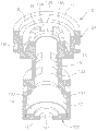
Fig. 1 is the outward appearance constitutional diagram of the utility model changing valve;
Fig. 2 is the three-dimensional exploded view of the utility model changing valve;
Fig. 3 is that Fig. 1 is along the side cutaway view of A-A hatching;
Fig. 4 is that Fig. 1 is along the side cutaway view of B-B hatching;
Fig. 5 is the three-dimensional cutaway view of the utility model sleeve;
Fig. 6 is the stereo appearance figure of the utility model plunger;
Fig. 7 is the streamflow regime schematic representation of the utility model changing valve when tap water outlet;
Fig. 8 is the streamflow regime schematic representation of the utility model changing valve when the shower nozzle water outlet;
Fig. 9 is the three-dimensional appearance constitutional diagram that the utility model changing valve is installed on the difunctional tap in kitchen.
[primary clustering symbol description]
1 changing valve
10 sleeves
102 cappings of 101 sleeve body
103 constant current gaps, 11 tap water outlet ends
12 shower nozzle waterexit ends, 13 surrounding wall walls
131 first valve seats, 132 second valve seats
133 water intakes, 134 first sealing surfaces
135 blocks, 136 incremental gaps
137 second sealing surfaces, 14 avris wall walls
141 current ports, 15 passages
16 first water outlet chambers, 17 second water outlet chambers
18 spring locating slots
20 plungers
21 first sealing positions, 211 first sealing rings
212 first annular grooves, 22 second sealing positions
221 second sealing rings, 222 second annular grooves
23 slide guide ribs, 231 slide guides surface
232 guiding gutters, 24 spring locating slots
30 shock-absorbing springs
40 faucet assemblies
41 leader shells, 411 outlet pipes
412 tap outlets, 42 cold water joints
43 hot water joints, 44 mixing valves
45 handles, 46 combustion tapss
47 flexible pipes, 48 shower nozzles
481 operating levers
The realization of the utility model purpose, functional characteristics and advantage are described further with reference to accompanying drawing in connection with embodiment.
Embodiment
Should be appreciated that specific embodiment described herein only in order to explaining the utility model, and be not used in restriction the utility model.
As shown in Figures 1 to 4, the utility model provides a kind of preferred embodiment of changing valve, and this changing valve 1 comprises a sleeve 10, a plunger 20 and a shock-absorbing spring 30; Wherein:
As shown in Figure 5, described sleeve 10 roughly is cylindric, and has a relative tap water outlet end 11 and a shower nozzle waterexit end 12, and comprise a surrounding wall wall 13 and be connected in one side sidewall wall 14 of described surrounding wall wall 13 1 ends, described avris wall wall 14 is positioned at described shower nozzle waterexit end 12.Described surrounding wall wall 13 and 14 on avris wall wall jointly define a diameter minimum inner passage 15, be communicated in described passage 15 and with respect to the first water outlet chamber 16 of described tap water outlet end 11, and be communicated in described passage 15 and with respect to the second water outlet chamber 17 of described shower nozzle waterexit end 12.Described surrounding wall wall 13 is formed with one first valve seat 131 at described passage 15 and the first water outlet chamber 16 intersections, be formed with one second valve seat 132 at described passage 15 and the second water outlet chamber 17 intersections, be formed with at least one water intake 133 in described passage 15 middle sections, present embodiment is provided with two groups of water intakes that separate vertically 133 altogether, the water intake 133 that each group has four circumferential isogonisms in edge to distribute.Described the first valve seat 131 has and is cone shape one first sealing surfaces 134, and a plurality of blocks 135 that distribute towards described the first water outlet chamber 16 axis of orientations to isogonism and extend from described the first sealing surfaces 134, and present embodiment is provided with four blocks 135.Described wantonly two 135 of adjacent blocks respectively define an incremental gap 136 that can supply current to pass through thus; Described the second valve seat 132 has and is cone shape one second sealing surfaces 137.Described incremental gap 136 main purposes are to improve and the reinforcement water amount.
Be convenient and manufacture that described sleeve 10 can be comprised of the capping 102 that a sleeve body 101 and buckle are positioned described sleeve body 101 1 side openings; Wherein, described sleeve 10 major parts are made of described sleeve body 101, and capping 102 mainly is to consist of described avris wall wall 14.
As shown in Figure 6, described plunger 20 roughly is cylindric, and is extended through the passage 15 of described sleeve 10, and has one first relative sealing position 21 and one second sealing position 22; Be provided with one first sealing ring 211 on described the first sealing position 21, can when moving, described shower nozzle waterexit end 12 support at described plunger 20 the first sealing surfaces 134 of described the first valve seat 131 of sealing, and can by described the first sealing ring of described block 135 restrictions 211 radial expanding deformation oils, use the maintenance excellent sealing effect.Be provided with one second sealing ring 221 on described the second sealing position 22, can when described tap water outlet end 11 moves, support at described plunger 20 the second sealing surfaces 137 of described the second valve seat 132 of sealing.Described plunger 20 is formed with the slide guide rib 23 that a plurality of isogonisms distribute at described the first sealing position 21 and the second periphery wall that seals 22 at position, and present embodiment is provided with four slide guide ribs 23 altogether, and its horizontal section is crosswise.Described slide guide rib 23 outer wall respectively are formed with a slide guide surface 231, in order to the mutual slippage of passage 15 inner circle walls of described sleeve 10, and then limit described plunger 20 and when moving axially, produce beat, and described wantonly two 23 adjacent in slide guide ribs respectively define a guiding gutter that extends vertically 232 and are communicated with described water intake 133, what can infer easily is, present embodiment has four guiding gutters 232 that isogonism is uniform, can be communicated with described the first water outlet chamber 16 when first of described plunger 20 seals the first sealing surfaces 134 of the described sleeve 10 of ring 211 disengagings.
The first sealing ring 211 of present embodiment and the second sealing ring 221 can be the O shape ring that quality of rubber materials is made, therefore, utilization arranges respectively one first annular groove 212 and one second annular groove 222 at the first sealing position 21 and the second sealing position 22 of described plunger 20, can be for above-mentioned the first sealing ring 211 and the second ring 221 nested location.
Should be noted, plunger 20 each guiding gutter 232 of present embodiment are connected with described the first annular groove 212 with respect to the end system of described the first annular groove 212, structural design like this, main purpose is: the moment that breaks away from the first sealing surfaces 134 when the first sealing ring 211, the current that enter in the guiding gutter 232 can flow to the first water outlet chamber 16 that is connected rapidly, simultaneously, when current pass through from the gap of the first sealing ring 211 and the first sealing surfaces 134, just can be by above-mentioned incremental gap 136 raisings of 135 of each blocks and the water-flowing amount that reinforcement enters the first water outlet chamber 16 of being positioned at.
The plunger 20 of present embodiment is the slide guide surface 231 and the mutual slippage of described sleeve 10 inner passages, 15 inner circle walls by each slide guide rib 23, guiding gutter 232 water supply streams by 23 in each slide guide rib pass through simultaneously, can be understood that easily, when the girth ratio of the overall circumference on above-mentioned slide guide surface 231 and passage 15 inner circle walls is excessive, can cause the water-flowing amount of guiding gutter 232 excessively low.On the contrary, when both ratio was too small, because the slide guide area is too small, the pressure that unit area is born improved relatively, produced easily wearing and tearing, and then affected the usefulness of working life and slide guide, so both desirable girth ratio systems are between 0.2 ~ 0.5.
The plunger 20 of present embodiment is formed with certain ebb interval 103 between a side periphery wall of the relatively described shower nozzle of described the second annular groove 222 waterexit end 12 and described the second water outlet chamber 17 inner circle walls, can use the control water-flowing amount in prespecified range, and can avoid water-flowing amount to produce obvious drop.The ideal value system in above-mentioned constant current gap 103 is between between 0.03 ~ 0.15mm.
Described shock-absorbing spring 30 is to be installed between the avris wall wall 14 and described plunger 20 opposite ends of described sleeve 10, but its elastic-restoring force of mat is supported the second sealing ring 221 of described plunger 20 on the second sealing surfaces 137 that is sealed in described sleeve 10.
Present embodiment is installed for convenient above-mentioned shock-absorbing spring 30, more respectively at the avris wall wall 14 of described sleeve 10 and the relative distolateral spring locating slot 18,24 that is arranged with of described plunger 20, supports the location for described shock-absorbing spring 30 2 ends.
As shown in Figure 9, changing valve 1 of the present utility model is particularly suitable for being installed in the Double-function tap assembly 40 for kitchen use, this faucet assembly 40 comprises a leader shell 41, its below is connected with a cold water joint 42 and a hot water joint 43, the hot water or cold water who comes from cold feed pipeline and hot water supply line can be sent to the mixing valve 44 in the leader shell 41, described mixing valve 44 can be subjected to a handle 45 that is installed on the leader shell 41 to open, cut out and regulate hot water or cold water's mixed proportion.When mixing valve 44 is unlocked, hot water or cold water or mixing water can be sent to changing valve 1 of the present utility model.Be formed with an outlet pipe 411 on the described leader shell 41, outlet pipe 411 ends are provided with a tap outlet 412, leader shell 41 belows are provided with a mixing water joint 46, in order to connect a flexible pipe 47, described flexible pipe 47 another ends then connect one and are installed on the faucet assembly 40, the shower nozzle 48 that can property pull selected by the user resets is provided with on the described shower nozzle 48 and is the operating lever 481 of closed condition under the normality.
Accordingly, as shown in Figure 7, after the current that come from mixing valve 44 flow into from changing valve 1 each water intake 133, can flow to the first water outlet chamber 16 along the incremental gap 136 of 135 of gap, sleeve 10 each blocks of the first sealing ring 211 of each guiding gutter 232, plunger 20 around the plunger 20 and sleeve 10 first sealing surfaces 134, flow to again tap outlet 412 formation tap water outlets.
Then, as shown in Figure 8, when the user presses operating lever 481 on the shower nozzle 48, the inside water pressure of described changing valve 1 can be along with change, cause plunger 20 to move axially toward shower nozzle waterexit end 12 directions, force the second sealing surfaces 137 of plunger 20 second sealing rings 221 moments disengaging sleeves 10, at this moment, enter the current of changing valve 1, just can be by the gap of the second sealing ring 221 and the second sealing surfaces 137, enter the second water outlet chamber 17 by above-mentioned constant current gap 103 again, then, flow to shower nozzle 48 via the current port 141 of avris wall wall 14 and form the shower nozzle water outlets.
What need special instruction is, the moment that breaks away from sleeve 10 second sealing surfaces 137 when the second sealing ring 221 of plunger 20, the first sealing ring 211 also can moment and the first sealing surfaces 134 of sleeve 10 mutually support sealing, flow to the current of tap water outlet end 11 with blocking-up, and then the cutout cock water outlet, so can successfully to the shower nozzle water outlet will be converted from tap water outlet.In like manner, when the user unclasped the operating lever 481 of shower nozzle 48, plunger 20 was moved toward tap water outlet end 11 by the hydraulic pressure change can again, converts shower nozzle 48 water outlets to tap water outlet.
As from the foregoing, the utility model is designed to the plunger 20 of changing valve 1 cylindric, owing to there is not known internal cavities, and the through-hole structure that is connected with cavity, so quite favourable for manufacturing with metal processing, can reduce significantly manufacture cost, improve the yield of spare part.
The utility model utilizes at plunger 20 design slide guide ribs 23, and the guiding gutter 232 that is positioned at 23 in each slide guide rib, can guarantee that on the one hand each guiding gutter 232 allows enough current to lead to tap outlet 412, can guarantee that on the other hand plunger 20 steady and smooth ground is mobile, and can not produce beat, and then affect flow stability and backsiphonage usefulness.
The utility model utilizes block 135 designs of plunger 20, the first sealing ring 211 that can limit plunger 20 is subject to Water Pressure when supporting sealing with sleeve 10 first sealing surfaces 134 and produces radial expanding deformation oil, so can guarantee sealing effect, prevent that tap outlet 412 from producing water leakage phenomenon.In addition, incremental gap 136 designs that above-mentioned block is 135 also can in time improve the water-flowing amount of 16 of each guiding gutter 232 and the first water outlet chambers, and then guarantee the flow of tap water outlet.
The utility model is by the elastic-restoring force of shock-absorbing spring 30, can convert tap water outlet to from the shower nozzle water outlet at water exit mode, when simultaneously current produce back pressure because of the Water wave forming device throttling action at tap outlet place, still the stability that keeps plunger 20, be subjected to this back pressure effect to produce shake, vibration and vibrating noise and be unlikely, guarantee simultaneously the stability of tap water outlet.In addition, this shock-absorbing spring 30 jitter phenomenon that also can produce because of the intake pressure shakiness in order to solve plunger 20.
The utility model utilizes formed constant current gap 103 between the periphery wall in plunger 20 second sealing rings 221 outsides and sleeve 10 second water outlet chambers 17 inner circle walls, because impact that can plunger 20 mobile positions, can keep at any time certain gap length, therefore, water-flowing amount can be controlled in certain magnitude range, and reach the effect of stabilize water flow.In other words, the water flow of shower nozzle water outlet, just can not be subject to the second sealing ring 221 and the second sealing surfaces 22 gap lengths move along with plunger 20 and change affect, so can avoid producing the suddenly big or suddenly small phenomenon of flow.
The utility model utilizes the current port 141 in the single and pre-sizing of avris wall wall 14 central positions design aperture, can prevent from flowing to the current of the second water outlet chamber 17 at the second water outlet chamber 17 interior generation flow-disturbing or turbulent flows via constant current gap 103 on the one hand, avoid plunger 20 opposite ends to be subjected to this flow-disturbing or action of turbulent flow to produce skew or shake, also can guarantee enough water-flowing amounts on the other hand.
In sum, the utility model has its splendid progress practicability in fact in like product, simultaneously all over the technical data of looking into both at home and abroad about this class formation, also find no identical structure in the document or manufacture method is present in elder generation, be with, the utility model is real to have possessed the utility model patent important document, files an application in accordance with the law.
Should be understood that; it below only is preferred embodiment of the present utility model; can not therefore limit claim of the present utility model; every equivalent structure or equivalent flow process conversion that utilizes the utility model specification and accompanying drawing content to do; or directly or indirectly be used in other relevant technical fields, all in like manner be included in the scope of patent protection of the present utility model.
Claims (9)
1. a changing valve is characterized in that, comprising:
One sleeve is cylindric, and has a relative tap water outlet end and a shower nozzle waterexit end, and comprises a surrounding wall wall and be connected in one side sidewall wall of described surrounding wall wall one end, and described avris wall wall is positioned at described shower nozzle waterexit end; Jointly define between described surrounding wall wall and avris wall wall a diameter minimum the inner passage, be communicated in described passage and with respect to the first water outlet chamber of described tap water outlet end, and be communicated in described passage and with respect to the second water outlet chamber of described shower nozzle waterexit end; Described surrounding wall wall is formed with one first valve seat at described passage and the first water outlet chamber intersection, is formed with one second valve seat at described passage and the second water outlet chamber intersection, forms at least one water intake in described passage middle section; Described the first valve seat has and is cone shape one first sealing surfaces, and from a plurality of blocks that described the first sealing surfaces distributes towards described the first water outlet chamber axis of orientation to isogonism and extends, respectively define an incremental gap that can supply current to pass through thus between described wantonly two adjacent blocks; Described the second valve seat has and is cone shape one second sealing surfaces;
One plunger is cylindric, and is extended through the passage of described sleeve, and has one first relative sealing position and one second sealing position; Be provided with one first sealing ring on described the first sealing position, can when move described shower nozzle waterexit end, support at described plunger the first sealing surfaces of described the first valve seat of sealing, and can be by described the first sealing ring radial expanding deformation oil of described stop limits; Be provided with one second sealing ring on described the second sealing position, can when described tap water outlet end moves, support at described plunger the second sealing surfaces of described the second valve seat of sealing; Described plunger is formed with the slide guide rib that a plurality of isogonisms distribute at the periphery wall of described the first sealing position and the second sealed department interdigit, the outer wall of described slide guide rib respectively is formed with slide guide surface, in order to the mutual slippage of passage inner circle wall of described sleeve, when moving axially, produce beat and can limit described plunger, and described wantonly two adjacent slide guide intercostals respectively define a guiding gutter that extends vertically and are communicated in described water intake, and are communicated with described the first water outlet chamber can break away from the first sealing ring of described plunger the first sealing surfaces of described sleeve the time;
One shock-absorbing spring is installed between the avris wall wall and described plunger opposite end of described sleeve, but its elastic-restoring force of mat is supported the second sealing ring of described plunger on the second sealing surfaces that is sealed in described sleeve.
2. changing valve according to claim 1 is characterized in that, described sleeve is provided with four blocks.
3. changing valve according to claim 1 is characterized in that, the first sealing position of described plunger is provided with one first annular groove, and it can be for the nested location of described the first sealing ring; Each guiding gutter of described plunger is connected with described the first annular groove with respect to an end of described the first annular groove.
4. changing valve according to claim 1 is characterized in that, described plunger is provided with four slide guide ribs, and its horizontal section is crosswise.
5. changing valve according to claim 1 is characterized in that, the slide guide surface of each slide guide rib of described plunger is 0.2 ~ 0.5mm with the girth ratio of described sleeve inner passage inner circle wall.
6. changing valve according to claim 1 is characterized in that, the avris wall wall central authorities of described sleeve are provided with a current port and are communicated with described the second water outlet chamber, and described current port is circular hole, and its diameter is 2.5 ~ 5mm.
7. changing valve according to claim 1 is characterized in that, the second sealing position of described plunger is provided with one second annular groove, and it can be for the nested location of described the second sealing ring; Described plunger is formed with certain ebb interval between the inner circle wall of a side periphery wall of the relatively described shower nozzle of described the second annular groove waterexit end and described the second water outlet chamber, described constant current gap is between 0.03 ~ 0.15mm.
8. changing valve according to claim 1 is characterized in that, the relative distolateral spring locating slot that respectively is concaved with of the avris wall wall of described sleeve and described plunger can be supported the location for described shock-absorbing spring two ends.
9. changing valve according to claim 6 is characterized in that, described sleeve is comprised of the capping that a sleeve body and buckle are positioned described sleeve body one side opening, and can form described avris wall wall by described capping.
Priority Applications (2)
| Application Number | Priority Date | Filing Date | Title |
|---|---|---|---|
| CN2012204221688U CN202884121U (en) | 2012-08-24 | 2012-08-24 | Change-over valve |
| US13/787,897 US9038651B2 (en) | 2012-08-24 | 2013-03-07 | Switching valve |
Applications Claiming Priority (1)
| Application Number | Priority Date | Filing Date | Title |
|---|---|---|---|
| CN2012204221688U CN202884121U (en) | 2012-08-24 | 2012-08-24 | Change-over valve |
Publications (1)
| Publication Number | Publication Date |
|---|---|
| CN202884121U true CN202884121U (en) | 2013-04-17 |
Family
ID=48075551
Family Applications (1)
| Application Number | Title | Priority Date | Filing Date |
|---|---|---|---|
| CN2012204221688U Expired - Fee Related CN202884121U (en) | 2012-08-24 | 2012-08-24 | Change-over valve |
Country Status (2)
| Country | Link |
|---|---|
| US (1) | US9038651B2 (en) |
| CN (1) | CN202884121U (en) |
Cited By (5)
| Publication number | Priority date | Publication date | Assignee | Title |
|---|---|---|---|---|
| WO2014173072A1 (en) * | 2013-04-27 | 2014-10-30 | 广州海鸥卫浴用品股份有限公司 | Jet valve core |
| CN105587898A (en) * | 2016-03-24 | 2016-05-18 | 林泓鑫 | Multi-way water passing valve |
| CN105605248A (en) * | 2016-03-24 | 2016-05-25 | 林泓鑫 | Multi-waterway switching mechanism |
| CN109952447A (en) * | 2016-11-10 | 2019-06-28 | 博格华纳公司 | Fan-shaped clutch |
| CN111742168A (en) * | 2018-04-30 | 2020-10-02 | 纽珀有限公司 | Remotely operable sanitary switching valve and associated sanitary component |
Families Citing this family (10)
| Publication number | Priority date | Publication date | Assignee | Title |
|---|---|---|---|---|
| USD733042S1 (en) * | 2012-12-21 | 2015-06-30 | Ebara Corporation | Energy exchange chamber |
| CN104265950B (en) * | 2014-09-30 | 2016-06-08 | 厦门建霖工业有限公司 | A kind of water exit converter |
| CN104315195B (en) * | 2014-09-30 | 2016-09-07 | 厦门建霖工业有限公司 | A kind of two-way conversion outlet system |
| CN204328069U (en) * | 2014-11-17 | 2015-05-13 | 厦门建霖工业有限公司 | A kind of novel water exit converter |
| DE202015001758U1 (en) * | 2015-03-09 | 2016-06-10 | Neoperl Gmbh | Sanitary switching valve and assembly with such a switching valve |
| CN106015715B (en) * | 2016-07-25 | 2018-07-17 | 金华市宏昌电器有限公司 | A kind of Waterpower control device |
| DE102016225742A1 (en) * | 2016-12-21 | 2018-06-21 | Robert Bosch Gmbh | valve device |
| DE102018110335A1 (en) * | 2018-04-30 | 2019-10-31 | Neoperl Gmbh | Remote-controlled sanitary switching valve and associated sanitary module |
| DE202020101992U1 (en) * | 2020-04-09 | 2021-07-13 | Neoperl Gmbh | Valve |
| JP7160369B2 (en) * | 2020-07-08 | 2022-10-25 | 株式会社不二工機 | electric valve |
Family Cites Families (8)
| Publication number | Priority date | Publication date | Assignee | Title |
|---|---|---|---|---|
| US3706325A (en) * | 1971-05-21 | 1972-12-19 | Richard S Pauliukonis | Simple control valves |
| US4114645A (en) * | 1976-08-27 | 1978-09-19 | Pauliukonis Richard S | Directional valves with thermo-electric operators |
| CA2129574C (en) * | 1993-09-08 | 2004-04-06 | Teodoro J. Gonzalez | Fluid diverter |
| GB9809034D0 (en) * | 1998-04-29 | 1998-06-24 | Emhart Glass Mach Invest | Pneumatic cartridge valve |
| US6978795B2 (en) * | 2001-04-27 | 2005-12-27 | Avilion Limited | Diverter valve |
| US6561210B2 (en) * | 2001-08-15 | 2003-05-13 | Shih Kun Hsieh | Valve for controlling faucet and sprayer combination |
| US6920892B2 (en) * | 2003-09-24 | 2005-07-26 | Neoperl, Inc. | Side spray diverter valve |
| CN201606557U (en) | 2010-01-06 | 2010-10-13 | 李新贵 | Combined water tap housing |
-
2012
- 2012-08-24 CN CN2012204221688U patent/CN202884121U/en not_active Expired - Fee Related
-
2013
- 2013-03-07 US US13/787,897 patent/US9038651B2/en not_active Expired - Fee Related
Cited By (9)
| Publication number | Priority date | Publication date | Assignee | Title |
|---|---|---|---|---|
| WO2014173072A1 (en) * | 2013-04-27 | 2014-10-30 | 广州海鸥卫浴用品股份有限公司 | Jet valve core |
| US9964221B2 (en) | 2013-04-27 | 2018-05-08 | Guangzhou Seagull Kitchen And Bath Products Co., Ltd. | Jet valve spool |
| CN105587898A (en) * | 2016-03-24 | 2016-05-18 | 林泓鑫 | Multi-way water passing valve |
| CN105605248A (en) * | 2016-03-24 | 2016-05-25 | 林泓鑫 | Multi-waterway switching mechanism |
| CN105587898B (en) * | 2016-03-24 | 2018-04-03 | 林泓鑫 | A kind of multichannel water-through valve |
| CN105605248B (en) * | 2016-03-24 | 2019-12-03 | 浙江花乐科技股份有限公司 | More water route switching mechanisms |
| CN109952447A (en) * | 2016-11-10 | 2019-06-28 | 博格华纳公司 | Fan-shaped clutch |
| CN109952447B (en) * | 2016-11-10 | 2021-05-04 | 博格华纳公司 | Sector clutch |
| CN111742168A (en) * | 2018-04-30 | 2020-10-02 | 纽珀有限公司 | Remotely operable sanitary switching valve and associated sanitary component |
Also Published As
| Publication number | Publication date |
|---|---|
| US20140054484A1 (en) | 2014-02-27 |
| US9038651B2 (en) | 2015-05-26 |
Similar Documents
| Publication | Publication Date | Title |
|---|---|---|
| CN202884121U (en) | Change-over valve | |
| CN202629230U (en) | Pull-out faucet fixing structure | |
| CN201186249Y (en) | Automatic water separator | |
| CN205064947U (en) | Drainage control valve structure | |
| CN108837958B (en) | Water separator | |
| CN202570457U (en) | Adjustable water-saving nozzle | |
| CN105952906A (en) | Labyrinth adjusting valve | |
| CN201925522U (en) | Automatic water distributor | |
| CN101215955B (en) | Positive cycle and reverse circulation dual-purpose three teeth roller bit | |
| CN202188169U (en) | L-shaped three-way ball valve | |
| CN202252102U (en) | Constant temperature control device | |
| CN203717952U (en) | Control valve | |
| CN202125643U (en) | High pressure difference super-small flow regulating valve | |
| CN101398098B (en) | Differential pressure compensating flow control structure | |
| CN201862490U (en) | Automatic mainfold | |
| CN202150067U (en) | Low-pressure high-rate flow regulator | |
| CN100334378C (en) | Proportional pressure reducing valve in watersupply system | |
| CN201037558Y (en) | Constant temperature tap | |
| CN204459338U (en) | Reduction valve | |
| CN204254016U (en) | Flow regulating valve | |
| CN203926923U (en) | The multi-functional control tap of water heater | |
| CN201326753Y (en) | Single-seat regulating valve | |
| CN204900911U (en) | Quantity of water regulation pole | |
| CN202914878U (en) | Multi-functional faucet with mute and pressure-adjusting functions | |
| CN201306469Y (en) | Water flow temperature controlling system |
Legal Events
| Date | Code | Title | Description |
|---|---|---|---|
| C14 | Grant of patent or utility model | ||
| GR01 | Patent grant | ||
| CF01 | Termination of patent right due to non-payment of annual fee |
Granted publication date: 20130417 Termination date: 20160824 |
|
| CF01 | Termination of patent right due to non-payment of annual fee |