CN202877948U - Lathe cutting machining clamp - Google Patents
Lathe cutting machining clamp Download PDFInfo
- Publication number
- CN202877948U CN202877948U CN 201220563120 CN201220563120U CN202877948U CN 202877948 U CN202877948 U CN 202877948U CN 201220563120 CN201220563120 CN 201220563120 CN 201220563120 U CN201220563120 U CN 201220563120U CN 202877948 U CN202877948 U CN 202877948U
- Authority
- CN
- China
- Prior art keywords
- lathe
- bearing
- clamp
- self
- centering chuck
- Prior art date
- Legal status (The legal status is an assumption and is not a legal conclusion. Google has not performed a legal analysis and makes no representation as to the accuracy of the status listed.)
- Expired - Fee Related
Links
Images

Landscapes
- Turning (AREA)
Abstract
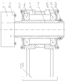
The utility model discloses a lathe cutting machining clamp. The lathe cutting machining clamp comprises a clamp seat (10), a shaft casing (5), a first bearing (4), a second bearing (6), a hollow rotary shaft (7), a flange plate (2) and a self-centering chuck (1), wherein the bottom of the clamp seat (10) is matched with a guide rail of a lathe body, the shaft casing (5) is fixedly connected with the clamp seat (10), outer circles of the first bearing (4) and the second bearing (6) are arranged at two end portions of the shaft casing (5) in a matched mode, the hollow rotary shaft (7) is arranged in the inner circles of the first bearing (4) and the second bearing (6) in a matched mode, the flange plate (2) is fixedly connected with one end of the hollow rotary shaft (7), the self-centering chuck (1) is connected with the flange plate (2) in a detachable mode, and after the clamp seat (10) is arranged on the guide rail of the lathe body in a matched mode, the self-centering chuck (1) has the same axis with the chunk of the lathe. When the lathe cutting machining clamp is used for carrying out cutting machining on a long and thin workpiece, two fixing points are provided. The long and thin workpiece is not prone to bending and deformation when affected by radial cutting. Besides, the lathe cutting machining clamp does not produce vibration easily, improves the machining accuracy, and solves the technical problem that the thin and long workpiece is not high in cutting machining accuracy in the prior art.
Description
Technical field
The present invention relates to a kind of frock clamp, especially relate to a kind of clamp for cutting for Cutting Process.
Background technology
At present, the processing to slender piece on the lathe is the hilted broadsword cutting, and slender piece is in working angles, it is subjected to radial cutting force to affect flexible distortion, and produces vibration easily, and machining accuracy is not high, operation easier is large, and is high to operator's technology and experience requirement, is difficult to improve the product quality of workpiece.
The utility model content
In order to overcome existing deficiency to the slender piece Machining Technology for Cutting.The utility model proposes a kind of clamp for cutting for Cutting Process, be intended to solve in the prior art to the not high technical problem of slender piece machining precision.
In order to solve the problems of the technologies described above, the technical scheme of the clamp for cutting that the utility model provides is as follows: a kind of lathe grinding clamp for machining has the clamping fixture seat that the bottom cooperates with guide ways on lathe bed; The pipe spreader that is fixedly connected with described clamping fixture seat; The outer ring cooperates clutch shaft bearing and the second bearing that is installed on described pipe spreader both ends; Cooperate the hollow rotating shaft that is installed in described clutch shaft bearing and the second bearing inner race; The ring flange that is fixedly connected with described hollow rotating shaft one end; With the self-centering chuck that described ring flange removably connects, after described clamping fixture seat cooperates on the guide rail that is installed in the body of lathe bed, the chuck concentric of described self-centering chuck and lathe.
Further, the lathe grinding clamp for machining also has the first end cap and the second end cap that is detachably connected on described pipe spreader two ends.
Further, the self-centering chuck of lathe grinding clamp for machining is three-jaw or four paws self-centering chuck.
Further, the lathe grinding clamp for machining also has the hold-down nut that stops hollow rotating shaft to slide in described clutch shaft bearing and the second bearing.
Above-mentioned improvement project can be implemented alone or in combination in the situation of not conflicting.
Self-centering chuck utilizes screw, and the screw by on the disk body seam end face is fastened on chuck on the flange, spanner is inserted in arbitrary gear square hole, and during rotating spanner, pinion drives parcel and rotates, by the rotation of parcel end-face helical, the drive claw becomes simultaneously into or disperses.But the claw radial concentric of self-centering chuck moves and makes the workpiece self-centering, and its structure belongs to known technology in the lathe technical field.
The utility model has following beneficial effect: during work, the lathe grinding clamp for machining is installed on the guide ways on lathe bed, after slender piece passes from the hollow rotating shaft of clamp for cutting, one end grips with the chuck of lathe, self-centering chuck with clamp for cutting grips again, can carry out machining to slender piece, because the chuck of lathe and the self-centering chuck of clamp for cutting are on the same axle center, add the man-hour slender piece and have two fixing points, when being affected by radial cutting force, it is difficult for flexural deformation, and be difficult for producing vibration, improved machining accuracy, thereby solved in the prior art the not high technical problem of slender piece machining precision.
Description of drawings
Accompanying drawing is used to provide further understanding of the present utility model, consists of the application's a part, and illustrative examples of the present utility model and explanation thereof are used for explaining the utility model, do not consist of improper restriction of the present utility model.In the accompanying drawings:
Fig. 1 is the structural representation of embodiment clamp for cutting;
Fig. 2 is that the embodiment clamp for cutting uses view.
The specific embodiment
Clamp for cutting has clamping fixture seat 10 as shown in Figure 1, the bottom of clamping fixture seat 10 is provided with groove, cooperate with V-way and the rectangular guideway of the body of lathe bed, accurate location when being convenient to install, pipe spreader 5 is fixedly connected with the top of described clamping fixture seat 10, the both ends of pipe spreader 5 have bearing block, the outer ring of clutch shaft bearing 4 and the second bearing 6 cooperates respectively in the bearing block that is installed in described pipe spreader 5 both ends, hollow rotating shaft 7 cooperations are installed in the inner ring of described clutch shaft bearing 4 and the second bearing 6, ring flange 2 is fixedly connected with the first end of described hollow rotating shaft 7, the first end cap 3 and the second end cap 9 removably are connected to the two ends of described pipe spreader 5 by bolt, three-jaw self-centering chuck 1 and described ring flange 2 removably are fixed together by bolt, after clamping fixture seat 10 cooperates on the V-way that is installed in the body of lathe bed and the rectangular guideway, the chuck concentric of described three-jaw self-centering chuck 1 and lathe.
In other embodiments, self-centering chuck can be four paws self-centering chuck etc.
In other embodiments, can not have the first end cap 3 and the second end cap 9.
In other embodiments, also have to be connected on the hollow rotating shaft 7 and stop hollow rotating shaft 7 at the hold-down nut 8 of described clutch shaft bearing 4 and the 6 interior slips of the second bearing.
As shown in Figure 2, during work, clamp for cutting is installed on lathe 11 bed ways, after slender piece 13 passes from the hollow rotating shaft 7 of clamp for cutting, one end grips with the chuck 12 of lathe 11, self-centering chuck 1 with clamp for cutting grips again, can carry out machining to slender piece 13, because the chuck 12 of lathe 11 self-centering chuck 1 with clamp for cutting is on the same axle center, add the man-hour slender piece and 13 have two fixing points, when being affected by radial cutting force, it is difficult for flexural deformation, and be difficult for producing vibration, improved machining accuracy, thereby solved in the prior art the not high technical problem of slender piece machining precision.
The above only is preferred embodiment of the present utility model, and limits never in any form the utility model, and for a person skilled in the art, the utility model can have various modifications and variations.All within spirit and principle that the utility model claims disclose, the modification of doing, be equal to replacement, improvement etc., all should be included within the protection domain of the present utility model.
Claims (4)
1. a lathe grinding clamp for machining is characterized in that: have the clamping fixture seat (10) that the bottom cooperates with guide ways on lathe bed; The pipe spreader (5) that is fixedly connected with described clamping fixture seat (10); The outer ring cooperates clutch shaft bearing (4) and the second bearing (6) that is installed on described pipe spreader (5) both ends; Cooperate the hollow rotating shaft (7) that is installed in described clutch shaft bearing (4) and the second bearing (6) inner ring; The ring flange (2) that is fixedly connected with described hollow rotating shaft (7) one ends; With the self-centering chuck (1) that described ring flange (2) removably connects, after described clamping fixture seat (10) cooperates on the guide rail that is installed in the body of lathe bed, the chuck concentric of described self-centering chuck (1) and lathe.
2. lathe grinding clamp for machining according to claim 1 is characterized in that: also have the first end cap (3) and the second end cap (9) that are detachably connected on described pipe spreader (5) two ends.
3. lathe grinding clamp for machining according to claim 1, it is characterized in that: self-centering chuck (1) is three-jaw or four paws self-centering chuck.
4. lathe grinding clamp for machining according to claim 1 is characterized in that: also have be connected to the upper hold-down nut (8) that stops hollow rotating shaft (7) to slide of hollow rotating shaft (7) in described clutch shaft bearing (4) and the second bearing (6).
Priority Applications (1)
| Application Number | Priority Date | Filing Date | Title |
|---|---|---|---|
| CN 201220563120 CN202877948U (en) | 2012-10-31 | 2012-10-31 | Lathe cutting machining clamp |
Applications Claiming Priority (1)
| Application Number | Priority Date | Filing Date | Title |
|---|---|---|---|
| CN 201220563120 CN202877948U (en) | 2012-10-31 | 2012-10-31 | Lathe cutting machining clamp |
Publications (1)
| Publication Number | Publication Date |
|---|---|
| CN202877948U true CN202877948U (en) | 2013-04-17 |
Family
ID=48069413
Family Applications (1)
| Application Number | Title | Priority Date | Filing Date |
|---|---|---|---|
| CN 201220563120 Expired - Fee Related CN202877948U (en) | 2012-10-31 | 2012-10-31 | Lathe cutting machining clamp |
Country Status (1)
| Country | Link |
|---|---|
| CN (1) | CN202877948U (en) |
Cited By (5)
| Publication number | Priority date | Publication date | Assignee | Title |
|---|---|---|---|---|
| CN104029035A (en) * | 2014-05-23 | 2014-09-10 | 含山县兴达球墨铸铁厂 | Tubular workpiece clamp for lathe |
| CN104070407A (en) * | 2014-06-26 | 2014-10-01 | 南京梅山冶金发展有限公司 | Device and method for processing vibration of drill rod |
| CN106270578A (en) * | 2016-10-20 | 2017-01-04 | 四川明日宇航工业有限责任公司 | Reversed turning device for the processing of spring steel slender rod piece |
| CN107612184A (en) * | 2017-10-19 | 2018-01-19 | 广州市瑞宝电器有限公司 | A kind of integrated motor end cap and its method for fine finishing |
| CN111790584A (en) * | 2019-04-08 | 2020-10-20 | 武汉中科锐择光电科技有限公司 | Ultraviolet curing device for curing optical fiber gyroscope ring |
-
2012
- 2012-10-31 CN CN 201220563120 patent/CN202877948U/en not_active Expired - Fee Related
Cited By (6)
| Publication number | Priority date | Publication date | Assignee | Title |
|---|---|---|---|---|
| CN104029035A (en) * | 2014-05-23 | 2014-09-10 | 含山县兴达球墨铸铁厂 | Tubular workpiece clamp for lathe |
| CN104070407A (en) * | 2014-06-26 | 2014-10-01 | 南京梅山冶金发展有限公司 | Device and method for processing vibration of drill rod |
| CN106270578A (en) * | 2016-10-20 | 2017-01-04 | 四川明日宇航工业有限责任公司 | Reversed turning device for the processing of spring steel slender rod piece |
| CN107612184A (en) * | 2017-10-19 | 2018-01-19 | 广州市瑞宝电器有限公司 | A kind of integrated motor end cap and its method for fine finishing |
| CN107612184B (en) * | 2017-10-19 | 2024-02-20 | 广州市瑞宝电器有限公司 | Integrated motor end cover and finish machining method thereof |
| CN111790584A (en) * | 2019-04-08 | 2020-10-20 | 武汉中科锐择光电科技有限公司 | Ultraviolet curing device for curing optical fiber gyroscope ring |
Similar Documents
| Publication | Publication Date | Title |
|---|---|---|
| CN202877948U (en) | Lathe cutting machining clamp | |
| CN203679749U (en) | Cutting machine with multiple functions of turning, grinding and cutting | |
| CN204234843U (en) | The continuous multiaspect milling device of a kind of CNC milling machine | |
| CN202655913U (en) | Rotary type workbench and vertical type turn milling compound machine tool | |
| CN202742034U (en) | Turn-milling machining equipment for wheel hub bearings | |
| CN205325468U (en) | Motor rotation number measuring device of numerically control grinder | |
| CN202824712U (en) | Index chuck device | |
| CN203779185U (en) | Automatic 90-degree transposition lathe turning clamp for electric tool head casing | |
| CN203141097U (en) | Tire segmental mould inclined plane boring-milling machine | |
| CN202317191U (en) | Milling machine for axial oil groove of lining | |
| CN106475872A (en) | Automotive drum type braking piece intrados milling drum | |
| CN202684099U (en) | Incircle pretreating device for cylinder sleeve | |
| CN204771766U (en) | Driver plate of two -way cutting railway freight car axletree of numerical control sleeping carriage | |
| CN204524268U (en) | High-speed numeric control lathe feeding drive mechanism | |
| CN203972893U (en) | A kind of hydraulic locking power cutter platform | |
| CN102975036A (en) | Building hoist stand column port cutting fixture and machining method of stand column port | |
| CN203944846U (en) | A kind of lathe multi-station attachment device | |
| CN203664735U (en) | Combined type multi-hole drilling machine | |
| CN201744901U (en) | Multistation machine tool | |
| CN202180210U (en) | Tailstock ejector device used for vertical lathe | |
| CN206305801U (en) | A kind of driving axle end tooth nosing fork boring earhole, car jump-ring slot fixture | |
| CN203293021U (en) | Grinding machine of grinding chuck wedge socket | |
| CN103878619B (en) | 90 ° of lathe jig for turning shafts of electric tool head capsule automatic position-changing | |
| CN205519673U (en) | Oval lathe of numerical control | |
| CN205614474U (en) | Vertical honing machine's main shaft feed mechanism |
Legal Events
| Date | Code | Title | Description |
|---|---|---|---|
| C14 | Grant of patent or utility model | ||
| GR01 | Patent grant | ||
| CF01 | Termination of patent right due to non-payment of annual fee |
Granted publication date: 20130417 Termination date: 20151031 |
|
| EXPY | Termination of patent right or utility model |