CN202872884U - Audio output circuit and mobile terminal - Google Patents
Audio output circuit and mobile terminal Download PDFInfo
- Publication number
- CN202872884U CN202872884U CN 201220502176 CN201220502176U CN202872884U CN 202872884 U CN202872884 U CN 202872884U CN 201220502176 CN201220502176 CN 201220502176 CN 201220502176 U CN201220502176 U CN 201220502176U CN 202872884 U CN202872884 U CN 202872884U
- Authority
- CN
- China
- Prior art keywords
- power amplifier
- signal
- audio output
- circuit
- analog switch
- Prior art date
- Legal status (The legal status is an assumption and is not a legal conclusion. Google has not performed a legal analysis and makes no representation as to the accuracy of the status listed.)
- Expired - Lifetime
Links
Images

Abstract
The utility model discloses an audio output circuit and a mobile terminal. The audio output circuit comprises a loudspeaker, an analog change-over switch, a filter circuit and a power amplifier; a loudspeaker signal outputted by a processor passes through the filter circuit and the power amplifier and then is outputted to one group of switch channels of the analog change-over switch; and another group of switch channels of the analog change-over switch receives a receiver signal outputted by the processor. And a control terminal of the analog change-over switch receives a channel selection signal outputted by the processor to select one group of switch channels to be communicated with a common terminal of the analog change-over switch. Besides, the common terminal of the analog change-over switch is connected with the loudspeaker. According to the audio output circuit provided by the utility model, the receiver and the loudspeaker are integrated into one; one loudspeaker is employed to cooperate with a simple peripheral circuit, so that two output modes of the audio signal can be realized, wherein the two output modes include a receiver output mode and a loudspeaker output mode. Therefore, the receiver is saved; the circuit cost is reduced; the PCB space is saved; and the structural design is optimized.
Description
Technical field
The utility model belongs to the voicefrequency circuit technical field, specifically, relate to a kind of receiver and loud speaker be united two into one the portable terminal of realizing the audio output circuit design of two kinds of play mode and adopting described audio output circuit design by an electro-acoustic element.
Background technology
At present, the path that mobile phone plays sound has two: one is to send from receiver, and when adopting hand-held mode to receive calls, this pattern using situation is maximum.When hand-held conversation, because people's ear is relatively pressed close to receiver, the sound that therefore requires to answer need not be too large, but must sound clear, clean, continuous.Other one is to send from loud speaker, and as adopting the hands free mode answering phone or utilizing loud speaker to play MP3 music etc., this moment, people's ear was far away apart from loud speaker, requires sound enough large in distortionless situation, but can slight reduction to the requirement of low noise.
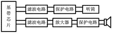
In the circuit design of present mobile phone products, the design of two audio frequency output channels comprises the chief components such as filter circuit, protective circuit, external audio frequency amplifier, electro-acoustic transducing device referring to circuit structure shown in Figure 1.Its operation principle is: after the baseband chip of audio signal process interior of mobile phone carries out the processing such as encoding and decoding, digital-to-analogue conversion, power amplification; export filter circuit to and filter out wherein DC component and the ripple signal of making an uproar such as High-frequency Interference; and then preventing static damage by protective circuit, the voice signal that by electro-acoustic transducing devices such as receiver or loud speakers analog electrical signal conversion adult ear can be identified at last plays back.Usually, the receiver path utilizes the amplifying circuit of baseband chip inside can produce enough large signal and drives the receiver broadcast; But if audio signal need to be sent from loud speaker, then the amplifying circuit of baseband chip inside is not enough to directly drive loud speaker, needs to increase the driving force that external audio-frequency power amplifier improves audio signal.
In order to satisfy two kinds of audio signal output requirements, existing circuit design mode all is independently audio frequency output channels of two of designs, and namely receiver path and loud speaker path are processed respectively output to audio signal, i.e. as shown in Figure 1 circuit structure.Adopt this audio output circuit design, not only hardware cost is high, and need to take larger PCB space, so that the space of interior of mobile phone becomes at full stretch, is not suitable for being applied in ultra-thin, the small and exquisite smart mobile phone product.
In addition, existing most of mobile phone all is that receiver is designed in the front of mobile phone, and loud speaker is laid in the back side of mobile phone.Usually be placed on bed etc. above the soft thing time when mobile phone faces up, greatly reduce because soft thing blocks the ringing tone that will send a telegram here, even can't hear incoming ring tone, cause the user to miss phone or can't hear alarm clock sound etc., affected user's normal use.
Summary of the invention
The purpose of this utility model is to provide a kind of audio output circuit, adopt a loud speaker can realize two kinds of output modes of audio signal, be receiver output mode and loud speaker output mode, not only saved an electro-acoustic transducing device, simplified circuit structure, and reduced the space hold of PCB, optimized space structure.
For solving the problems of the technologies described above, the utility model is achieved by the following technical solutions:
A kind of audio output circuit, comprise loud speaker, analog switch, filter circuit and a power amplifier, export wherein one group of switch passage of analog switch to via filter circuit and power amplifier by the loudspeaker signal of processor output, the receiver signal of other one group of switch passage receiving processor output of analog switch, the channel selecting signal of the control end receiving processor output of analog switch, selection wherein one group of switch passage is communicated with the common port of analog switch, and the common port of described analog switch connects loud speaker.
In order to satisfy the requirement of impedance matching, the receiver signal of described processor output transfers to one group of switch passage of analog switch via impedance matching circuit.
Further, described processor is exported described receiver signal by one group difference signal terminal, described difference signal terminal all is in series with one tunnel build-out resistor on each the bar differential signal line that is connected with analog switch, to reach the effect with the impedance phase of loud speaker coupling.
Preferably, because the input band of loud speaker is limited, therefore select high-pass filtering circuit as described filter circuit, its cut-off frequency preferably is arranged on 362Hz.
Further, the loudspeaker signal of described processor output difference form-separating, transfer to respectively the difference audio input end of power amplifier, after carrying out power amplification and process by power amplifier, export analog switch to via the difference audio output of power amplifier; The negative polarity difference audio output of described power amplifier is by the negative polarity difference audio input end of feedback resistance connection power amplifier, and the bypass voltage end of described power amplifier connects the positive polarity difference audio input end of power amplifier by another feedback resistance.
Further again, the enable signal of the switch control end receiving processor output of described power amplifier, described switch control end is preferably by pull down resistor ground connection, with the stabilization signal level.
Preferably, described power amplifier preferably adopts the audio-frequency power amplifier of AB class, to prevent producing plosive and clocking noise when power amplifier opens and closes.
Further, on the common port of described analog switch and circuit that loud speaker is connected, also be connected with π type capacitor filter and electrostatic discharge protective circuit, with the filtering High-frequency Interference, and play the effect that prevents electrostatic damage.
Based on above-mentioned audio output circuit structure, the utility model also provides a kind of portable terminal that adopts described audio output circuit design, comprise processor, a loud speaker, analog switch, filter circuit and power amplifier, export wherein one group of switch passage of analog switch to via filter circuit and power amplifier by the loudspeaker signal of processor output, the receiver signal of other one group of switch passage receiving processor output of analog switch, the channel selecting signal of the control end receiving processor output of analog switch, selection wherein one group of switch passage is communicated with the common port of analog switch, and the common port of described analog switch connects loud speaker.
Preferably, described loud speaker preferred cloth is located on the front housing of portable terminal, and when avoiding being placed on portable terminal on the soft object plane, the sound that causes owing to blocking of soft object plane playing back by loud speaker is significantly cut down.
Compared with prior art, advantage of the present utility model and good effect are: audio output circuit of the present utility model unites two into one receiver and loud speaker, adopt a loud speaker to cooperate simple peripheral circuit can realize two kinds of output modes of audio signal, be receiver output mode and loud speaker output mode, not only saved receiver, reduced circuit cost, saved the PCB space, optimized structural design, and by this loud speaker being placed on the front of mobile phone, can so that the ring back tone or the alarm clock sound that play back by loud speaker can not cut down because blocking, guarantee user's normal use.In addition, adopt audio output circuit design of the present utility model when playing sound by receiver, make an uproar at the bottom of can reducing receiver, the user is provided preferably call tone quality.
After reading by reference to the accompanying drawings the detailed description of the utility model execution mode, other characteristics of the present utility model and advantage will become clearer.
Description of drawings
Fig. 1 is the theory diagram of the dual-channel audio output circuit that adopts of existing mobile phone;
Fig. 2 is the schematic block circuit diagram of a kind of embodiment of the audio output circuit that proposes of the utility model;
Fig. 3 is the physical circuit schematic diagram of a kind of embodiment of audio output circuit shown in Figure 2.
Embodiment
Below in conjunction with accompanying drawing embodiment of the present utility model is described in detail.
The utility model is in order to simplify the structural design of voice-frequency channel, to adapt to the lightening appearance design requirements of portable terminal product such as mobile phone, the method for designing that employing unites two into one receiver and loud speaker, the use of cancellation receiver component, only can realize the selection switching of receiver and two kinds of audio-frequency play modes of loud speaker by lay a loud speaker at the portable terminal product, not only on circuit structure and hardware cost, greatly optimize, simultaneously also greatly convenient for users to use.
The below elaborates concrete assembling structure and the operation principle thereof of described audio output circuit take mobile phone products as example by a specific embodiment.
Embodiment one, and the audio output circuit of present embodiment is mainly by filter circuit, power amplifier, analog switch with an electro-acoustic transducing device---loud speaker forms, referring to shown in Figure 2.Wherein, analog switch is used for the two-way audio signal (being receiver signal and loudspeaker signal) of output after the encoding and decoding of processor process, digital-to-analogue conversion and the power amplification processing is switched output.Processed owing in processor, having overdrived to amplify by the receiver signal of processor output, therefore can directly transfer to wherein one group of switch passage of analog switch, when the user selection hand-held mode receives calls, export loud speaker to by the analog switch gating, as the faint audio signal of receiver output, this moment, the user need to press close to ear the voice signal that loud speaker is answered the other side with loud speaker.For the loudspeaker signal of processor output, owing to need larger driving force, therefore need to increase one-level drive amplification circuit and satisfy driving requirement to loud speaker.Given this, present embodiment will at first carry out filtering by filter circuit by the loudspeaker signal of processor output to be processed, then transfer to power amplifier and carry out the drive amplification processing, export at last other one group of switch passage of analog switch to, when user selection hands free mode answering phone or music playing, export loud speaker to by the analog switch gating, play output audio signal.
For the gating control of analog switch, by the channel selecting signal control realization of processor output.Specifically, can be with the control end IN1 of analog switch S1, IN2 is connected on wherein one road GPIO mouth of processor, the channel selecting signal AUDIO_SWITCH_CTL of receiving processor output, and then according to the high-low level state of described channel selecting signal AUDIO_SWITCH_CTL, select wherein one group of switch passage NC1 of analog switch S1, NC2(or NO1, NO2) with its common port COM1, COM2 is communicated with, and then with the receiver signal or via the common port COM1 of the loudspeaker signal of exporting after the power amplifier amplification processing by analog switch S1, COM2 transfers to loud speaker, drive the loud speaker output audio signal, in conjunction with shown in Figure 3.
In order to reach the designing requirement of impedance matching, between the receiver signal output part of processor and described analog switch, need to set up impedance matching circuit, with satisfy and the rear class loud speaker between the impedance matching requirement.
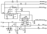
As a kind of preferred design of present embodiment, preferably adopt the baseband chip that is integrated with CPU in the mobile phone as described processor, output two-way audio signal.The two-way audio signal that produces take baseband chip is specifically described as the differential signal form as example, referring to shown in Figure 3.Among Fig. 3, REC+ and REC-are the receiver signals of the difference form of baseband chip output, by one group of difference signal terminal output of baseband chip.This road signal is inner through after amplifying processing at baseband chip, can directly drive 32 ohm receiver output.But, in the present embodiment, in order to connect the loud speaker output that drives 8 ohm, need to be on the switch passage NO1 of analog switch S1, each bar differential signal line that NO2 connects described difference signal terminal series matching resistor, for example 12 ohm resistance R 7 and R8 are to reach the effect of impedance matching.
The loudspeaker signal SPEAKER+ and the SPEAKER-that are produced by baseband chip also are differential signal, because the input band of rear end loud speaker is limited, therefore needs to increase the high-pass filtering circuit low frequency signal that some are unnecessary and filter out.In the circuit design of present embodiment, the mode that adopts resistance and electric capacity to be in series designs described high-pass filtering circuit, as shown in Figure 3, comprises two series arms, and correspondence is connected on two differential signal lines respectively.Wherein, article one series arm of forming of resistance R 1 and capacitor C 1 is connected between negative polarity difference audio input end-IN of the terminal of baseband chip output negative pole loudspeaker signal SPEAKER-and power amplifier IC1; The second series arm that resistance R 2 and capacitor C 2 forms is connected between positive polarity difference audio input end+IN of the terminal of baseband chip output cathode loudspeaker signal SPEAKER+ and power amplifier IC1.The high-pass filtering circuit that adopts the RC series connection to form, capacitor C 1, C2 play every straight effect, form high pass filter with resistance R 1, the R2 of back, and the parameter value by selection RC arranges its cut-off frequency F
C=362Hz.So, the loudspeaker signal SPEAKER+ by baseband chip output and SPEAKER-are after carrying out filtering and processing via high pass filter, and the low frequency signal that just its medium frequency can be lower than 362Hz filters out, to satisfy the input requirements of rear class loud speaker.
In the present embodiment, described power amplifier IC1 preferably adopts the power amplifier of AB class, and have<1% THD+N(THD+N is the abbreviation of English Total Hormonic Distortion+Noise, it is the total harmonic distortion plus noise, it is a main performance index of audio-frequency power amplifier, also be a condition of the rated output power of audio-frequency power amplifier) low-noise performance, when opening and closing, can effectively prevent POP sound and CLICK noise, be plosive and clocking noise, allow people's ear obtain maximum comfort.
The negative polarity difference audio output Vo1 of described power amplifier IC1 is connected to negative polarity difference audio input end-IN of power amplifier IC1 by feedback resistance R4, and the bypass voltage end BYPASS of power amplifier IC1 is connected to positive polarity difference audio input end+IN of power amplifier IC1 by feedback resistance R3.Select the resistance of feedback resistance R3, R4 to be 56K Ω, the multiplication factor of power amplifier IC1 can be arranged on 1+R4/R1=1+56K/20K=3.8 thus, drive rated power as the loud speaker of 0.8W to reach.
In order to reach energy-saving and cost-reducing purpose of design, control described power amplifier IC1 and only when the needs output audio signal, start operation.In order to realize this purpose of design, present embodiment connects baseband chip with the switch control end SHUTDOWN of described power amplifier IC1, receives the enable signal SPK_PA_EN of baseband chip output.For the stabilization signal level, increase pull down resistor R5, be about to the switch control end SHUTDOWN of described power amplifier IC1 by resistance R 5 ground connection.When the enable signal SPK_PA_EN of baseband chip output was high level, power amplifier IC1 was in the power amplification pattern, and when enable signal SPK_PA_EN was low level, power amplifier IC1 was in " shut " mode", and power consumption can be lower than 0.1uA.
In order to eliminate or to reduce power supply VBATT to the impact of audio signal, with the magnetic bead L1 connection power supply VBATT of energization pins VDD by connecting of power amplifier IC1, and via filter capacitor C4 ground connection.The loudspeaker signal that process power amplifier IC1 amplifies transfers to other a group of switch passage NC1, the NC2 of analog switch S1 by difference audio output Vo1 and the Vo2 output of power amplifier IC1.
The channel selecting signal AUDIO_SWITCH_CTL that analog switch S1 is exported by baseband chip controls and chooses loud speaker path or receiver path.When channel selecting signal AUDIO_SWITCH_CTL was high level, analog switch S1 switched to the receiver path, and output receiver signal REC+, REC-are used for hand-held mode this moment to loud speaker.When channel selecting signal AUDIO_SWITCH_CTL was low level, analog switch S1 switched to the loud speaker path, and the loudspeaker signal after output is processed via power amplifier IC1 amplification is used for hands-free or ring isotype this moment.
In order to improve described audio output circuit Operation safety; present embodiment also is designed with protective circuit between difference audio input interface SP+, the SP-of common port COM1, the COM2 of analog switch S1 and loud speaker; referring to Fig. 2, shown in Figure 3, comprise π type capacitor filter and electrostatic discharge protective circuit two parts.Wherein, π type capacitor filter is formed by connecting by three capacitor C 6, C7, C8, and capacitor C 6, C7 play the effect that prevents that high-frequency signal from disturbing audio signal, and capacitor C 8 is in order to eliminate common mode disturbances.Electrostatic discharge protective circuit is managed (being Transient Suppression Diode) D1 by two TVS and is formed, and correspondence is connected between difference audio input interface SP+, the SP-and ground of loud speaker.When the loud speaker end is sensed instantaneous pressure static, TVS pipe D1 can moment with the electrostatic leakage of 10KV to ground, thereby play the especially effect of baseband chip of protection late-class circuit.When the both end voltage of TVS pipe D1 was relatively hanged down, it was equivalent to electric capacity, does not affect the normal transmission of audio signal.
For described loud speaker, can improve by the EQ parameter of curve of suitable adjustment baseband chip the amplitude of low frequency small-signal, and by adjusting the end parameter of making an uproar, make loud speaker under hand-held mode, keep the output of making an uproar of the low end, with raising audio frequency output quality.
The audio output circuit of present embodiment at first allows receiver signal and loudspeaker signal walk respectively separately path, then comes switched path by analog switch, has so both guaranteed that the low end of receiver makes an uproar, and has also guaranteed the louder volume under the speaker mode.Simultaneously, reduce hardware cost, optimized structural design.
In addition, for the installation position of described loud speaker on handset shell, the present embodiment preferred cloth is located on the front housing of mobile phone, can so that ring back tone sends from the front of mobile phone, prevent the little problem of the ringing tones such as incoming call that is blocked and brings because of loud speaker thus.
Certainly, the audio output circuit design that present embodiment proposes is equally applicable in other portable terminal products except mobile phone, and present embodiment does not specifically limit this.
Should be noted that; the above only is a kind of preferred implementation of the present utility model; for those skilled in the art; under the prerequisite that does not break away from the utility model principle; can also make some improvements and modifications, these improvements and modifications also should be considered as protection range of the present utility model.
Claims (10)
1. audio output circuit, it is characterized in that: comprise a loud speaker, analog switch, filter circuit and power amplifier, export wherein one group of switch passage of analog switch to via filter circuit and power amplifier by the loudspeaker signal of processor output, the receiver signal of other one group of switch passage receiving processor output of analog switch, the channel selecting signal of the control end receiving processor output of analog switch, selection wherein one group of switch passage is communicated with the common port of analog switch, and the common port of described analog switch connects loud speaker.
2. audio output circuit according to claim 1 is characterized in that: the receiver signal of described processor output transfers to one group of switch passage of analog switch via impedance matching circuit.
3. audio output circuit according to claim 2, it is characterized in that: described processor is exported described receiver signal by one group difference signal terminal, and described difference signal terminal all is in series with one tunnel build-out resistor on each the bar differential signal line that is connected with analog switch.
4. audio output circuit according to claim 1, it is characterized in that: described filter circuit is high-pass filtering circuit, its cut-off frequency is 362Hz.
5. audio output circuit according to claim 1, it is characterized in that: the loudspeaker signal of described processor output difference form-separating, transfer to respectively the difference audio input end of power amplifier, after carrying out power amplification and process by power amplifier, export analog switch to via the difference audio output of power amplifier; The negative polarity difference audio output of described power amplifier is by the negative polarity difference audio input end of feedback resistance connection power amplifier, and the bypass voltage end of described power amplifier connects the positive polarity difference audio input end of power amplifier by another feedback resistance.
6. audio output circuit according to claim 5 is characterized in that: the enable signal of the switch control end receiving processor output of described power amplifier, described switch control end is by pull down resistor ground connection.
7. audio output circuit according to claim 5, it is characterized in that: described power amplifier is the audio-frequency power amplifier of AB class.
8. each described audio output circuit in 7 according to claim 1 is characterized in that: the circuit that is connected with loud speaker at the common port of described analog switch is connected with π type capacitor filter and electrostatic discharge protective circuit.
9. a portable terminal comprises processor, it is characterized in that: also comprise such as the described audio output circuit of each claim in the claim 1 to 8.
10. portable terminal according to claim 9, it is characterized in that: described loud speaker is laid on the front housing of portable terminal.
Priority Applications (1)
| Application Number | Priority Date | Filing Date | Title |
|---|---|---|---|
| CN 201220502176 CN202872884U (en) | 2012-09-28 | 2012-09-28 | Audio output circuit and mobile terminal |
Applications Claiming Priority (1)
| Application Number | Priority Date | Filing Date | Title |
|---|---|---|---|
| CN 201220502176 CN202872884U (en) | 2012-09-28 | 2012-09-28 | Audio output circuit and mobile terminal |
Publications (1)
| Publication Number | Publication Date |
|---|---|
| CN202872884U true CN202872884U (en) | 2013-04-10 |
Family
ID=48039567
Family Applications (1)
| Application Number | Title | Priority Date | Filing Date |
|---|---|---|---|
| CN 201220502176 Expired - Lifetime CN202872884U (en) | 2012-09-28 | 2012-09-28 | Audio output circuit and mobile terminal |
Country Status (1)
| Country | Link |
|---|---|
| CN (1) | CN202872884U (en) |
Cited By (9)
| Publication number | Priority date | Publication date | Assignee | Title |
|---|---|---|---|---|
| CN104581515A (en) * | 2013-10-15 | 2015-04-29 | 联想(北京)有限公司 | Audio playing device and method as well as mobile terminal |
| CN106714031A (en) * | 2015-08-10 | 2017-05-24 | 上海芯望电子技术有限公司 | Integrated audio signal player |
| CN108012220A (en) * | 2017-12-29 | 2018-05-08 | 上海艾为电子技术股份有限公司 | Audio processor |
| CN108206977A (en) * | 2018-01-11 | 2018-06-26 | 上海展扬通信技术有限公司 | Noise-reduction method, device and the computer readable storage medium of audio |
| CN108351694A (en) * | 2015-11-04 | 2018-07-31 | 三星电子株式会社 | Electronic equipment and its operating method |
| CN110071694A (en) * | 2018-01-22 | 2019-07-30 | 深圳市澳德新能源科技有限公司 | Audio power amplifier circuit |
| CN110399115A (en) * | 2019-08-14 | 2019-11-01 | 北京计算机技术及应用研究所 | A kind of anti-interference dual-channel audio voice switching device |
| CN113014706A (en) * | 2021-03-04 | 2021-06-22 | 瑞声光电科技(常州)有限公司 | Loudspeaker driving method and circuit for mobile equipment |
| CN114257702A (en) * | 2021-11-04 | 2022-03-29 | 科大讯飞股份有限公司 | Audio and video processing circuit, control method, control device and electronic equipment |
-
2012
- 2012-09-28 CN CN 201220502176 patent/CN202872884U/en not_active Expired - Lifetime
Cited By (12)
| Publication number | Priority date | Publication date | Assignee | Title |
|---|---|---|---|---|
| CN104581515A (en) * | 2013-10-15 | 2015-04-29 | 联想(北京)有限公司 | Audio playing device and method as well as mobile terminal |
| CN104581515B (en) * | 2013-10-15 | 2018-12-18 | 联想(北京)有限公司 | A kind of audio playing apparatus, method and mobile terminal |
| CN106714031A (en) * | 2015-08-10 | 2017-05-24 | 上海芯望电子技术有限公司 | Integrated audio signal player |
| CN108351694A (en) * | 2015-11-04 | 2018-07-31 | 三星电子株式会社 | Electronic equipment and its operating method |
| CN108012220A (en) * | 2017-12-29 | 2018-05-08 | 上海艾为电子技术股份有限公司 | Audio processor |
| CN108206977A (en) * | 2018-01-11 | 2018-06-26 | 上海展扬通信技术有限公司 | Noise-reduction method, device and the computer readable storage medium of audio |
| CN110071694A (en) * | 2018-01-22 | 2019-07-30 | 深圳市澳德新能源科技有限公司 | Audio power amplifier circuit |
| CN110399115A (en) * | 2019-08-14 | 2019-11-01 | 北京计算机技术及应用研究所 | A kind of anti-interference dual-channel audio voice switching device |
| CN110399115B (en) * | 2019-08-14 | 2023-09-26 | 北京计算机技术及应用研究所 | Anti-interference double-channel audio frequency voice switching device |
| CN113014706A (en) * | 2021-03-04 | 2021-06-22 | 瑞声光电科技(常州)有限公司 | Loudspeaker driving method and circuit for mobile equipment |
| CN114257702A (en) * | 2021-11-04 | 2022-03-29 | 科大讯飞股份有限公司 | Audio and video processing circuit, control method, control device and electronic equipment |
| CN114257702B (en) * | 2021-11-04 | 2024-02-13 | 科大讯飞股份有限公司 | Audio and video processing circuit, control method, control device and electronic equipment |
Similar Documents
| Publication | Publication Date | Title |
|---|---|---|
| CN202872884U (en) | Audio output circuit and mobile terminal | |
| CN104935742B (en) | Communication terminal and the method for improving its tonequality under handset mode | |
| CN104717588A (en) | Low-power-consumption in-ear type active noise reduction earphone and noise reduction method | |
| CN204578728U (en) | A kind of active noise reduction earphone | |
| CN104754436A (en) | Active noise reducing method and noise reducing earphone | |
| JPH0621730A (en) | Weak power amplifier/transducer driver by means of signal expansion | |
| CN202587132U (en) | Voice call circuit with echo suppression function and flat panel computer | |
| US20170111736A1 (en) | Audio bass compensation system and compensation method | |
| CN106303761A (en) | A kind of window talkback system and intercommunication method | |
| CN108012220A (en) | Audio processor | |
| CN201383326Y (en) | Noise reduction device of mobile phone | |
| CN202261181U (en) | Terminal using two-in-one loudspeaker | |
| CN106373586A (en) | Noise filtering circuit | |
| CN2817244Y (en) | Mobile phone sharing sigle circuit for talking and ringing | |
| CN205195931U (en) | Headset | |
| CN202111666U (en) | Voice circuit with high-frequency filter function and mobile terminal | |
| CN203151729U (en) | Multifunctional earphone | |
| CN203563181U (en) | Mobile terminal having KTS sound effect | |
| CN102340565A (en) | De-noising assembly | |
| CN204948330U (en) | Speaker circuit and mobile terminal | |
| CN106792359B (en) | Electronic equipment and audio power amplifier system thereof | |
| CN2772163Y (en) | Ear microphone | |
| CN211240070U (en) | Audio power amplifier switching circuit | |
| CN212992566U (en) | Hand microphone device of anti-interference USB interface | |
| CN211047195U (en) | Sound effect switching circuit, equipment and system |
Legal Events
| Date | Code | Title | Description |
|---|---|---|---|
| C14 | Grant of patent or utility model | ||
| GR01 | Patent grant | ||
| CX01 | Expiry of patent term |
Granted publication date: 20130410 |
|
| CX01 | Expiry of patent term |