CN202867291U - Headshaking fan with adjustable headshaking angle - Google Patents
Headshaking fan with adjustable headshaking angle Download PDFInfo
- Publication number
- CN202867291U CN202867291U CN 201220502646 CN201220502646U CN202867291U CN 202867291 U CN202867291 U CN 202867291U CN 201220502646 CN201220502646 CN 201220502646 CN 201220502646 U CN201220502646 U CN 201220502646U CN 202867291 U CN202867291 U CN 202867291U
- Authority
- CN
- China
- Prior art keywords
- headshaking
- fan
- angle
- adjustable
- connecting rod
- Prior art date
- Legal status (The legal status is an assumption and is not a legal conclusion. Google has not performed a legal analysis and makes no representation as to the accuracy of the status listed.)
- Expired - Fee Related
Links
Images


Abstract
Provided is a headshaking fan with an adjustable headshaking angle. The headshaking fan with the adjustable headshaking angle comprises a headshaking fan body and a headshaking mechanism. The headshaking mechanism comprises a headshaking motor output shaft, a variable quantity crank and a connecting rod. One end of the connecting rod is connected with a base of the headshaking fan body in a rotating mode through a bolt. The other end of the connecting rod is fixedly installed in a circular groove on the variable quantity crank though an angle adjusting knob, and the variable quantity crank is fixedly connected with the headshaking motor output shaft. The headshaking angle of the headshaking with the adjustable headshaking angle can be arbitrarily adjusted from 0 to 180 degrees. The headshaking fan with the adjustable headshaking angle is not only simple in structure, but also convenient to adjust. The headshaking fan with the adjustable headshaking angle is enabled to shake head in a needed angle range only by unscrewing the angle adjusting knob, adjusting the position of the angle adjusting knob in the circular groove, and screwing the angle adjusting knob.
Description
Technical field
The utility model relates to a kind of electric fan, is specially a kind of panning angle adjustable oscillating fan.
Background technique
Flooring fan of the prior art, bracker fan or the panning angle that is installed in the fan on the wall are changeless, although played in actual applications the effect of radiating and cooling, but sometimes cool breeze can not blow within doors everyone, and also sometimes wind is to no one's place, the waste resource; For example when the people of enjoyment cool breeze before electric fan relatively disperses, namely the required panning angle of electric fan is larger; And when the people who enjoys cool breeze sat more concentratedly, namely the required angle of shaking the head of electric fan was smaller.This demand, traditional electric oscillatory fans can't satisfy, so need the changeable electric fan of a kind of panning angle to satisfy the demand of people's daily life.
The model utility content
The technical problem that the utility model solves is to provide a kind of panning angle adjustable oscillating fan, to solve the problem that proposes in the above-mentioned background technology.
The technical problem that the utility model solves realizes by the following technical solutions:
Panning angle adjustable oscillating fan comprises head-shaking fan body and oscillating mechanism, and described oscillating mechanism comprises head-shaking motor output shaft, variable crank and connecting rod; One end of described connecting rod is rotationally connected by the base of bolt and head-shaking fan body, and the other end is fixedly mounted in the circular groove on the variable crank by the angle adjustment knob, and the variable crank is fixedly connected with the head-shaking motor output shaft.
The variable crank is changed into the variable bar, offer rectangle groove on the described variable bar.
Compared with prior art, the beneficial effects of the utility model are: panning angle of the present utility model can be regulated arbitrarily between 0~180 degree, not only simple in structure, and easy to adjust, only need unscrew the angle adjustment knob, regulate it in the position in circular groove, tighten again the angle adjustment knob fan is shaken the head in the angular range of needs.
Description of drawings
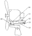
Fig. 1 is structural representation of the present utility model.
Fig. 2 is the structural representation of oscillating mechanism of the present utility model.
Fig. 3 is the structural representation of variable crank of the present utility model.
Fig. 4 is the structural representation of variable bar of the present utility model.
Embodiment
In order to make realization technological means of the present utility model, creation characteristic, to reach purpose and effect is easy to understand, below in conjunction with concrete diagram, further set forth the utility model.
Shown in Fig. 1~3, panning angle adjustable oscillating fan comprises head-shaking fan body and oscillating mechanism 1, and described oscillating mechanism 1 comprises head-shaking motor output shaft 11, variable crank 12 and connecting rod 13; One end of described connecting rod 13 is rotationally connected by bolt 16 base with the head-shaking fan body, and the other end is fixedly mounted in the circular groove 17 on the variable crank 12 by angle adjustment knob 15, and variable crank 12 is fixedly connected with head-shaking motor output shaft 11.
When fan work, 11 rotations of head-shaking motor output shaft, drive 12 rotations of variable crank, because the axis of angle adjustment knob 15 and head-shaking motor output shaft 11 is not on same straight line, and connecting rod 13 is connected with base, so force fan to swing around the back shaft 14 of head-shaking fan body, i.e. fan head swinging.
Panning angle of the present utility model can be regulated arbitrarily between 0~180 degree, not only simple in structure, and easy to adjust, only need unscrew angle adjustment knob 15, regulate it in the position in circular groove 17, tighten again angle adjustment knob 15 fan is shaken the head in the angular range of needs.
Embodiment 2
Make the variable crank 12 among the embodiment 1 into adjusting that variable bar 18 can be finished panning angle equally, offer rectangle groove 19 on the described variable bar 18.
More than show and described basic principle of the present utility model and major character and advantage of the present utility model.The technician of the industry should understand; the utility model is not restricted to the described embodiments; that describes in above-described embodiment and the specification just illustrates principle of the present utility model; under the prerequisite that does not break away from the utility model spirit and scope; the utility model also has various changes and modifications, and these changes and improvements all fall in claimed the utility model scope.Claimed scope of the present utility model is defined by appending claims and equivalent thereof.
Claims (2)
1. panning angle adjustable oscillating fan comprises head-shaking fan body and oscillating mechanism, and it is characterized in that: described oscillating mechanism comprises head-shaking motor output shaft, variable crank and connecting rod; One end of described connecting rod is rotationally connected by the base of bolt and head-shaking fan body, and the other end is fixedly mounted in the circular groove on the variable crank by the angle adjustment knob, and the variable crank is fixedly connected with the head-shaking motor output shaft.
2. panning angle adjustable oscillating fan according to claim 1 is characterized in that: the variable crank is changed into the variable bar, offer rectangle groove on the described variable bar.
Priority Applications (1)
| Application Number | Priority Date | Filing Date | Title |
|---|---|---|---|
| CN 201220502646 CN202867291U (en) | 2012-09-27 | 2012-09-27 | Headshaking fan with adjustable headshaking angle |
Applications Claiming Priority (1)
| Application Number | Priority Date | Filing Date | Title |
|---|---|---|---|
| CN 201220502646 CN202867291U (en) | 2012-09-27 | 2012-09-27 | Headshaking fan with adjustable headshaking angle |
Publications (1)
| Publication Number | Publication Date |
|---|---|
| CN202867291U true CN202867291U (en) | 2013-04-10 |
Family
ID=48034014
Family Applications (1)
| Application Number | Title | Priority Date | Filing Date |
|---|---|---|---|
| CN 201220502646 Expired - Fee Related CN202867291U (en) | 2012-09-27 | 2012-09-27 | Headshaking fan with adjustable headshaking angle |
Country Status (1)
| Country | Link |
|---|---|
| CN (1) | CN202867291U (en) |
Cited By (3)
| Publication number | Priority date | Publication date | Assignee | Title |
|---|---|---|---|---|
| CN107542694A (en) * | 2017-07-28 | 2018-01-05 | 广东美的环境电器制造有限公司 | Fan method for controlling rotation, system and fan |
| CN108869408A (en) * | 2018-06-29 | 2018-11-23 | 池州市佳山信息技术有限公司 | A kind of apparent electric fan of muting function |
| CN109058142A (en) * | 2018-09-25 | 2018-12-21 | 江苏科创电器有限公司 | A kind of adjustable fan head-shaking device of panning angle and fan |
-
2012
- 2012-09-27 CN CN 201220502646 patent/CN202867291U/en not_active Expired - Fee Related
Cited By (4)
| Publication number | Priority date | Publication date | Assignee | Title |
|---|---|---|---|---|
| CN107542694A (en) * | 2017-07-28 | 2018-01-05 | 广东美的环境电器制造有限公司 | Fan method for controlling rotation, system and fan |
| CN107542694B (en) * | 2017-07-28 | 2019-09-03 | 广东美的环境电器制造有限公司 | Fan method for controlling rotation, system and fan |
| CN108869408A (en) * | 2018-06-29 | 2018-11-23 | 池州市佳山信息技术有限公司 | A kind of apparent electric fan of muting function |
| CN109058142A (en) * | 2018-09-25 | 2018-12-21 | 江苏科创电器有限公司 | A kind of adjustable fan head-shaking device of panning angle and fan |
Similar Documents
| Publication | Publication Date | Title |
|---|---|---|
| CN202867291U (en) | Headshaking fan with adjustable headshaking angle | |
| CN204841529U (en) | Reciprocating type oscillator | |
| WO2008043165A3 (en) | Power generating device | |
| CN206360913U (en) | Horizontal hunting adjustable fan | |
| CN202082819U (en) | Lamp irradiation direction regulating structure | |
| CN206529695U (en) | Board-like vibration damping suspension rod | |
| CN207989370U (en) | The electric fan of oscillating angle adjusting | |
| CN106758816B (en) | Board-like vibration damping sunpender | |
| CN204005811U (en) | A kind of car light luminescence unit fascinates up and down to regulate and uses open slot rotation regulating mechanism | |
| CN103291634A (en) | Miniature multi-angle rotating fan | |
| CN207325118U (en) | A kind of air-assisted type spraying machine of automatic rotary | |
| CN204402959U (en) | Fan head swinging adjustable angle structure | |
| CN103899548A (en) | Electric fan with head shaking angle adjustable | |
| CN208669655U (en) | Circulating fan | |
| CN203067319U (en) | Novel electric fan | |
| CN207212718U (en) | Fan head angle regulator and fan | |
| CN202215497U (en) | Fan adjustable oscillating angle mechanism | |
| CN206989080U (en) | A kind of new adjustable pattern dish structure | |
| CN207392978U (en) | Hinge up and down adjustment structure | |
| CN200940583Y (en) | Electric fan swinging mechanism capable of regulating angle | |
| CN102996479A (en) | Adjustable-oscillating-angle mechanism for fan | |
| CN204213015U (en) | Binary blowing fan | |
| CN207920929U (en) | A kind of fan swinging structure | |
| CN217401230U (en) | Big fan of industry with adjustable pivot angle | |
| CN201363301Y (en) | Swinging angle adjusting device of industrial electric fan |
Legal Events
| Date | Code | Title | Description |
|---|---|---|---|
| C14 | Grant of patent or utility model | ||
| GR01 | Patent grant | ||
| CF01 | Termination of patent right due to non-payment of annual fee |
Granted publication date: 20130410 Termination date: 20140927 |
|
| EXPY | Termination of patent right or utility model |