CN202846945U - Cam feeding mechanism installed on side surface of press machine - Google Patents
Cam feeding mechanism installed on side surface of press machine Download PDFInfo
- Publication number
- CN202846945U CN202846945U CN 201220549216 CN201220549216U CN202846945U CN 202846945 U CN202846945 U CN 202846945U CN 201220549216 CN201220549216 CN 201220549216 CN 201220549216 U CN201220549216 U CN 201220549216U CN 202846945 U CN202846945 U CN 202846945U
- Authority
- CN
- China
- Prior art keywords
- cam
- slide block
- vertical shaft
- press machine
- forcing press
- Prior art date
- Legal status (The legal status is an assumption and is not a legal conclusion. Google has not performed a legal analysis and makes no representation as to the accuracy of the status listed.)
- Expired - Fee Related
Links
Images


Abstract
The utility model discloses a cam feeding mechanism installed on a side surface of a press machine. The cam feeding mechanism comprises a fixed seat and a material pushing rod, the fixed seat is arranged on the side surface of the press machine, a track parallel to a feeding direction is disposed on the upper end face of the fixed seat, a shaft hole perpendicular to the upper end face of the fixed seat is mounted on the fixed seat in the middle of the track, a sliding block is installed on the track, a long hole is disposed in the middle of the sliding block, a vertical shaft penetrates through the long hole of the sliding block to be installed on the shaft hole of the fixed seat, a position of the upper end face of the vertical shaft, which is close to the sliding block, is fixedly provided with a cam, pin shafts parallel to the vertical shaft are fixed on the sliding blocks on two sides of the cam respectively, rolling wheels installed on the two pin shafts are matched with the cam, the upper end of the vertical shaft is connected with a main shaft of the press machine through a pair of conical gears, the sliding blocks are connected with the material pushing rod, and the sliding blocks can be connected with the material pushing rod through a hook block. The cam feeding mechanism installed on the side surface of the press machine has the advantages that the structure is simple, the action reliability is high, and the synchronism of feeding rhythm and stamping rhythm of the press machine is good.
Description
Technical field
The utility model relates to the feed mechanism of forcing press, especially a kind of cam feed mechanism that is loaded on the forcing press side.
Background technology
The feed mechanism of existing forcing press generally all adopts cylinder as power source, drives the charging ram move left and right by the piston rod of cylinder and realizes to the forcing press self-feeding.In order to guarantee that the cylinder action is consistent with forcing press punching press rhythm, cylinder need to be controlled by control devices such as PLC, relay, magnetic valves, its constituent components is comparatively complicated, simultaneously because of departure so that the feeding rhythm of charging ram be difficult to remain synchronous with the work rhythm of forcing press, synchronism is relatively poor, and pushing precision is low.The situation that often occurs also in actual the use that feeding is not in place and workpiece occurs damaging by pressure causes unnecessary loss.
The utility model content
The technical problems to be solved in the utility model provides a kind of cam feed mechanism that is loaded on the forcing press side, and simple in structure, Reliability of Microprocessor is high, and the punching press cadence synchronization of feeding rhythm and forcing press is good.
For achieving the above object, the technical solution of the utility model is: a kind of cam feed mechanism that is loaded on the forcing press side, comprise the holder that is arranged on the forcing press side, charging ram, the upper surface of holder is provided with the track that is parallel to feed direction, holder in the middle of the track is provided with the axis hole perpendicular to the holder upper surface, one slide block is housed on the described track, the centre of slide block is provided with slotted hole, the slotted hole that one vertical shaft passes slide block is contained on the axis hole of holder, vertical shaft is fixed a cam in the upper end surface near slide block, each fixes a bearing pin that parallels with vertical shaft on the slide block of cam both sides, on two bearing pins roller being housed respectively matches with cam, the upper end of vertical shaft is connected with the main shaft of forcing press by a pair of angular wheel, and slide block is connected with charging ram.
Further improve, described slide block is to be connected with charging ram by a hooked scarf, can adjust the pusher position of charging ram by the fixed position that changes hooked scarf and slide block.
The utility model adopts the conjugate cam transmission principle, by cam driven slide block move left and right, and cam is the spindle synchronous rotation by vertical shaft, a pair of angular wheel and forcing press, therefore the feeding rhythm of slide block drive charging ram keeps synchronously with forcing press punching press rhythm all the time, synchronism is good, and reduction is sent loss of damaging workpiece by pressure not in place because of workpiece.
On the other hand, the utility model is compared with adopting the cylinder feeding, saves control section, and structure is simpler, and Reliability of Microprocessor is high, and feeding rhythm can change with the change of forcing press work rhythm, therefore has the accurate feeding function that adapts to the forcing press arbitrary speed.
Description of drawings
Fig. 1 is the utility model partial top view;
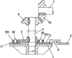
Fig. 2 is the A-A cutaway view of Fig. 1;
Fig. 3 is the top view of the utility model slide block.
The specific embodiment
Below in conjunction with accompanying drawing and concrete embodiment the utility model is described in further detail.
Fig. 1 is to shown in Figure 3, a kind of cam feed mechanism that is loaded on the forcing press side, comprise the holder 1 that is arranged on the forcing press side, charging ram 2, the upper surface of holder 1 is provided with the track 11 that is parallel to feed direction, holder 1 in the middle of the track 11 is provided with the axis hole 12 perpendicular to the holder upper surface, one slide block 3 is housed on the described track 11, the centre of slide block 3 is processed with slotted hole 31, the slotted hole 31 that one vertical shaft 4 passes slide block 3 is contained on the axis hole 12 of holder 1, vertical shaft 4 is fixed a cam 5 in the upper end surface near slide block 3, each fixes a bearing pin 32 that parallels with vertical shaft 4 on the slide block 3 of cam 5 both sides, 33, two bearing pins 32, roller 321 respectively is housed on 33,331 match with cam 5, the upper end of vertical shaft 4 is by a pair of angular wheel 6,61 are connected with the main shaft 7 of forcing press, slide block 3 fixes with a hooked scarf 8 first, and hooked scarf 8 is connected with charging ram 2 again.
During the utility model work, vertical shaft 4 is by a pair of angular wheel 6,61 rotate synchronously with the main shaft 7 of forcing press, vertical shaft 4 is with moving cam 5 to rotate again, when the short end part of cam 5 matches with roller 331, push rod 2 retreats into the leftmost side, this moment, workpiece 10 was sent into from long rails, cam 5 continues rotation, promoting slide block 3 by roller 331 further moves to right by hooked scarf 8 promotion charging rams 2, charging ram 2 just promotes workpiece 10 and moves to right, when the long end part of cam 5 matches with roller 331, workpiece 10 is pulled to right-most position, be in the stamping position that the workpiece 10 of the rightmost side just enters forcing press this moment, so circulation keeps sending the punching press cadence synchronization of rhythm and the forcing press of workpiece.
Below only be preferred embodiment of the utility model, the change that those skilled in the art does to be equal to by claim all falls into the protection domain of this case.
Claims (2)
1. cam feed mechanism that is loaded on the forcing press side, comprise the holder that is arranged on the forcing press side, charging ram, it is characterized in that: the upper surface of holder is provided with the track that is parallel to feed direction, holder in the middle of the track is provided with the axis hole perpendicular to the holder upper surface, one slide block is housed on the described track, the centre of slide block is provided with slotted hole, the slotted hole that one vertical shaft passes slide block is contained on the axis hole of holder, vertical shaft is fixed a cam in the upper end surface near slide block, each fixes a bearing pin that parallels with vertical shaft on the slide block of cam both sides, on two bearing pins roller being housed respectively matches with cam, the upper end of vertical shaft is connected with the main shaft of forcing press by a pair of angular wheel, and slide block is connected with charging ram.
2. a kind of cam feed mechanism that is loaded on the forcing press side according to claim 1, it is characterized in that: described slide block is to be connected with charging ram by a hooked scarf.
Priority Applications (1)
| Application Number | Priority Date | Filing Date | Title |
|---|---|---|---|
| CN 201220549216 CN202846945U (en) | 2012-10-25 | 2012-10-25 | Cam feeding mechanism installed on side surface of press machine |
Applications Claiming Priority (1)
| Application Number | Priority Date | Filing Date | Title |
|---|---|---|---|
| CN 201220549216 CN202846945U (en) | 2012-10-25 | 2012-10-25 | Cam feeding mechanism installed on side surface of press machine |
Publications (1)
| Publication Number | Publication Date |
|---|---|
| CN202846945U true CN202846945U (en) | 2013-04-03 |
Family
ID=47978179
Family Applications (1)
| Application Number | Title | Priority Date | Filing Date |
|---|---|---|---|
| CN 201220549216 Expired - Fee Related CN202846945U (en) | 2012-10-25 | 2012-10-25 | Cam feeding mechanism installed on side surface of press machine |
Country Status (1)
| Country | Link |
|---|---|
| CN (1) | CN202846945U (en) |
Cited By (3)
| Publication number | Priority date | Publication date | Assignee | Title |
|---|---|---|---|---|
| CN105414374A (en) * | 2015-12-14 | 2016-03-23 | 苏州源硕精密模具有限公司 | Cam feeding mechanism |
| CN106079553A (en) * | 2016-08-20 | 2016-11-09 | 艾国华 | Manufacture the extruder feed arrangement of biological boiler fuel |
| CN109175209A (en) * | 2018-09-27 | 2019-01-11 | 江苏天毅冷镦股份有限公司 | Multistage cold former postposition pellet formula feeding mechanism |
-
2012
- 2012-10-25 CN CN 201220549216 patent/CN202846945U/en not_active Expired - Fee Related
Cited By (3)
| Publication number | Priority date | Publication date | Assignee | Title |
|---|---|---|---|---|
| CN105414374A (en) * | 2015-12-14 | 2016-03-23 | 苏州源硕精密模具有限公司 | Cam feeding mechanism |
| CN106079553A (en) * | 2016-08-20 | 2016-11-09 | 艾国华 | Manufacture the extruder feed arrangement of biological boiler fuel |
| CN109175209A (en) * | 2018-09-27 | 2019-01-11 | 江苏天毅冷镦股份有限公司 | Multistage cold former postposition pellet formula feeding mechanism |
Similar Documents
| Publication | Publication Date | Title |
|---|---|---|
| CN202670706U (en) | Accurate locating intermittent conveying mechanism for paper cylinder cake | |
| CN202539685U (en) | Feeding device of circular sawing machine | |
| CN203076485U (en) | Adjustable synchronous feeding mechanism of stamping device | |
| CN202846945U (en) | Cam feeding mechanism installed on side surface of press machine | |
| CN202782116U (en) | High-and-low adjustment device of roller | |
| CN102689454A (en) | Screw rod type pushing device comprising linear guide rails | |
| CN203864059U (en) | Press machine sliding block guiding clearance adjusting device | |
| CN207027248U (en) | A kind of filament cutter sharpening reciprocator | |
| CN203409857U (en) | Overturning press plate mechanism driven by screw rod | |
| CN204953788U (en) | Adopt transmission system of servo press of many motor drive of different belts | |
| CN203206666U (en) | A fully-electric pedestal apparatus of a horizontal wire jumper plug-in machine | |
| CN203445399U (en) | Fully-automatic wire cutting, stripping and end-punching machine | |
| CN103786058A (en) | Moving mechanism | |
| CN202591619U (en) | Opening flattening machine used for processing end faces of steel tubes | |
| CN204414622U (en) | Disc cam drive-type double-station punching device | |
| CN203401577U (en) | Bevel gear rocker arm blank pushing mechanism of blank cutting machine | |
| CN202727805U (en) | Tip driving device of large three-dimensional carving machine | |
| CN203568558U (en) | Delivery system applied to paper financial products | |
| CN203888055U (en) | Open mill with overload protection distance adjusting device | |
| CN203330821U (en) | Grinding and polishing advancing and fixture position switching mechanism of full-automatic rhinestone grinding and polishing machine | |
| CN201950137U (en) | Steel pipe clamping rotating conveying device | |
| CN202763451U (en) | Engine cylinder block finish-milling bearing score actinal surface combined machine tool | |
| CN104649063A (en) | Outgoing system applied to paper financial product | |
| CN203751815U (en) | Travel mechanism | |
| CN104589808A (en) | Conveying rail for feeding device of bearing marking machine |
Legal Events
| Date | Code | Title | Description |
|---|---|---|---|
| C14 | Grant of patent or utility model | ||
| GR01 | Patent grant | ||
| CF01 | Termination of patent right due to non-payment of annual fee |
Granted publication date: 20130403 Termination date: 20151025 |
|
| EXPY | Termination of patent right or utility model |