CN202808572U - Device for manufacturing glass sheet bars - Google Patents
Device for manufacturing glass sheet bars Download PDFInfo
- Publication number
- CN202808572U CN202808572U CN2012204192702U CN201220419270U CN202808572U CN 202808572 U CN202808572 U CN 202808572U CN 2012204192702 U CN2012204192702 U CN 2012204192702U CN 201220419270 U CN201220419270 U CN 201220419270U CN 202808572 U CN202808572 U CN 202808572U
- Authority
- CN
- China
- Prior art keywords
- glass ribbon
- glass
- weight
- ribbon
- length
- Prior art date
- Legal status (The legal status is an assumption and is not a legal conclusion. Google has not performed a legal analysis and makes no representation as to the accuracy of the status listed.)
- Expired - Fee Related
Links
Images


Classifications
-
- C—CHEMISTRY; METALLURGY
- C03—GLASS; MINERAL OR SLAG WOOL
- C03B—MANUFACTURE, SHAPING, OR SUPPLEMENTARY PROCESSES
- C03B17/00—Forming molten glass by flowing-out, pushing-out, extruding or drawing downwardly or laterally from forming slits or by overflowing over lips
- C03B17/06—Forming glass sheets
-
- C—CHEMISTRY; METALLURGY
- C03—GLASS; MINERAL OR SLAG WOOL
- C03B—MANUFACTURE, SHAPING, OR SUPPLEMENTARY PROCESSES
- C03B21/00—Severing glass sheets, tubes or rods while still plastic
- C03B21/02—Severing glass sheets, tubes or rods while still plastic by cutting
-
- C—CHEMISTRY; METALLURGY
- C03—GLASS; MINERAL OR SLAG WOOL
- C03B—MANUFACTURE, SHAPING, OR SUPPLEMENTARY PROCESSES
- C03B18/00—Shaping glass in contact with the surface of a liquid
- C03B18/02—Forming sheets
-
- C—CHEMISTRY; METALLURGY
- C03—GLASS; MINERAL OR SLAG WOOL
- C03B—MANUFACTURE, SHAPING, OR SUPPLEMENTARY PROCESSES
- C03B18/00—Shaping glass in contact with the surface of a liquid
- C03B18/02—Forming sheets
- C03B18/04—Changing or regulating the dimensions of the molten glass ribbon
-
- C—CHEMISTRY; METALLURGY
- C03—GLASS; MINERAL OR SLAG WOOL
- C03B—MANUFACTURE, SHAPING, OR SUPPLEMENTARY PROCESSES
- C03B21/00—Severing glass sheets, tubes or rods while still plastic
-
- C—CHEMISTRY; METALLURGY
- C03—GLASS; MINERAL OR SLAG WOOL
- C03B—MANUFACTURE, SHAPING, OR SUPPLEMENTARY PROCESSES
- C03B33/00—Severing cooled glass
- C03B33/02—Cutting or splitting sheet glass or ribbons; Apparatus or machines therefor
- C03B33/0215—Cutting or splitting sheet glass or ribbons; Apparatus or machines therefor the ribbon being in a substantially vertical plane
-
- B—PERFORMING OPERATIONS; TRANSPORTING
- B65—CONVEYING; PACKING; STORING; HANDLING THIN OR FILAMENTARY MATERIAL
- B65G—TRANSPORT OR STORAGE DEVICES, e.g. CONVEYORS FOR LOADING OR TIPPING, SHOP CONVEYOR SYSTEMS OR PNEUMATIC TUBE CONVEYORS
- B65G2249/00—Aspects relating to conveying systems for the manufacture of fragile sheets
- B65G2249/04—Arrangements of vacuum systems or suction cups
Abstract
The utility model relates to a device for manufacturing glass sheet bars, comprising a forming body which is used for forming glass tapes from the molten glass, and a weight compensation device which is used for applying force on the glass tapes. The weight compensation device comprises a liner driving unit, a driving motor which is coupled to the liner driving unit, and a meshing device which is coupled to the liner driving unit, wherein the meshing device comprises a suction cup which is used for contacting the glass tapes. The weight consumption device is made into a structure which applies a downward force onto the glass tapes, wherein the downward force is in inverse ratio with the length of the glass tapes. Therefore, when the weight of the glass tapes is increased, the force applied onto the glass tapes by the weight compensation device becomes smaller.
Description
The mutual reference of related application
The U.S. Provisional Patent Application series number 61/526 that the application requires submission on August 23rd, 2011 according to 35U.S.C. § 119,367 senior interest, and the U.S. Patent Application Serial 13/303 that 120 requirements were submitted on November 23rd, 2011 according to 35U.S.C. §, 732 senior interest, this paper is to introduce its content referring to mode.
Technical field
The utility model relates to the device of from mobile glass ribbon cutting or separation of glasses plate, and especially, in the partitioning cycle process, the weight that changes by the compensation glass band guarantees the orientation that glass ribbon is stable.
Background technology
Downdraw process as melting-pulling technique can be produced continuous glass ribbon, and when glass descended from molding, glass ribbon was Hookean body from the glass formation material transition of viscous just.When the length of glass ribbon increases, just arrived cutting unit cuts (separation) glass sheet from glass ribbon the moment, thus, shorten glass ribbon with the length of glass sheet.Except shortening glass ribbon, also reduce the weight of glass ribbon with the weight of the glass sheet that separates.
In the typical down draw process process that is being used for producing display screen used glass sheet in making, importantly, reduce as far as possible to form the contact between all parts of glass ribbon of a display screen part thereafter, i.e. the quality region of so-called glass ribbon.Therefore, for reducing contact, only in edge's operation of glass ribbon, this edge will be removed later usually.Therefore, pull device and just moderately retrain glass ribbon.Specifically, glass sheet downcuts from glass ribbon, and when glass ribbon device to be cut when engagement, the free end of glass ribbon is freely suspended from the supporting member of upstream.When glass sheet downcut from the free end of glass ribbon, the unexpected minimizing of weight that occurs when glass sheet is removed can cause the free end of new formation and the new shape that jumps out.The flip-flop of this shape can be propagated by glass ribbon in the upstream, and upsets the process that pulls.For example, the pulling force that acts on the glass ribbon that the upstream pulls the roller generation can be interrupted, and when glass passes through the transformetion range of glass, along with glass ribbon changes solid into from viscous liquid, can bring out stress and enter in the glass ribbon.The method and apparatus of compensation glass band changes in weight can reduce or eliminate the source of this process discordance as much as possible.
The utility model content
As the glass ribbon of continuous moving, for example, by the glass ribbon that continuous drop-down melten glass from container forms, the shape temporal evolution of this glass ribbon.That is, when glass ribbon length was elongated, the weight of glass ribbon just increased.Therefore, glass ribbon is tending towards passing in time and longitudinally flattens, until remove glass sheet from glass ribbon.Because the glass ribbon of a part is freely suspended, therefore, when removing glass sheet from glass ribbon, the weight of glass sheet also is removed, and the power of the glass ribbon that is tending towards longitudinally flattening suddenly is reduced or eliminates.The resultant movement of glass ribbon can have been brought out the perturbation that enters in the glass ribbon, and this kind perturbation can be interrupted the glass ribbon part of the upstream end in the place that glass sheet removes from glass ribbon.For example, these perturbations can affect glass ribbon negatively glass ribbon is converted to the glass ribbon part of Hookean body from viscous liquid in.A potential effect can be freezing of stress.Other effect comprises that the pulling force that is applied on the glass ribbon interrupts.
According to embodiment described below, weight compensation means has been described, glass ribbon weight can be compensated by this weight compensation means over time the preceding.
Therefore, disclosed the device of making glass sheet, this device comprises: the molding that is used for forming from melten glass glass ribbon; Be used for the weight compensation means to the glass ribbon application of force, this weight compensation means comprises: linear drive unit; Be coupled to the CD-ROM drive motor of linear drive unit; Be coupled to the geared assembly of linear drive unit, this geared assembly comprises the suction cup for the contact glass ribbon; And wherein, weight compensation means is configured to downward force is applied on the glass ribbon, and this downward force is inversely proportional to the length of glass ribbon.Geared assembly can comprise actuator, its be configured to mobile suction cup towards or away from glass ribbon.In certain embodiments, this device can comprise a plurality of weight compensation means.Molding preferably comprises in the upper surface that is formed on molding in order to admitting the passage of melten glass, and the convergence profiled surface that is connected to the root place.The melten glass that overflows conduit wall flows at the profiled surface of assembling, and they are as independent the flowing of uniting at the root place of molding again or fusing.
In the following detailed description, other feature and advantage of the utility model will be set forth, those skilled in the art will partly understand to these feature and advantage from this is described easily, or be familiar with them by putting into practice utility model as described herein, utility model described herein comprises following detailed description, claims and accompanying drawing.
Should be understood that above generality is described and following detailed description has provided embodiment of the present utility model, these embodiment are used to provide general introduction or the framework for the usefulness of understanding characteristic that the utility model advocates and feature.Including in of accompanying drawing aims to provide further understanding of the present utility model, and accompanying drawing consists of the part of this specification sheets.Accompanying drawing shows the various embodiment of the utility model, is used for explaining principle of the present utility model and operation together with describing.
Description of drawings
Fig. 1 is the front view of the glass making system of demonstration;
Fig. 2 is the front view of the glass making system of Fig. 1, and the parts of the system that pulls the roller downstream are shown;
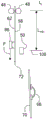
Fig. 3 is according to the mobile anvil machine of the utility model one embodiment and the frontview of weight compensation means;
Fig. 4 illustrates the outline map of the various longitudinal shapes of glass ribbon of continuous moving when glass ribbon length increases;
Fig. 5 is the frontview of Fig. 2 device, controls movement is shown and the parts of the power that applied by the weight compensation means of Fig. 3;
Fig. 6 A-6F illustrates each stage of the glass ribbon cutting circulation of demonstration, and its edge from glass ribbon is watched.
Embodiment
In the following detailed description, for the purpose explained and will not limit, set forth the embodiment that discloses the example of detail, to provide thorough of the present utility model.Yet those skilled in the art are from will be appreciated that after benefiting the disclosure of the present utility model, and the utility model also can be applicable among other embodiment that departs from mutually with disclosed here detail.In addition, can be omitted the description of well-known device, method and material, so that more clear to description of the present utility model.At last, in any applicable situation, identical Reference numeral represents identical element.
Fig. 1 illustrates the example embodiment of the melten glass manufacturing system 10 that is used to form glass sheet, this system comprises smelting furnace 12, refining vessel 14, stirred vessel 16, admits container 18, downspout conductor 20, entrance 22 and molding 24, and the thin continuous moving glass ribbon 26 that the glass of melting forms material descends from this molding 24.Glass making system 10 comprises that also various other containers or be used for transmit the conduit that melten glass forms material, comprise smelting furnace to the pipe connecting 28 between the refining vessel, refining vessel to the pipe connecting 30 between the stirred vessel and stirred vessel to the pipe connecting 32 of admitting between the container.When smelting furnace and molding typically by such as comprise aluminum oxide or or the such stupalith of zirconic ceramic tile when forming, various containers and pipeline therebetween often comprise platinum or platinum alloy.Although following description relates to fusion downdraw system and the process of demonstration, all in this way systems shown in Figure 1, but the utility model is equally applicable to pull such as the drop-down glass manufacturing process of single-sided overflow process or slit other variant of process, and these processes are for the technician is known in the art.
Demonstration melting process according to Fig. 1 offers smelting furnace 12 with admixtion 36, and is as shown in arrow 38, and admixtion 36 installs in the stove 12, and fusing and produce glass and form material (below be called melten glass 40) in stove.Melten glass 40 is transferred to refining vessel 14 to the pipe connecting 28 between the refining vessel from smelting furnace 12 by smelting furnace.Melten glass is heated to the temperature above furnace temperature in refining vessel 14, so the multivalence oxide material that is contained in the melten glass discharges oxygen, oxygen rises by melten glass.The high temperature of this oxygen discharges and helps to remove the interior small bubbles of melten glass that batch melting produces.
Then, melten glass 14 flows in the stirred vessels 16 to the pipe connecting 30 between the stirred vessel from refining vessel by refining vessel, and there, the agitator of rotation mixes and this melten glass that homogenizes, to guarantee uniform consistence.Then the melten glass that homogenizes that flows out from stirred vessel 16 flows through stirred vessel to the pipe connecting 32 of admitting the container, it is collected in admits in the container 18, and flow to molding 24 by downspout conductor 20 and entrance 22, there, melten glass forms glass ribbon.
For glass sheet is separated, can adopt the anvil machine (TAM) 50 of movement as shown in Figure 2 from glass ribbon.In typical structural arrangement, as by means of Fig. 3 clearly shown in, this TAM50 comprises anvil or backing rod 52 and scratching device 54.For example, scratching device 54 can comprise all tracing wheels 56 as shown in Figure 3, and it contacts glass ribbon 26, and traverses the width of glass ribbon or the width of a part, and the first major surfaces 58 of glass ribbon is applied power and forms line of weakness 60.As the name indication, one side of the glass ribbon that the second major surfaces 62(of anvil or 52 pairs of glass ribbons of backing rod is relative with that side that is carved with line of weakness) provides counter-force, thus, when tracing wheel along width or when laterally crossing glass ribbon and moving, so that the movement of glass ribbon is minimum.Therefore, in operation, on the surface or side of the glass ribbon relative with that side of glass ribbon of line of weakness formation, backing rod contact glass ribbon.In the time course that cutting operation does not occur, scratching device 54 and backing rod 52 can be recalled away from glass ribbon.
Because glass ribbon 26 is mobile in the indentation process, so TAM50 moves with glass ribbon, so that formation is perpendicular to the line of weakness 60 at glass ribbon edge 64.That is, glass ribbon moves with certain velocity vector V, and velocity vector V comprises scalar value (speed) and direction, and scalar value is partly determined by the velocity of rotation that pulls roller.For the purpose of further discussing, suppose that the perpendicular direction of V is downward, but in certain embodiments, this direction also can be different, for example, depart from one or more groups roller.
Do not have relative movement in order to ensure TAM50 in the indentation process and glass ribbon 26, TAM50 is configured to move with speed and the direction of velocity vector S representative, and this velocity vector S is identical or basic identical with the velocity vector V of glass ribbon.Therefore, the width that scratching device 54 traverses band moves, on the travel direction of glass ribbon, the moving downward and TAM(and tracing wheel thus of band, or other indentation parts) move downward between there is no velocity contrast.That is, scratching device 54 can produce the line of weakness transverse to direction of belt travel.
When line of weakness was finished, a plurality of suction cup 68 engagements of robot 66 usefulness were with respect to the part of the glass ribbon in the line of weakness downstream of direction of belt travel, and the edge applies moment of flexure perpendicular to the direction with major surfaces to glass ribbon.Preferably, robot 66 with by the upper glass ribbon that contacts of the backing rod 52 same major surfacess that contacts (that is, the second major surfaces 62).The moment of flexure that robot 66 causes produces tensile stress at line of weakness 60, and it causes at line of weakness place formation crackle.This crack propagation thus, makes glass sheet separate from glass ribbon by the thickness of glass ribbon.Backing rod 52 and adoptable any additional protruding rod that contacts, then with the glass ribbon throw out of gear, TAM50 upstream moves to its zero position, prepares another cutting circulation.Except the backing rod, TAM50 can comprise one or more stabilization rod (protruding rod), stabilization rod is at upstream or the downstream contact glass ribbon of backing rod, both can be on glass sheet that side (first major surfaces 58) identical with the backing rod, also can be on glass sheet that side (second major surfaces 62) relative with the backing rod, the contact glass ribbon, with the motion that further makes backing rod or protruding rod below with upwards keep apart towards the propagation in the viscous elasticity zone of glass ribbon.For the purpose of further discussing, TAM will be referred to as the TAM stroke in cutting cycle period along the range of movement of direction of belt travel.Therefore, as at random selecting here, the cutting circulation just glass sheet from after glass ribbon 26 is removed and TAM50 moved on the top of its stroke.Should be noted that the TAM stroke does not need to equal the glass sheet length that will separate from glass ribbon, and can be less than the length of glass sheet.
In when beginning cutting circulation, with respect to the root 46 of molding 24, glass ribbon is for the shortest or near minimum length, the glass sheet 70(that removes predetermined length sees Fig. 6 D and 6E) operation just occur.In addition, the weight with respect to the glass ribbon of given reference point also is minimum.For example, if pull roller 48 at the free end 72 of glass ribbon 26 and the minimum point of contact between this point of contact, then the glass ribbon weight on the length of this band is minimum.Can have additional roller, but they locate lowlyer than the pulling roller of the weight of supporting glass band, so using pulling roller as a reference point is arbitrarily, used here is in order to illustrate rather than to be limited.Really, the length of glass ribbon can be with respect to any arbitrarily reference point, for example, and the root of molding.Can say fully, along between the free end 72 length of glass ribbon 26, at the glass ribbon of the root 46 of molding 24 and continuous moving and comprise this root certain place a bit, have the structure of contact glass ribbon, but the weight of the weight of this structure supporting glass band or a part, distance between this structure and the glass ribbon free end is representing weight, and this weight is based on the glass density that forms glass ribbon and the size of glass ribbon.Because glass ribbon upgrades from molding continuously and therefore moves down continuously, so, selected reference point below also terminates in the length of the glass ribbon of glass ribbon free end, increasing continuously in cutting interim, " free length " that this length is referred to as glass ribbon hereinafter (FL).Owing to ever-increasing free length is arranged, so the weight that increases continuously relevant with free length is just arranged, hereinafter is called " free weight " (FW).That is, free length and free weight in the cutting circulation begins all are minimum, and basically stably increase, until glass sheet separates from glass ribbon, at this moment, free length and free weight turn back to the minimum value of each.Just the moment before glass sheet separates from the glass ribbon of continuous moving, free length and free weight be maximum (for the purpose of discussion, all not considering with load or weight that the contacted robot of the free length of glass ribbon presents).Free length is minimum at glass sheet from the moment that glass ribbon separates, and the moment before glass sheet separates from glass ribbon is maximum.Therefore, free length FL can use L
Min+ Δ L represents, wherein, and L
MinThe minimum length of free length, the variation in the Δ L stands for freedom length, it also is the length of the glass sheet that will separate from glass ribbon.Similarly, free weight FW can use W
Min+ Δ W represents, wherein, and W
MinThe minimum weight of free length, the variation in the Δ W stands for freedom weight, it also is the weight of the glass sheet that will separate from glass ribbon.Therefore, Δ W
MaxWith Δ L
MaxRepresent respectively the maximum value of free weight changes delta W and the maximum value of free length changes delta L.
When free length and free weight increase, the shape of glass ribbon constantly changes.For example, glass ribbon can present crooked or curling.When free weight increased, because the increase of free weight, at least longitudinally along the length of glass ribbon, glass was with the trend of flattening.That is, when glass ribbon descended from molding, it can present many complicated shapes, and complicated shape traverses the width of band along the length of band, or the combination of both of these case, so that glass is with nonplanar overall shape.The stable free weight that increases has and reduces glass ribbon along the trend of the molded non-planar of at least length of band.Yet the free length of band is in the elastic part of band, because the cause of free weight, glass ribbon keeps special longitudinal shape.When free weight was removed suddenly, glass ribbon will present the shape that has had when not having free length.This can more easily see clearly by means of Fig. 4, and Fig. 4 illustrates the longitudinal shape of the glass ribbon during the stages of single cutting circulation, and this figure watches from the edge of glass ribbon.According to Fig. 4, the glass ribbon shape during curve 74 representative cutting circulation beginning: free length FL and free weight FW are minimum value (Δ L and Δ W equal zero).Dotted line represents the position of line of weakness 60.When free length FL and free weight FW increase, glass ribbon begins to flatten, respectively shown in curve 78 and 80.At last, just at glass sheet before line of weakness 60 places separate, free length and free weight are the maximum values of curve 82 representatives, this moment, glass ribbon was the most smooth.Yet, because at least a portion of free length is within the Hookean region of glass ribbon, so, when free length is maximum value and when dropping because of free weight, a lot of energy storage is arranged in free length.When the part of glass ribbon between line of weakness 60 and glass ribbon (glass sheet 70) free end 72 was removed, the potential energy in the glass ribbon was released, and glass ribbon jumps and gets back to the position of curve 74.As noted above, the flip-flop of this shape can cause in the upstream interruption of pulling process.
Therefore, Fig. 3 also illustrates to compensate the weight compensation means 84 of the free weight of variation, thus, and the shape of the glass ribbon that steady and continuous moves.Weight compensation means 84 comprises geared assembly 86 and the transmitter 88 of contact and engagement glass ribbon 26, and geared assembly 86 moves with velocity vector U along transmitter, and this velocity vector U is identical or basic identical with the velocity vector V of the glass ribbon of continuous moving.Should be noted that velocity vector U only is shown as downward direction.When the direction of geared assembly 86 moved up geared assembly conversely, the speed when occurring moving upward can be more a lot of soon than the scalar speed that forms velocity vector U.Also have, as hereinafter pointed, the speed that geared assembly 86 can be different from the velocity component of velocity vector V slightly moves, and is the same in the situation of glass ribbon 26 formation downward forces when mesh with glass ribbon.The difference of this speed will change with the variation of glass ribbon free weight.Although following description for single weight compensation means, also can be adopted a plurality of weight compensation means.For example, can adopt two weight compensation means to come every lateral edge portions applied load to glass ribbon.
For example, geared assembly 86 can comprise suction cup 90, and suction cup is by forming more than the soft resilient material of the glass of glass ribbon, and like this, the damage that is caused by the contact between suction cup and the glass ribbon can be minimum.Suction cup 90 can be coupled on the actuator 92, actuator configurations become to make suction cup respectively towards or extend or retract away from the major surfaces of glass ribbon.For example, actuator 92 can comprise the cylinder that is communicated with pressure air source (not shown) fluid ground.Perhaps, actuator 92 can comprise hydro-cylinder or o.
Geared assembly 86 preferably also comprises the load-sensing unit (not shown), is used for measuring the torque T between glass ribbon and the geared assembly
q
Geared assembly 86 is coupled to transmitter 88.Transmitter 88 comprises track or linear driver element 94 and CD-ROM drive motor 96.CD-ROM drive motor 96 for example can be servomotor.CD-ROM drive motor 96 is coupled to linear driver element 94, and they provide the control of motion and moment of torsion together to geared assembly 86 according to the instruction (see figure 5) of control unit 98.Control unit 98 can be calculating device, all in this way multi-purpose computers or out of Memory treatment unit, and it is receiving course input and sending control signal from pulling equipment, and control signal changes the actuating speed of linear drive unit 94 by CD-ROM drive motor 96.
As shown in Figure 5, control unit 98 can be configured to receive the velocity of rotation that pulls roller, the velocity of rotation of one or more other rollers that contact with the glass ribbon of continuous moving), velocity of rotation for example can obtain from bring the encoder that pulls in the roller into, and by control line 100 it is provided to control unit 98.Then control unit 98 can calculate the linear speed of the glass ribbon of continuous moving from the velocity of rotation that pulls roller.Yet, also can adopt other method of known acquisition glass ribbon linear speed in the row.
In certain embodiments, pulling roller (or other roller that contacts with glass ribbon) can be configured to provide torque value to control unit 98.For example, pull the torque T that the roller place forms
qCan be used to determine in esse (instantaneous) glass ribbon weight, rather than come definite weight based on the length of calculating (itself is based on the speed of glass ribbon).In addition, control unit 98 can be used to control by control line 104 operation of TAM 50, comes control 66 by control line 106.
With reference to Fig. 6 A-6F, now circulate to describe the operation of weight compensation means 84 by a complete cutting, this cutting circulation at random starts from sometime point, at this moment, glass ribbon is just removed from the glass ribbon of continuous moving, and TAM and weight compensation means all are in their corresponding starting positions.In order to describe the operation of TAM and weight compensation means, the position of TAM 50 when the cutting circulation begins is called zero position 108, this position is that TAM50 is at the upstream position of going up most at place, TAM stroke summit; The position of geared assembly 86 will be called original position 110, and it is the upstream position of going up most of geared assembly.With regard to the time, the time during cutting circulation beginning is arbitrarily designated as t1.
For the ease of discussing, can consider to ignore the return interval of TAM50 and geared assembly 86.In the practice, it is limited allowing return interval.That is, for example, although during return interval, TAM is at the limited time quantum of the mobile cost of whole strokes of device, and for the purpose of discussing, this return interval and inertia (reaching influence time at full speed) are ignored it with consideration.
At time t
1Beginning, and with reference to Fig. 5 and 6A, the geared assembly 86 of weight compensation means 84 and glass ribbon 26 engagements, and move down with the velocity vector U of the velocity vector V that is substantially equal to glass ribbon 26.That is, start actuator 92, stretch out suction cup 90 towards glass ribbon 26.Vacuum is applied to suction cup 90.When suction cup 90 contact glass ribbon 26, suction cup 90 and glass ribbon 26 engagements so that downward force F is applied on the glass ribbon, do not make suction cup 90 lose contact or change position (slip).The CD-ROM drive motor 96 of controlled unit 98 controls moves geared assembly 86 by the driver element 94 of linearity.Simultaneously, include dynamometry unit inspection in the geared assembly 86 in to the suffered torque T of geared assembly
q, and by control line 102 the moment of torsion amplitude is offered control unit 98.Control unit 98 is with torque T
qBe converted into downward force F of equal value, after this, control unit control CD-ROM drive motor 96, so that the downward force F that geared assembly applies equals preset value, for example, Δ W.Preferably, in free length be the t of minimum value
1The time downward force F and Δ W
MaxIdentical or almost identical.In other words, the purposes of weight compensation means 84 is the variations (that is, Δ W) in the compensation free weight, and when Δ L=0, weight compensation means applies maximum, force, and at Δ L
MaxThe time apply minimum force.In a preferred embodiment, Δ W
MaxThe weight of the glass sheet from glass ribbon, removed.That is because the length of glass ribbon is definite by process (for example, client's technical specification book), so, the weight of glass sheet be scheduled to known, or can estimate well at least.Yet, Δ W
MaxCan greater than or in some cases less than the predetermined weight of the glass sheet that will be removed.For example, this can occur during to the glass sheet of producing the length be different from previous glass sheet at process change, but is not changed by the load that weight compensation means applies.When the glass ribbon of continuous moving moved down, free length and Δ W thus increased, and control unit 98 control CD-ROM drive motors 96 are so that the load that is applied by geared assembly 86 reduces pro rata.In addition, relative although TAM 50 is illustrated as the single side that is arranged to glass ribbon 26, in practice, TAM 50 or its part also can be arranged on the both sides of glass ribbon.This can be self-evident, because indentation occurs on the side of glass ribbon, and the backing rod is arranged in the opposite of scratching device.
Shown in Fig. 6 B, at t
2Place's beginning, and also with reference to Fig. 5, the free length of glass ribbon continues to increase Δ L, and line of weakness position 114 is near the position of TAM 50.When the sufficient length of glass ribbon was passed through TAM 50, this TAM 50 just was adjacent to desired line of weakness position 114, TAM 50 and glass ribbon 26 engagements.(in the future) indent locations thereafter of next glass sheet is produced in position 116 representatives.
Shown in Fig. 6 C, at time t
3Place's beginning, and also with reference to Fig. 5, when free end 72 arrived preposition, at this moment, free length and free weight thus reached maximum value (Δ L=Δ L
Max, Δ W=Δ W
Max), and reach minimum value (F for minimum) by the load that weight compensation means 84 applies, geared assembly 86 and glass ribbon 26 throw out of gear, and turn back to original position 110.Robot 66 and glass ribbon 26 engagements, the width that scratching device 54 traverses glass ribbon begins indentation, produces line of weakness 60.Glass ribbon 26 engagements of robot 66 below line of weakness 60.
Shown in Fig. 6 D, at time t
4Place's beginning, robot 66 traverses line of weakness 60 and applies bending force.This bending force shows as tensile stress, and tensile stress forms crackle at the line of weakness place, and crackle traverses glass ribbon and propagates through glass ribbon.
Referring now to Fig. 6 E, at time t
5Place's beginning, geared assembly 86 meshes with glass ribbon 26, and moves with velocity vector U, and this velocity vector U is identical or roughly the same with the velocity vector V of glass ribbon 26.At that time, robot 66 removes the glass sheet 70 of separating.
At last, shown in Fig. 6 F, at time t
6The place, TAM 50 throws off the engagement with glass ribbon 26, and is moved back into zero position 108, and geared assembly 86 provides maximum downward force F.
According to disclosed utility model, those skilled in the art will be understood that, pull equipment and operation for special glass, and the order of above-mentioned variety of event and time can revise, and said sequence only is a kind of description to exemplary order.
Those skilled in the art will be appreciated that, also can make various modifications and variations to the utility model, and can not break away from spirit and scope of the present utility model.Therefore, the utility model is intended to contain these to modifications and variations of the present utility model, as long as they fall within the scope of attached claims and its Equivalent.
Claims (4)
1. a device of making glass sheet is characterized in that, this device comprises:
Be used for forming from melten glass the molding of glass ribbon;
Be used for the weight compensation means to the glass ribbon application of force, this weight compensation means comprises:
Linear drive unit;
Be coupled to the CD-ROM drive motor of linear drive unit;
Be coupled to the geared assembly of linear drive unit, this geared assembly comprises the suction cup for the contact glass ribbon; And
Wherein, weight compensation means is configured to downward force is applied on the glass ribbon, and this downward force is inversely proportional to the length of glass ribbon.
2. device as claimed in claim 1 is characterized in that, described geared assembly comprises actuator, described actuator configurations become mobile suction cup towards or away from glass ribbon.
3. device as claimed in claim 1 is characterized in that, this device comprises a plurality of weight compensation means.
4. device as claimed in claim 1 is characterized in that, described molding comprises in the upper surface that is formed on molding in order to admitting the passage of melten glass, and the profiled surface that is connected to the convergence at root place.
Applications Claiming Priority (4)
| Application Number | Priority Date | Filing Date | Title |
|---|---|---|---|
| US201161526367P | 2011-08-23 | 2011-08-23 | |
| US61/526,367 | 2011-08-23 | ||
| US13/303,732 US8794036B2 (en) | 2011-08-23 | 2011-11-23 | Apparatus and method for separating a glass sheet from a moving ribbon of glass |
| US13/303,732 | 2011-11-23 |
Publications (1)
| Publication Number | Publication Date |
|---|---|
| CN202808572U true CN202808572U (en) | 2013-03-20 |
Family
ID=47741678
Family Applications (2)
| Application Number | Title | Priority Date | Filing Date |
|---|---|---|---|
| CN2012204192702U Expired - Fee Related CN202808572U (en) | 2011-08-23 | 2012-08-22 | Device for manufacturing glass sheet bars |
| CN201210300859.5A Expired - Fee Related CN102951783B (en) | 2011-08-23 | 2012-08-22 | Apparatus and method for separating glass sheet from moving ribbon of glass |
Family Applications After (1)
| Application Number | Title | Priority Date | Filing Date |
|---|---|---|---|
| CN201210300859.5A Expired - Fee Related CN102951783B (en) | 2011-08-23 | 2012-08-22 | Apparatus and method for separating glass sheet from moving ribbon of glass |
Country Status (5)
| Country | Link |
|---|---|
| US (2) | US8794036B2 (en) |
| JP (2) | JP5936486B2 (en) |
| KR (1) | KR20130023128A (en) |
| CN (2) | CN202808572U (en) |
| TW (2) | TWI543944B (en) |
Cited By (1)
| Publication number | Priority date | Publication date | Assignee | Title |
|---|---|---|---|---|
| CN102951783A (en) * | 2011-08-23 | 2013-03-06 | 康宁股份有限公司 | Apparatus and method for separating glass sheet from moving ribbon of glass |
Families Citing this family (23)
| Publication number | Priority date | Publication date | Assignee | Title |
|---|---|---|---|---|
| US9038418B2 (en) * | 2012-09-25 | 2015-05-26 | Corning Incorporated | Apparatuses for manufacturing glass and methods of managing pulling forces applied to glass ribbon |
| WO2014209833A1 (en) * | 2013-06-25 | 2014-12-31 | Corning Incorporated | Method and apparatus for separating a glass sheet from a moving ribbon of glass |
| WO2016037343A1 (en) * | 2014-09-12 | 2016-03-17 | Schott Glass Technologies (Suzhou) Co. Ltd. | Ultrathin chemically toughened glass article and method for producing such a glass article |
| JP6488107B2 (en) * | 2014-10-31 | 2019-03-20 | AvanStrate株式会社 | Glass plate manufacturing method and glass plate manufacturing apparatus |
| JP6529805B2 (en) * | 2015-03-31 | 2019-06-12 | AvanStrate株式会社 | Method of manufacturing glass plate, and apparatus for manufacturing glass plate |
| US20180148365A1 (en) * | 2015-04-22 | 2018-05-31 | Corning Incorporated | Glass manufacturing apparatus facilitating separation of a glass ribbon |
| US10793462B2 (en) * | 2015-07-07 | 2020-10-06 | Corning Incorporated | Apparatuses and methods for heating moving glass ribbons at separation lines and/or for separating glass sheets from glass ribbons |
| TW201728540A (en) * | 2015-11-05 | 2017-08-16 | 康寧公司 | Glass manufacturing method for reduced particle adhesion |
| JP6628032B2 (en) * | 2015-12-21 | 2020-01-08 | 日本電気硝子株式会社 | Glass plate manufacturing equipment |
| JP6589620B2 (en) * | 2015-12-21 | 2019-10-16 | 日本電気硝子株式会社 | Glass plate manufacturing equipment |
| JP6674138B2 (en) * | 2016-05-12 | 2020-04-01 | 日本電気硝子株式会社 | Glass plate manufacturing apparatus and glass plate manufacturing method |
| KR102499831B1 (en) * | 2016-05-23 | 2023-02-14 | 코닝 인코포레이티드 | Method of predicting gravity-free shape of glass sheet and method of managing quality of a glass sheet based on gravity-free shape |
| JP6647680B2 (en) * | 2016-05-31 | 2020-02-14 | 日本電気硝子株式会社 | Method and apparatus for manufacturing glass plate |
| JP6757496B2 (en) * | 2016-12-02 | 2020-09-23 | 日本電気硝子株式会社 | Manufacturing method of glass plate |
| TW201906704A (en) * | 2017-06-26 | 2019-02-16 | 美商康寧公司 | Apparatus and method for sheet separation with tensile strength measurement |
| KR20200131907A (en) * | 2018-04-12 | 2020-11-24 | 코닝 인코포레이티드 | Apparatus and method for bonding with a moving glass ribbon |
| JP7320534B2 (en) | 2018-05-14 | 2023-08-03 | コーニング インコーポレイテッド | Apparatus and method for processing glass sheets |
| KR20200133090A (en) * | 2019-05-16 | 2020-11-26 | 코닝 인코포레이티드 | Apparatus For manufacturing a Glass ribbon |
| WO2021055404A1 (en) * | 2019-09-20 | 2021-03-25 | Corning Incorporated | Methods and apparatus for forming a glass ribbon |
| JP2022093901A (en) * | 2020-12-14 | 2022-06-24 | 日本電気硝子株式会社 | Method and apparatus for manufacturing glass plate |
| CN114014015B (en) * | 2021-11-16 | 2022-09-06 | 秦皇岛玻璃工业研究设计院有限公司 | Conveying line and conveying method for sheet glass cold end production |
| CN115057233B (en) * | 2022-06-09 | 2024-01-09 | 河北光兴半导体技术有限公司 | Breaking device and breaking method |
| CN114956537B (en) * | 2022-06-30 | 2023-08-01 | 苏州迅益科系统科技有限公司 | Flexible glass transverse cutting and breaking device and breaking method thereof |
Family Cites Families (29)
| Publication number | Priority date | Publication date | Assignee | Title |
|---|---|---|---|---|
| US1565307A (en) * | 1923-12-26 | 1925-12-15 | Libbey Owens Sheet Glass Co | Drawing sheet glass |
| US3149949A (en) * | 1961-02-27 | 1964-09-22 | Corning Glass Works | Downflow sheet drawing method and apparatus |
| DE19918936A1 (en) * | 1999-04-27 | 2000-11-02 | Schott Glas | Method and device for producing single glass panes |
| JP3586142B2 (en) * | 1999-07-22 | 2004-11-10 | エヌエッチ・テクノグラス株式会社 | Glass plate manufacturing method, glass plate manufacturing apparatus, and liquid crystal device |
| US6616025B1 (en) * | 2000-08-31 | 2003-09-09 | Corning Incorporated | Automated flat glass separator |
| DE10064977C1 (en) * | 2000-12-23 | 2002-10-02 | Schott Glas | Device for the production of thin glass panes |
| US7681414B2 (en) * | 2001-08-08 | 2010-03-23 | Corning Incorporated | Overflow downdraw glass forming method and apparatus |
| US7430880B2 (en) * | 2004-06-02 | 2008-10-07 | Corning Incorporated | Pull roll assembly for drawing a glass sheet |
| US20060042314A1 (en) * | 2004-08-27 | 2006-03-02 | Abbott John S Iii | Noncontact glass sheet stabilization device used in fusion forming of a glass sheet |
| EP1721872A1 (en) * | 2005-05-10 | 2006-11-15 | Corning Incorporated | Method of producing a glass sheet |
| US20060261118A1 (en) * | 2005-05-17 | 2006-11-23 | Cox Judy K | Method and apparatus for separating a pane of brittle material from a moving ribbon of the material |
| US20070095108A1 (en) * | 2005-10-31 | 2007-05-03 | Kirby Thomas E | Methods and apparatus for reducing stress variations in glass sheets produced from a glass ribbon |
| EP2043958A1 (en) * | 2006-06-30 | 2009-04-08 | Corning Incorporated | Methods and apparatus for reducing stress variations in glass sheets produced from a glass ribbon |
| CN101595069B (en) * | 2006-09-20 | 2012-08-15 | 康宁股份有限公司 | Temperature compensation for shape-induced in-plane stresses in glass substrates |
| CN101652328B (en) * | 2007-02-22 | 2013-03-27 | 康宁股份有限公司 | Process to preserve isopipe during coupling |
| WO2008147558A1 (en) * | 2007-05-25 | 2008-12-04 | Corning Incorporated | Apparatus for handling a glass sheet |
| US8627684B2 (en) * | 2007-10-29 | 2014-01-14 | Corning Incorporated | Pull roll apparatus and method for controlling glass sheet tension |
| JP5428287B2 (en) * | 2007-12-25 | 2014-02-26 | 日本電気硝子株式会社 | Glass plate manufacturing method and manufacturing equipment |
| JP5788134B2 (en) * | 2008-10-01 | 2015-09-30 | 日本電気硝子株式会社 | GLASS ROLL AND GLASS ROLL MANUFACTURING METHOD |
| US8899078B2 (en) * | 2008-11-26 | 2014-12-02 | Corning Incorporated | Glass sheet stabilizing system, glass manufacturing system and method for making a glass sheet |
| EP2226299B1 (en) * | 2009-02-23 | 2018-01-24 | Corning Incorporated | Glass manufacturing system and method for forming a high quality thin glass sheet |
| US8590873B2 (en) * | 2009-04-08 | 2013-11-26 | Corning Incorporated | Method and device for restraining movement of continuously traveling glass sheet |
| US20110094267A1 (en) * | 2009-10-28 | 2011-04-28 | Kenneth William Aniolek | Methods of producing glass sheets |
| US8528364B2 (en) * | 2010-01-08 | 2013-09-10 | Corning Incorporated | Active edge roll control in a glass drawings process |
| JP5717053B2 (en) * | 2010-02-18 | 2015-05-13 | 日本電気硝子株式会社 | Glass film manufacturing method and manufacturing apparatus thereof |
| DE102010033408B3 (en) * | 2010-08-05 | 2011-06-16 | Heraeus Quarzglas Gmbh & Co. Kg | Drawing method for the production of a cylinder-shaped component from quartz glass, comprises stripping a quartz-glass strand continuously from a softened quartz glass mass in drawing direction vertically towards bottom |
| US8658551B2 (en) * | 2010-08-30 | 2014-02-25 | Corning Incorporated | Creep-resistant zircon article and method of manufacturing same |
| US8794036B2 (en) * | 2011-08-23 | 2014-08-05 | Corning Incorporated | Apparatus and method for separating a glass sheet from a moving ribbon of glass |
| US8677783B2 (en) * | 2011-11-28 | 2014-03-25 | Corning Incorporated | Method for low energy separation of a glass ribbon |
-
2011
- 2011-11-23 US US13/303,732 patent/US8794036B2/en not_active Expired - Fee Related
-
2012
- 2012-08-20 TW TW104127209A patent/TWI543944B/en not_active IP Right Cessation
- 2012-08-20 TW TW101130141A patent/TWI520918B/en not_active IP Right Cessation
- 2012-08-22 CN CN2012204192702U patent/CN202808572U/en not_active Expired - Fee Related
- 2012-08-22 CN CN201210300859.5A patent/CN102951783B/en not_active Expired - Fee Related
- 2012-08-23 JP JP2012183867A patent/JP5936486B2/en not_active Expired - Fee Related
- 2012-08-23 KR KR1020120092409A patent/KR20130023128A/en not_active Application Discontinuation
-
2014
- 2014-06-20 US US14/310,773 patent/US8887530B2/en not_active Expired - Fee Related
-
2015
- 2015-07-30 JP JP2015150576A patent/JP5824185B2/en not_active Expired - Fee Related
Cited By (2)
| Publication number | Priority date | Publication date | Assignee | Title |
|---|---|---|---|---|
| CN102951783A (en) * | 2011-08-23 | 2013-03-06 | 康宁股份有限公司 | Apparatus and method for separating glass sheet from moving ribbon of glass |
| CN102951783B (en) * | 2011-08-23 | 2015-03-25 | 康宁股份有限公司 | Apparatus and method for separating glass sheet from moving ribbon of glass |
Also Published As
| Publication number | Publication date |
|---|---|
| CN102951783A (en) | 2013-03-06 |
| TW201313628A (en) | 2013-04-01 |
| JP5936486B2 (en) | 2016-06-22 |
| CN102951783B (en) | 2015-03-25 |
| US20140298863A1 (en) | 2014-10-09 |
| TW201604145A (en) | 2016-02-01 |
| JP2013043828A (en) | 2013-03-04 |
| TWI543944B (en) | 2016-08-01 |
| US20130047674A1 (en) | 2013-02-28 |
| JP2015187082A (en) | 2015-10-29 |
| TWI520918B (en) | 2016-02-11 |
| US8794036B2 (en) | 2014-08-05 |
| KR20130023128A (en) | 2013-03-07 |
| US8887530B2 (en) | 2014-11-18 |
| JP5824185B2 (en) | 2015-11-25 |
Similar Documents
| Publication | Publication Date | Title |
|---|---|---|
| CN202808572U (en) | Device for manufacturing glass sheet bars | |
| CN202482207U (en) | Equipment for manufacturing target elastic glass board through continuously moving front-driving glass belt | |
| EP2855377B1 (en) | Glass manufacturing apparatus and methods for manufacturing a glass ribbon | |
| CN203095846U (en) | Glassmaking device | |
| KR102130577B1 (en) | Apparatuses for manufacturing glass and methods of managing pulling forces applied to glass ribbon | |
| CN202220114U (en) | Device used for preparing object elastic glass plate by continuously moving matrix glass ribbon | |
| US20090107182A1 (en) | Pull roll apparatus and method for controlling glass sheet tension | |
| TWI613162B (en) | Device and method for engaging and tensioning a glass ribbon and method for making a glass sheet | |
| KR20190022671A (en) | Multi-lifting drive for a glass manufacturing apparatus with tension control at the draw bottom | |
| US9969643B2 (en) | Apparatus and method for forming a glass sheet | |
| JP2017014069A (en) | Production device of glass article | |
| KR20160009633A (en) | Method of separating a glass sheet from a continuous glass ribbon | |
| CN109641773A (en) | Glass manufacturing equipment and method | |
| CN114728833A (en) | Method and apparatus for forming glass ribbon |
Legal Events
| Date | Code | Title | Description |
|---|---|---|---|
| C14 | Grant of patent or utility model | ||
| GR01 | Patent grant | ||
| CF01 | Termination of patent right due to non-payment of annual fee | ||
| CF01 | Termination of patent right due to non-payment of annual fee |
Granted publication date: 20130320 Termination date: 20180822 |