CN202797907U - Potential failure safety protection circuit of passive equalization circuit - Google Patents
Potential failure safety protection circuit of passive equalization circuit Download PDFInfo
- Publication number
- CN202797907U CN202797907U CN 201220440623 CN201220440623U CN202797907U CN 202797907 U CN202797907 U CN 202797907U CN 201220440623 CN201220440623 CN 201220440623 CN 201220440623 U CN201220440623 U CN 201220440623U CN 202797907 U CN202797907 U CN 202797907U
- Authority
- CN
- China
- Prior art keywords
- voltage
- battery
- voltage dividing
- divider resistance
- dividing resistor
- Prior art date
- Legal status (The legal status is an assumption and is not a legal conclusion. Google has not performed a legal analysis and makes no representation as to the accuracy of the status listed.)
- Expired - Fee Related
Links
Images
Abstract
A potential failure safety protection circuit of a passive equalization circuit comprises a voltage limiting resistor, a voltage dividing resistor R1, a voltage dividing resistor R2 and an equalization switch, wherein the equalization switch is connected with a detection and control chip, a voltage-regulator tube which is in parallel connection with the voltage dividing resistor R1 and the voltage dividing resistor R2 is connected between the voltage limiting resistor and the equalization switch, an input end of the voltage-regulator tube is connected with the equalization switch, an output end of the voltage-regulator tube is connected with the voltage limiting resistor, and a reference end of the voltage-regulator tube is connected between the voltage dividing resistor R1 and the voltage dividing resistor R2. Compared with the prior art, the potential failure safety protection circuit eliminates potential impacts caused by battery equalization circuit failure through a hardware design mean, parameters of voltage dividing resistors can be adjusted flexibly to meet application requirements of different cells, a low-cost method is adopted, battery over-discharging risks caused by the equalization circuit failure of the battery can be effectively eliminated through passive elements, and potential safety hazards can be eliminated.
Description
Technical field
The utility model relates to the safety protection circuit technology of power battery pack.
Background technology
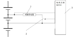
Present stage, electric automobile and the multiplex battery pack of other energy-storage units in order to reduce in actual applications issuable inconsistence problems of battery pack, need the special equalizing circuit of design, and each battery core in the battery pack is carried out online equilibrium.Consider cost, complexity and the reliability of balancer, generally balancer is carried out Integrated design with battery management system, make battery management system possess passive equalization function, simultaneously, also have equalizing circuit is independently become balancer.Accompanying drawing 1 is existing a kind of equalizing circuit principle schematic, this circuit comprises the collection line that is connected in each battery cell two ends, gathering line is connected with control chip with detection and is connected, between each battery cell positive pole and negative pole, be in series with equalizing resistance 1 and equalizer switch 2, this equalizer switch is by detecting and control chip 3 controls, when existing between two battery cells when unbalanced, detects and the conducting of control chip control equalizer switch, consume energy consumption by equalizing resistance, make two battery cells for consistent.
Because equalizing circuit and balancer are realized equilibrium in the mode that adopts the energy consumption formula, if euqalizing current is out of control, or the electronic devices and components of equalizing circuit appearance inefficacy, the equalizing circuit continuous firing caused, will there be the possibility that causes battery cell to be crossed putting, and then might produces safety problem.
Existing product did not possess when equalizing circuit occur to lose efficacy, and prevented that battery from crossing the function of putting, and can make battery cell occur putting, and caused the battery cell damage, produced serious economic loss and safety problem.
The utility model content
In view of this, the technical problems to be solved in the utility model provides the passive equalizing circuit potential failure safety protection circuit that a kind of cost is low, can effectively prevent from damaging in the situation that equalizing circuit lost efficacy battery cell.
In order to solve the problems of the technologies described above, this technical problem adopts following solution:
A kind of passive equalizing circuit potential failure safety protection circuit, being connected in battery cell positive pole and negative pole gathers between the line, comprise the pressure limiting resistance that is series at successively between battery cell positive pole and the negative pole, divider resistance R1, divider resistance R2 and equalizer switch, this equalizer switch is connected with detection and control chip, between pressure limiting resistance and equalizer switch, be connected with and divider resistance R1, the voltage-stabiliser tube of divider resistance R2 parallel connection, the incoming end of this voltage-stabiliser tube is connected with equalizer switch, picking out end is connected with pressure limiting resistance, reference edge is connected between divider resistance R1 and the divider resistance R2.
Compared with prior art, the utility model is by the hardware designs means, solve the potential impact that battery equalizing circuit lost efficacy and produces, for different battery core demands, can adjust very flexibly the application demand that the divider resistance parameter can adapt to different battery cores, adopt cost effective method, the battery that effectively by the Passive components realization battery was caused because equalizing circuit lost efficacy is crossed and is put danger, eliminates safe hidden trouble.
Description of drawings
Fig. 1 is existing a kind of equalizing circuit principle schematic.
Fig. 2 is the utility model embodiment circuit theory schematic diagram.
Embodiment
For the ease of it will be appreciated by those skilled in the art that below in conjunction with embodiment the utility model is described in further detail:
The passive equalizing circuit potential failure safety protection circuit that present embodiment discloses mainly solves electric automobile or other adopts in the occasion of more piece chemical cell as energy-storage system, when adopting the energy consumption mode that each battery cell is carried out passive equilibrium, equalizing circuit occur to lose efficacy and not controlled, cause existing battery cell is crossed the possibility of putting, even have safety issue.By the scheme that present embodiment proposes, in the time of can effectively being limited in equalizing circuit appearance inefficacy, and do not make battery cell occur putting, cause battery cell to damage, prevent the generation of cell safety accident.
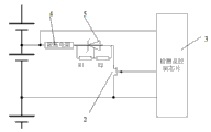
In detail as shown in Figure 2.This passive equalizing circuit potential failure safety protection circuit is connected in the battery cell positive pole and negative pole gathers between the line, comprise the pressure limiting resistance 4 that is series at successively between battery cell positive pole and the negative pole, divider resistance R1, divider resistance R2 and equalizer switch 2, this equalizer switch 2 is connected with detection and control chip 3, between pressure limiting resistance 4 and equalizer switch 2, be connected with and divider resistance R1, the voltage-stabiliser tube 5 of divider resistance R2 parallel connection, the incoming end of this voltage-stabiliser tube 5 is connected with equalizer switch 2, picking out end is connected with pressure limiting resistance 4, reference edge is connected between divider resistance R1 and the divider resistance R2, divider resistance R2 parallel connection can be used for regulating the voltage stabilizing value at voltage-stabiliser tube 5 two ends, and the adjustable voltage-stabiliser tube of 2.5V is adopted in this programme design.
The utility model passes through hardware measure; solve the problem that battery is put because equalizing circuit appearance inefficacy causes battery cell to be crossed; this circuit class is by flexible choice configure hardware parameter; the demand that adapts to the different chemical battery protection can adapt to the practical application needs of the multiple battery such as lead-acid battery, ferric phosphate lithium cell, lithium manganate battery, lithium titanate battery.
Press the demand of protection point for the safe overdischarge that adapts to ferric phosphate lithium cell, be typically designed to 10% point of battery rated capacity, corresponding magnitude of voltage is about 3.1V.According to this demand, the ratio of divider resistance R1 and divider resistance R2 can be set as 6:25.And then when losing efficacy appears in equalizing circuit, equalizing circuit will continue battery cell is discharged, when battery cell voltage reaches 3.1V when following, euqalizing current will be subject to the restriction of voltage-stabiliser tube and balanced current reduction is arrived about about 0A, thereby guarantee the use procedure in later stage, the inefficacy of equalizing circuit can further not cause battery cell to occur putting.If in order to adapt to the demand of lithium manganate battery, the magnitude of voltage of 10% correspondence of battery rated capacity is about 3.65V.Equally, according to this demand, the proportionate relationship of divider resistance R1 and divider resistance R2 can be set as 16:21.
Equally; if in order to adapt to the lower lithium titanate battery of voltage platform; then the selection of voltage-stabiliser tube is adjusted into the pressurizer of 1.2V, parameter divider resistance R1 and divider resistance R2 adopt similar method for designing, can realize the mistake of lithium titanate battery is put safeguard protection.
Above-described embodiment only is wherein specific implementation of the present utility model, and it describes comparatively concrete and detailed, but can not therefore be interpreted as the restriction to the utility model claim.Should be pointed out that for the person of ordinary skill of the art, without departing from the concept of the premise utility, can also make some distortion and improvement, these apparent replacement forms all belong to protection range of the present utility model.
Claims (1)
1. passive equalizing circuit potential failure safety protection circuit, being connected in battery cell positive pole and negative pole gathers between the line, it is characterized in that, comprise the pressure limiting resistance (4) that is series at successively between battery cell positive pole and the negative pole, divider resistance R1, divider resistance R2 and equalizer switch (2), this equalizer switch is connected with detection and control chip (3), between pressure limiting resistance and equalizer switch, be connected with and divider resistance R1, the voltage-stabiliser tube (5) of divider resistance R2 parallel connection, the incoming end of this voltage-stabiliser tube is connected with equalizer switch, picking out end is connected with pressure limiting resistance, reference edge is connected between divider resistance R1 and the divider resistance R2.
Priority Applications (1)
| Application Number | Priority Date | Filing Date | Title |
|---|---|---|---|
| CN 201220440623 CN202797907U (en) | 2012-08-31 | 2012-08-31 | Potential failure safety protection circuit of passive equalization circuit |
Applications Claiming Priority (1)
| Application Number | Priority Date | Filing Date | Title |
|---|---|---|---|
| CN 201220440623 CN202797907U (en) | 2012-08-31 | 2012-08-31 | Potential failure safety protection circuit of passive equalization circuit |
Publications (1)
| Publication Number | Publication Date |
|---|---|
| CN202797907U true CN202797907U (en) | 2013-03-13 |
Family
ID=47825085
Family Applications (1)
| Application Number | Title | Priority Date | Filing Date |
|---|---|---|---|
| CN 201220440623 Expired - Fee Related CN202797907U (en) | 2012-08-31 | 2012-08-31 | Potential failure safety protection circuit of passive equalization circuit |
Country Status (1)
| Country | Link |
|---|---|
| CN (1) | CN202797907U (en) |
Cited By (3)
| Publication number | Priority date | Publication date | Assignee | Title |
|---|---|---|---|---|
| CN105098933A (en) * | 2015-09-28 | 2015-11-25 | 重庆长安汽车股份有限公司 | Battery monomer acquisition detection device |
| CN106240391A (en) * | 2016-08-15 | 2016-12-21 | 惠州市蓝微新源技术有限公司 | A kind of passive equalizing circuit of battery management system |
| CN108226791A (en) * | 2017-11-30 | 2018-06-29 | 宁德时代新能源科技股份有限公司 | Passive equalization circuit detection device and method, battery pack and battery management system |
-
2012
- 2012-08-31 CN CN 201220440623 patent/CN202797907U/en not_active Expired - Fee Related
Cited By (3)
| Publication number | Priority date | Publication date | Assignee | Title |
|---|---|---|---|---|
| CN105098933A (en) * | 2015-09-28 | 2015-11-25 | 重庆长安汽车股份有限公司 | Battery monomer acquisition detection device |
| CN106240391A (en) * | 2016-08-15 | 2016-12-21 | 惠州市蓝微新源技术有限公司 | A kind of passive equalizing circuit of battery management system |
| CN108226791A (en) * | 2017-11-30 | 2018-06-29 | 宁德时代新能源科技股份有限公司 | Passive equalization circuit detection device and method, battery pack and battery management system |
Similar Documents
| Publication | Publication Date | Title |
|---|---|---|
| CN201699585U (en) | Novel intelligent voltage stabilizing circuit | |
| CN102208823B (en) | Uninterrupted power system used for automatic ticket checker | |
| CN202794479U (en) | Failure on-line detection circuit of passive equalization circuit | |
| CN104201654A (en) | Battery pack balance protecting system and method | |
| CN104064827A (en) | Nickel-metal hydride battery pack with safety protection system | |
| CN204407963U (en) | A kind of lithium battery administration module possessing multifunction protection and electric quantity monitoring | |
| CN202014087U (en) | Lithium battery charging protection circuit for portable system | |
| CN104734260A (en) | Power battery equalizing charge method and system | |
| CN202616757U (en) | Protective device of lithium-ion battery pack | |
| CN202797907U (en) | Potential failure safety protection circuit of passive equalization circuit | |
| TWI610486B (en) | Active balance charging device | |
| CN202794448U (en) | Failure on-line detection hardware feedback circuit of passive equalization circuit | |
| CN204758746U (en) | Do benefit to and judge that electricity adds circuit of electrothermal relay adhesion | |
| CN202374006U (en) | Lithium ion battery charging power supply with activation function | |
| CN203456930U (en) | Compound energy system | |
| TWM518824U (en) | Charging device with active charge equalization | |
| CN108128173A (en) | For the protection circuit of super capacitor module | |
| CN204012756U (en) | Dynamic lithium battery group administrative protection device | |
| CN102957175B (en) | Multi-cell serially-connected lithium battery pack equalization and protection system | |
| CN203747460U (en) | Novel lithium battery BMS power supply system | |
| TW201724635A (en) | Active balanced charging device for achieving charging balance among multiple battery modules of secondary battery | |
| CN203352148U (en) | Lithium battery protection system | |
| CN202260560U (en) | Machine-mounted lithium battery charger | |
| CN203135471U (en) | Cell control system and cell control and management system | |
| CN208190281U (en) | A kind of external passive balancer |
Legal Events
| Date | Code | Title | Description |
|---|---|---|---|
| C14 | Grant of patent or utility model | ||
| GR01 | Patent grant | ||
| CF01 | Termination of patent right due to non-payment of annual fee | ||
| CF01 | Termination of patent right due to non-payment of annual fee |
Granted publication date: 20130313 Termination date: 20190831 |