CN202783931U - Case feeding device used in combination with full-automatic case packer - Google Patents
Case feeding device used in combination with full-automatic case packer Download PDFInfo
- Publication number
- CN202783931U CN202783931U CN 201220440126 CN201220440126U CN202783931U CN 202783931 U CN202783931 U CN 202783931U CN 201220440126 CN201220440126 CN 201220440126 CN 201220440126 U CN201220440126 U CN 201220440126U CN 202783931 U CN202783931 U CN 202783931U
- Authority
- CN
- China
- Prior art keywords
- travel
- ing rest
- full
- fixed support
- filling machine
- Prior art date
- Legal status (The legal status is an assumption and is not a legal conclusion. Google has not performed a legal analysis and makes no representation as to the accuracy of the status listed.)
- Withdrawn - After Issue
Links
Images


Abstract
The utility model discloses a case feeding device used in combination with a full-automatic case packer. The case feeding device comprises a fixed support and a movable support. The movable support and the fixed support are fixed to each other through a positioning and locking mechanism, two front baffles are symmetrically arranged on the left and the right sides of the front end of the fixed support respectively, an up-pushing mechanism is arranged at the top of the fixed support and can push nylon delivery cases, and front guide rods are positioned at the lower part of the fixed support and is tilted downwards from the rear end to the front end of each front guide rod; a plurality of rear guide rods are arranged in the movable support and tilted downwards from the rear end to the front end of each rear guide rod; all the front guide rods and all the rear guide rods form a delivery plane which is tilted downwards from the rear end to the front end; a down-pushing mechanism is arranged in the movable support and can push nylon delivery cases; and two rear baffles are arranged on the left and the right sides of the front end of the movable support respectively; and a moving mechanism is arranged at the bottom of the movable support and can move the movable support. The case feeding device has the advantages of high work efficiency and capability of continuously feeding nylon delivery cases.
Description
Technical field
The utility model relates to the package packing machine field, is specifically related to the casing feeding unit supporting with the Full-automatic box filling machine of packing strip or box-like article.
Background technology
Present stage, people are to strip or box-like article---when loading and transporting such as the bar cigarette, the general PE film thermal contraction machine that adopts is finished packing work: use first the PE film that stacked good article are wrapped up, then heat the PE film and make it be subjected to thermal contraction to be attached at article surface, so just finished the packing to stacked good article; But the shortcoming of this manner of packing is: on the one hand, the PE film is difficult to direct repeat to be used, and on the other hand, the PE film can volatilize the toxic substance that is unfavorable for health when high temperature, for hidden danger has been buried in workman's safety in production.At present, people have produced a kind ofly can repeat to reclaim use, safety non-toxic, can load and transport, have the nylon material distribution box of electronic barcode to strip or box-like article, and produced can be to automatically the unpack Full-automatic box filling machine of joint sealing operation of nylon distribution box.Present stage adopts integral type casing feeding unit to match with Full-automatic box filling machine, to close up into by integral type casing feeding unit in the nylon distribution box feeding Full-automatic box filling machine of flats and vertically discharging, but this integral type casing feeding unit can not be realized the continuously uninterrupted feeding to casing, and work efficiency is not high.
The utility model content
The purpose of this utility model provide a kind of can realize with the nylon distribution box continuously uninterrupted feeding with the supporting casing feeding unit of Full-automatic box filling machine.
For achieving the above object, the utility model has adopted following technical scheme: the casing feeding unit that described and Full-automatic box filling machine is supporting comprises: fixed support and travel(l)ing rest, and travel(l)ing rest and fixed support can interfix by location locking mechanism; Be symmetrically arranged with respectively a front baffle board in support bracket fastened front end arranged on left and right sides, be provided with at support bracket fastened top and can push the upper pushing mechanism that the nylon distribution box moves along front guide rod, described front guide rod is positioned at fixed support bottom and the gradually downward-sloping setting of its rear end forward end; Be provided with some from rear end forward end downward-sloping back-guiding rod gradually in the travel(l)ing rest, described before all guide rods and all back-guiding rods can jointly form from rear end forward end downward-sloping transporting flat gradually, in travel(l)ing rest, be provided with and promote the push-down machine structure that the nylon distribution box moves along back-guiding rod, be movably set with a rear plate washer that can horizontally slip in that travel(l)ing rest front end arranged on left and right sides is symmetrical respectively, also be provided with in the travel(l)ing rest bottom can mobile travel(l)ing rest travel mechanism.
Further, the casing feeding unit that aforesaid and Full-automatic box filling machine is supporting, wherein: the structure of described location locking mechanism is: the arranged on left and right sides in the fixed support rear end is hinged with respectively a positioning plate, positioning plate one end is provided with spacing bayonet socket, arranged on left and right sides at the travel(l)ing rest front end is separately installed with a locating dowel pin, the rotary spacing plate can be locked in locating dowel pin in the spacing bayonet socket.
Further, the casing feeding unit that aforesaid and Full-automatic box filling machine is supporting, wherein: the structure of described upper pushing mechanism is: the acclivitous front slide bar in outer end is installed at support bracket fastened top, be provided with the top shoe that can move and rotate along front slide bar on the front slide bar, the top shoe bottom is equipped with a upper push pedal.
Further, the casing feeding unit that aforesaid and Full-automatic box filling machine is supporting, wherein: the structure of described push-down machine structure is: have some from its rear end forward end downward-sloping drop shot gradually at the travel(l)ing rest internal support, be provided with the sliding block that can move along drop shot on the drop shot, the sliding block top is equipped with a lower push pedal.
Further, the casing feeding unit that aforesaid and Full-automatic box filling machine is supporting, wherein: the structure of described travel mechanism is: the some rollers that are installed on the travel(l)ing rest bottom.
Further, the casing feeding unit that aforesaid and Full-automatic box filling machine is supporting, wherein: also be provided with introducing mechanism at the fixed support afterbody, introducing mechanism comprises and is up and down symmetrically arranged upper importing plate and lower importing plate that the outer end of described upper importing plate, lower importing plate is respectively along the outside flare up of its vertical direction " eight " font; Be provided with the position-limited lever that can embed between importing plate and the lower importing plate in the front portion of travel(l)ing rest.
By the enforcement of technique scheme, the utlity model has high efficiency, can realize the continuously advantage of uninterrupted feeding with the nylon distribution box.
Description of drawings
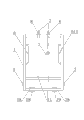
Fig. 1 is the structural representation of the supporting casing feeding unit of described in the utility model and Full-automatic box filling machine.
Fig. 2 is the structural representation of overlooking direction of Fig. 1.
Fig. 3 is the rear plate washer shown in the right apparent direction of Fig. 1, locating dowel pin, position-limited lever three's positional structure scheme drawing.
Fig. 4 is the positional structure scheme drawing of the fixed support shown in the right apparent direction of Fig. 1, front baffle board, positioning plate, introducing mechanism, upper pushing mechanism.
The specific embodiment
The utility model is described in further detail below in conjunction with the drawings and specific embodiments.
Such as Fig. 1, Fig. 2, Fig. 3, shown in Figure 4, the casing feeding unit that described and Full-automatic box filling machine is supporting: comprising: fixed support 1 and travel(l)ing rest 2, travel(l)ing rest 2 and fixed support 1 interfix by location locking mechanism, in the present embodiment, the structure of described location locking mechanism is: the left side in fixed support 1 rear end, right both sides are hinged with respectively a positioning plate 3, one end of positioning plate 3 is provided with spacing bayonet socket 4, left side at travel(l)ing rest 2 front ends, right both sides are separately installed with a locating dowel pin 5, rotary spacing plate 3 can be locked in locating dowel pin 5 in the spacing bayonet socket 4; Left side at fixed support 1 front end is provided with front baffle board 6, the right side is provided with front baffle board 611, front baffle board 6,611 is and is symmetrical arranged, be provided with at the top of fixed support 1 and can push the upper pushing mechanism that the nylon distribution box moves forward along front guide rod 11, described front guide rod 11 be positioned at fixed support 1 bottom and its rear end forward end downward-sloping gradually; In the present embodiment, the structure of upper pushing mechanism is: the acclivitous front slide bar 7 in outer end is installed at the top of fixed support 1, is provided with the top shoe 8 that can move and rotate along front slide bar 7 on the front slide bar 7, top shoe 8 bottoms are equipped with a upper push pedal 9; Be provided with some from rear end forward end downward-sloping back-guiding rod 12 gradually in the travel(l)ing rest 2, described before all guide rods 11 and all back-guiding rods 12 can jointly form from rear end forward end downward-sloping transporting flat gradually, in travel(l)ing rest 2, be provided with and promote the push-down machine structure that the nylon distribution box moves forward along back-guiding rod 12, in the present embodiment, the structure of described push-down machine structure is: have from rear end forward end downward-sloping drop shot 13 gradually at travel(l)ing rest 2 internal supports, be provided with the sliding block 14 that can move along drop shot 13 on the drop shot 13, sliding block 14 tops are equipped with a lower push pedal 15; Be movably set with the rear plate washer 16 that can horizontally slip, a front end right side in travel(l)ing rest 2 front ends left sides and be movably set with a rear plate washer 161 that can horizontally slip, rear plate washer 16,161 is and is symmetrical arranged; Also be provided with in the bottom of travel(l)ing rest 2 can mobile travel(l)ing rest 2 travel mechanism, in the present embodiment, the structure of travel mechanism is: the roller 17 that is installed on travel(l)ing rest 2 bottoms.More easily mobile travel(l)ing rest 2 is set behind the roller 17, can loads more easily the nylon distribution box; In the present embodiment, also be provided with introducing mechanism at fixed support 1 afterbody, described introducing mechanism comprises and is up and down symmetrically arranged upper importing plate 18 and lower importing plate 19 that the outer end of described upper importing plate 18, lower importing plate 19 is respectively along the outside flare up of its vertical direction " eight " font; Be provided with the position-limited lever 20 that can embed between importing plate 18 and the lower importing plate 19 in the front portion of travel(l)ing rest 2.In practical application, the casing of fixed support 1 front end and Full-automatic box filling machine 10 feeding end fixes.
Principle of work of the present utility model is as follows: at first the rear plate washer 16 in the travel(l)ing rest 2,161 is pushed respectively to the inside, formation is in order to the shelves face against the nylon distribution box, the nylon distribution box that then will vertically discharge places on the back-guiding rod 12, push pedal 15 was moved along drop shot 13 under sliding block 14 drove under Action of Gravity Field, until prop up the nylon distribution box; Follow mobile travel(l)ing rest 2, the position-limited lever 20 at its front end is embedded between the upper importing plate 18 and lower importing plate 19 of fixed support 1 afterbody, can position travel(l)ing rest 2 easily like this; Then the rotary spacing plate 3, and spacing bayonet socket 4 is blocked locating dowel pin 5, finish captiveing joint of fixed support 1 and travel(l)ing rest 2; The upper push pedal 9 that will be positioned on the fixed support 1 at this moment, turns to its top along front slide bar 7; Then rear plate washer 16,161 is pulled open laterally, the nylon distribution box is entered in the fixed support 1 along front guide rod 11 under the pushing of lower push pedal 15, until the nylon distribution box is resisted against on front baffle board 6,611 block faces that form; Because the feeding of the casing in the Full-automatic box filling machine 10 end is provided with and can adsorbs the feeder of sending operation to flats nylon distribution box, feeder can make the generation deformation of nylon distribution box and enter in the Full-automatic box filling machine 10 along front baffle board 6,611 inboard, along with the nylon distribution box constantly feeds in the Full-automatic box filling machine 10, when the quantity of nylon distribution box is reduced to when only being positioned at fixed support 1 scope, push pedal is located at the below of front slide bar 7 in the rotation, goes up like this push pedal 9 and just can compress along 7 pairs of nylon distribution boxes of front slide bar; At this moment, can rotary spacing plate 3, positioning plate 3 and locating dowel pin 5 are thrown off mutually, at this moment travel(l)ing rest 2 can break away from fixed support 1, follows travel(l)ing rest 2 is pushed into nylon distribution box loading area carries out loading to the nylon distribution box; Repeat aforesaid operations, namely can realize the continuously uninterrupted feeding to the nylon distribution box.The utlity model has high efficiency, can realize the continuously advantage of uninterrupted feeding with the nylon distribution box.
Claims (6)
1. with the supporting casing feeding unit of Full-automatic box filling machine, it is characterized in that: comprising: fixed support and travel(l)ing rest, travel(l)ing rest and fixed support can interfix by location locking mechanism; Be symmetrically arranged with respectively a front baffle board in support bracket fastened front end arranged on left and right sides, be provided with at support bracket fastened top and can push the upper pushing mechanism that the nylon distribution box moves along front guide rod, described front guide rod is positioned at fixed support bottom and the gradually downward-sloping setting of its rear end forward end; Be provided with some from rear end forward end downward-sloping back-guiding rod gradually in the travel(l)ing rest, described before all guide rods and all back-guiding rods can jointly form from rear end forward end downward-sloping transporting flat gradually, in travel(l)ing rest, be provided with and promote the push-down machine structure that the nylon distribution box moves along back-guiding rod, be movably set with a rear plate washer that can horizontally slip in that travel(l)ing rest front end arranged on left and right sides is symmetrical respectively, also be provided with in the travel(l)ing rest bottom can mobile travel(l)ing rest travel mechanism.
2. the supporting casing feeding unit of according to claim 1 and Full-automatic box filling machine, it is characterized in that: the structure of described location locking mechanism is: the arranged on left and right sides in the fixed support rear end is hinged with respectively a positioning plate, positioning plate one end is provided with spacing bayonet socket, arranged on left and right sides at the travel(l)ing rest front end is separately installed with a locating dowel pin, the rotary spacing plate can be locked in locating dowel pin in the spacing bayonet socket.
3. the supporting casing feeding unit of according to claim 1 and 2 and Full-automatic box filling machine, it is characterized in that: the structure of described upper pushing mechanism is: the acclivitous front slide bar in outer end is installed at support bracket fastened top, be provided with the top shoe that can move and rotate along front slide bar on the front slide bar, the top shoe bottom is equipped with a upper push pedal.
4. the supporting casing feeding unit of according to claim 1 and 2 and Full-automatic box filling machine, it is characterized in that: the structure of described push-down machine structure is: have some from its rear end forward end downward-sloping drop shot gradually at the travel(l)ing rest internal support, be provided with the sliding block that can move along drop shot on the drop shot, the sliding block top is equipped with a lower push pedal.
5. the supporting casing feeding unit of according to claim 1 and Full-automatic box filling machine, it is characterized in that: the structure of described travel mechanism is: the some rollers that are installed on the travel(l)ing rest bottom.
6. the supporting casing feeding unit of according to claim 1 and 2 and Full-automatic box filling machine, it is characterized in that: also be provided with introducing mechanism at the fixed support afterbody, introducing mechanism comprises and is up and down symmetrically arranged upper importing plate and lower importing plate that the outer end of described upper importing plate, lower importing plate is respectively along the outside flare up of its vertical direction " eight " font; Be provided with the position-limited lever that can embed between importing plate and the lower importing plate in the front portion of travel(l)ing rest.
Priority Applications (1)
| Application Number | Priority Date | Filing Date | Title |
|---|---|---|---|
| CN 201220440126 CN202783931U (en) | 2012-08-31 | 2012-08-31 | Case feeding device used in combination with full-automatic case packer |
Applications Claiming Priority (1)
| Application Number | Priority Date | Filing Date | Title |
|---|---|---|---|
| CN 201220440126 CN202783931U (en) | 2012-08-31 | 2012-08-31 | Case feeding device used in combination with full-automatic case packer |
Publications (1)
| Publication Number | Publication Date |
|---|---|
| CN202783931U true CN202783931U (en) | 2013-03-13 |
Family
ID=47811246
Family Applications (1)
| Application Number | Title | Priority Date | Filing Date |
|---|---|---|---|
| CN 201220440126 Withdrawn - After Issue CN202783931U (en) | 2012-08-31 | 2012-08-31 | Case feeding device used in combination with full-automatic case packer |
Country Status (1)
| Country | Link |
|---|---|
| CN (1) | CN202783931U (en) |
Cited By (2)
| Publication number | Priority date | Publication date | Assignee | Title |
|---|---|---|---|---|
| CN102849270A (en) * | 2012-08-31 | 2013-01-02 | 张家港市德顺机械有限责任公司 | Box body feeding device matched with full automatic box loader |
| CN103171794A (en) * | 2013-04-09 | 2013-06-26 | 张家港市德顺机械有限责任公司 | Automatic feeding device in full-automatic stacking container loader |
-
2012
- 2012-08-31 CN CN 201220440126 patent/CN202783931U/en not_active Withdrawn - After Issue
Cited By (2)
| Publication number | Priority date | Publication date | Assignee | Title |
|---|---|---|---|---|
| CN102849270A (en) * | 2012-08-31 | 2013-01-02 | 张家港市德顺机械有限责任公司 | Box body feeding device matched with full automatic box loader |
| CN103171794A (en) * | 2013-04-09 | 2013-06-26 | 张家港市德顺机械有限责任公司 | Automatic feeding device in full-automatic stacking container loader |
Similar Documents
| Publication | Publication Date | Title |
|---|---|---|
| CN104058128B (en) | A kind of box packing machine | |
| CN206108446U (en) | Automatic chartered plane is folded in loading | |
| CN207172864U (en) | Rectilinear reason bag machine | |
| CN204660055U (en) | Particle bag packing automatic box packing device | |
| CN202783931U (en) | Case feeding device used in combination with full-automatic case packer | |
| CN204916303U (en) | Automatic box machine of rolling over with vanning device | |
| CN107310772A (en) | One kind divides equally recrater | |
| CN202783925U (en) | Box body opening and positioning device in full-automatic box filling machine | |
| CN208485319U (en) | A kind of electrothermal tube feeding device | |
| CN103010518B (en) | Feeding device for paper and plastic packaging machine | |
| CN206375045U (en) | A kind of corner protector machine | |
| CN102849265A (en) | Supporting and locating device for upper and lower cover plates at rear end of box body in fully automatic box filler | |
| CN102849270B (en) | Box body feeding device matched with full automatic box loader | |
| CN103171794A (en) | Automatic feeding device in full-automatic stacking container loader | |
| CN109305400B (en) | Hydraulic film packaging machine for packaging powder charging plates | |
| CN103204268B (en) | Circulating box opening and conveying device of full-automatic stacking and box filling machine | |
| CN202678466U (en) | Battery tray filler | |
| CN205440928U (en) | Staple packaging machine | |
| CN203199250U (en) | Automatic feeding device in full-automatic stacking-casing machine | |
| CN205855456U (en) | A kind of loading apparatus of bagged material | |
| CN106742196A (en) | A kind of ceramic tile packaging equipment | |
| CN106044282A (en) | Truck loading device of bagged materials | |
| CN202783977U (en) | Box body front-path conveying device in full-automatic box filling machine | |
| CN202783922U (en) | Supporting and positioning device for upper and lower box-body rear-end cover plates in full-automatic box filling machine | |
| CN207209467U (en) | A kind of automatic loading mechanism |
Legal Events
| Date | Code | Title | Description |
|---|---|---|---|
| C14 | Grant of patent or utility model | ||
| GR01 | Patent grant | ||
| AV01 | Patent right actively abandoned |
Granted publication date: 20130313 Effective date of abandoning: 20140709 |
|
| RGAV | Abandon patent right to avoid regrant |