CN202763112U - Drilling device for concentric polycyclic evenly distributed holes - Google Patents
Drilling device for concentric polycyclic evenly distributed holes Download PDFInfo
- Publication number
- CN202763112U CN202763112U CN 201220481556 CN201220481556U CN202763112U CN 202763112 U CN202763112 U CN 202763112U CN 201220481556 CN201220481556 CN 201220481556 CN 201220481556 U CN201220481556 U CN 201220481556U CN 202763112 U CN202763112 U CN 202763112U
- Authority
- CN
- China
- Prior art keywords
- drilling
- gerotor motor
- flange
- brill
- auger spindle
- Prior art date
- Legal status (The legal status is an assumption and is not a legal conclusion. Google has not performed a legal analysis and makes no representation as to the accuracy of the status listed.)
- Expired - Fee Related
Links
Images


Abstract
The utility model discloses a drilling device for concentric polycyclic evenly distributed holes and belongs to the technical field of machining. The drilling device for the concentric polycyclic evenly distributed holes comprises a rocker arm drilling machine, wherein a vertical guide mechanism is arranged below a main shaft box of the rocker arm drilling machine, an electromagnetism indexing mechanism is connected below the guide mechanism, a drilling disc used for adjusting a radial position of a drill is connected below the electromagnetism indexing mechanism, and a drill spindle mechanism is installed below the drilling disc mechanism. The drill spindle mechanism comprises a middle shaft and a plurality of output shafts, wherein the middle shaft is driven by a hydraulic device, located in the middle of the drilling disc mechanism and used for installing of the middle shaft, and the plurality of the output shafts are evenly distributed below the drilling disc mechanism and used for installing of the drill. A drilling machine main shaft of the rocker arm drilling machine is in connection with the guide mechanism and the hydraulic device used for driving the drill spindle mechanism through an output shaft. According to the drilling device for the concentric polycyclic evenly distributed holes, not only can the simultaneous drilling of polycyclic holes of parts in large sizes be achieved through one clamping, but also positional accuracy and dimensional accuracy of the parts can be improved due to the arrangement of the Archimedes spiral mechanism.
Description
Technical field
The utility model relates to the Machining Technology field, specifically a kind of mechanical devices that encircle with one heart uniform porose disc class part for drilling processing more.
Background technology
At present, in the production of machine components, the processing of periphery hole is generally carried out drilling processing with common driller; and the position in hole need to be determined by modes such as line, use drill jig or numerical control programming point nests; so that process route is longer, affects manufacturing schedule, and production cost increases.In addition, common driller once can only hole of drilling, to the processing of porous part, need to machine a hole after, reprocess another hole, efficient is very low.Especially with one heart encircle uniform porose disc class part more, not only the quantity in hole is many, and each hole there is higher position degree requirement, even, also have the mutual alignment requirement between the uniform hole on the same workpiece different rings and between the uniform hole on the different workpieces, adopt common driller processing, not only working (machining) efficiency is too low, and since repeatedly drilling cause scale error and position error all too large so that assembling difficulty between each workpiece, the needs that can not satisfy productions, assemble.
Once can only process a hole, problem that efficient is too low for solving common driller, but Chinese patent CN201350514Y discloses the drilling machine that a kind of porous is processed simultaneously, comprise support body, electric machine main shaft, transfer panel, driving shaft, driven shaft, driving gear, driven gear, drill bit, anchor clamps, it is characterized in that driving shaft drives simultaneously four driven shafts and rotates, electric machine main shaft drives four drill bits and works simultaneously, is a kind of multi-pore drilling machine that can process simultaneously four holes.Efficient has been improved in four holes of this drilling machine time processing, determines but bit location is Machine Tool design, and the radial position of drill bit is non-adjustable, can only process certain specific component, does not have versatility.
Also have some Multi-hole drilling devices mostly take upright drill as parent, drill press spindle drives isolated plant and the bit processing porous part of designed, designed, and this device is subject to the restriction of the range of work of lathe own, can't realize the processing to large-size workpiece.
The utility model content
The utility model technical issues that need to address provide a kind of uniform hole drilling device of with one heart many rings that can realize by clamped one time the simultaneously drilling of porous of part, and positional precision and the dimensional accuracy of on this basis raising boring.
For solving the problems of the technologies described above, the technical scheme that the utility model adopts is:
The uniform hole drilling device of a kind of with one heart many rings, comprise radial drilling machine, be provided with vertical guiding mechanism below the main spindle box of described radial drilling machine, the following connection Electro-magnetic Graduation mechanism of guiding mechanism, the following connection of Electro-magnetic Graduation mechanism is used for adjusting the brill disc mechanism of drill bit radial position, bore and auger spindle mechanism to be installed below the disc mechanism, described auger spindle mechanism comprises that boring the disc mechanism center by being positioned at of driving of hydraulic means is used for the jackshaft of mounting center axle and is distributed on boring a plurality of output shafts that are used for installing drill bit below the disc mechanism; The machine tool chief axis of described radial drilling machine is by the hydraulic means of power shaft difference connection guiding mechanism and driving auger spindle mechanism.
Further improvement of the utility model is: described guiding mechanism comprises the outer guide sleeve that is fixedly installed on below the main spindle box, arrange in the outer guide sleeve one by the key piece spacing and with the inner sleeve of outer guide sleeve axial sliding fit, one end of described power shaft is connected on the machine tool chief axis, and described inner sleeve is arranged on the power shaft by two groups of bearing A.
Further improvement of the utility model is: described Electro-magnetic Graduation mechanism comprises the index dial that is used for rotary index that is sleeved on the power shaft outside, the electromagnet of straining or unclamping index dial is installed in the inner sleeve of guiding mechanism, is carved with the graduation mark for calibration on the excircle of described inner sleeve.
Further improvement of the utility model is: described brill disc mechanism comprises the brill dish that is fixedly connected on below the index dial, is provided with a pair of intermeshing crossed axis angle in the brill dish and is 90 ° bevel pinion and bevel gear wheel; The afterbody of described bevel pinion is provided with for the cubic hole of inserting spanner; Be provided with spiral of Archimedes below the described bevel gear wheel, the following five equilibrium of brill dish is provided with the radially-directed groove, and the locating piece that is slidingly connected with spiral of Archimedes is set in the described gathering sill; Also be provided with the hydraulic means that drives auger spindle mechanism in the described brill dish, described hydraulic means comprises the two-bit triplet magnetic valve that is connected and rotatablely moving of power shaft changed into hydraulicdriven variable pump and be connected with variable pump with power shaft, and the output of two-bit triplet magnetic valve is connected with auger spindle mechanism.
Further improvement of the utility model is: described auger spindle mechanism comprises being fixedly connected on the gerotor motor A that is communicated with the output two-bit triplet magnetic valve on the locating piece and being fixedly connected on bores the gerotor motor B that disk center is communicated with another output of two-bit triplet magnetic valve, the clutch end of described gerotor motor A is connected with the output shaft that drill bit is installed by coupling band, and the clutch end of described gerotor motor B is connected by the jackshaft of coupling band with the mounting center axle.
Further improvement of the utility model is: be fixedly installed flange cover A below the described gerotor motor A, flange cover A is connected with output shaft by two groups of bearing B, flange overlap be equipped with below the A push down bearing B flange to plate A.
Further improvement of the utility model is: be fixedly installed flange cover B below the described gerotor motor B, flange cover B is connected with jackshaft by two groups of bearing C, flange overlap be equipped with below the B push down bearing C flange to plate B.
Because the technological progress of having adopted technique scheme, the utility model to obtain is:
The uniform hole drilling device of with one heart many rings of the present utility model, take radial drilling machine as parent, guiding mechanism below the main spindle box that is installed in radial drilling machine, Electro-magnetic Graduation mechanism, brill disc mechanism and auger spindle mechanism realize the processing to the uniform hole of the many rings of large scale part.The utility model carries out the centering of part by the central shaft of auger spindle mechanism, removed drilling jig tool from, has reduced line centering operation or numerical control programming point nest centering operation; The mentality of designing of mechanical-electrical-hydraulic integration, and adopt spiral of Archimedes mechanism can clamped one time be processed the uniform hole on the different centre-to-centre spacing, so that the position of holing is more accurate, drilling operation is more convenient; On the brill dish in the utility model different numbers can be set and divide equally groove, with the workpiece of the different hole counts of convenient processing, so that processing practicality of the present utility model, versatility are stronger.
The inner sleeve of guiding mechanism is slidingly matched by key piece and outer guide sleeve, the moving up and down of inner sleeve drive the Electro-magnetic Graduation mechanism be attached thereto, bore disc mechanism and auger spindle mechanism is synchronized with the movement with machine tool chief axis, thereby realize before part is processed in time adjusting according to the length of the height of part and drill bit the purpose of crown height.
The electromagnet of Electro-magnetic Graduation mechanism is installed in the inner sleeve, and the magnetic force that produces after the electromagnet energising can tighten together index dial and inner sleeve with graduation mark; Magnetic force disappears after the electromagnet outage, and index dial and inner sleeve are unclamped, can rotation-indexing table with calibration.
The afterbody that bores the bevel pinion of disc mechanism is provided with cubic hole, can insert spanner and turn bevel pinion, and then rotate bevel gear wheel.Bevel gear wheel drives the locating piece that is attached thereto by following spiral of Archimedes and is installed in auger spindle mechanism on the locating piece, radially-directed groove along the brill dish, equidistant radial moves simultaneously, distance between the drill bit of installing in the adjustment auger spindle mechanism and the machine tool chief axis center line is with the some uniform hole on the drilling workpiece different radii.According to the quantity in uniform hole on the same center circle of workpiece, can make the multiple brill dish with minute radially-directed grooves such as differences, to adapt to the needs of different parts.In addition, the variable pump of brill disc mechanism and two-bit triplet magnetic valve rotatablely moving of machine tool chief axis can be converted to hydraulic drive and a minute multichannel passes to a plurality of drill bits, realizes simultaneously drilling of porous, and production efficiency greatly improves.
The gerotor motor of auger spindle mechanism is reduced into machine driving with the hydraulic drive that the two-bit triplet magnetic valve is divided into multichannel, and exports to a plurality of output shafts with multichannel, and then drives a plurality of drill bits and work simultaneously.Gerotor motor is connected with output shaft by coupling band, and drill bit is installed on the output shaft, can realize drilling, and is positioned at all right mounting center axle on the jackshaft that bores disk center, and magnetic power meter is adsorbed on the central shaft, can realize the centering of workpiece.
Description of drawings
Fig. 1 is general structure schematic diagram of the present utility model;
Fig. 2 is the guiding mechanism structural representation;
Fig. 3 is Electro-magnetic Graduation mechanism structure schematic diagram;
Fig. 4 is for boring the disc mechanism structural representation;
Fig. 5 is the auger spindle mechanism structural representation on the locating piece;
Fig. 6 is for boring the auger spindle mechanism structural representation of disk center;
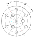
Fig. 7 is the part schematic diagram that the utility model and the course of work process;
Wherein, 1, output shaft, 2-1, gerotor motor A, 2-2, gerotor motor B, 3, bevel pinion, 4, the two-bit triplet magnetic valve, 5, variable pump, 6, inner sleeve, 7, outer guide sleeve, 8, main spindle box, 9, machine tool chief axis, 10, power shaft, 11, electromagnet, 12, index dial, 13, the brill dish, 14, central shaft, 15, bevel gear wheel, 16, drill bit, 17, magnetic power meter, 18, bearing cap A, 19, bearing A, 20, the key piece, 21, locating piece, 22, bearing B, 23-1, flange cover A, 23-2, flange cover B, 24-1, flange is to plate A, 24-2, flange is to plate B, 25, jackshaft, 26, bearing C.
The specific embodiment
Below in conjunction with accompanying drawing the utility model is described in further details:
As shown in Figure 1, the uniform hole drilling device of with one heart many rings of the present utility model, be take radial drilling machine as parent, be installed in the additional device for machine tools below the main spindle box 8 of radial drilling machine, this device comprises from guiding mechanism, the Electro-magnetic Graduation mechanism that main spindle box 8 arranges successively downwards, bores disc mechanism, four parts of auger spindle mechanism.
Guiding mechanism is used for connecting this device to radial drilling machine, and device is moved axially.Guiding mechanism vertically be arranged on main spindle box 8 below, comprise power shaft 10, outer guide sleeve 7 and inner sleeve 6, power shaft 10 is connected with machine tool chief axis 9 by Morse's taper, with the transmission of power of lathe to power shaft 10.Outer guide sleeve 7 be fixedly installed on main spindle box 8 below, inner sleeve 6 is arranged in the hole of outer guide sleeve 7, is provided with key piece 20 between outer guide sleeve 7 and the inner sleeve 6, inner sleeve 6 is slidingly matched by key piece 20 and outer guide sleeve 7.Outer guide sleeve 7 and inner sleeve 6 are sleeved on the center with machine tool chief axis 9 and power shaft 10.The blind hole of inner sleeve 6 is interior, the step both sides of power shaft 10 are respectively arranged with upper and lower two groups of bearing A19, and wherein the outside of the bearing A19 of blind hole oral area also is provided with bearing cap A18.When machine tool chief axis 9 band driven input shafts 10 moved axially, inner sleeve 6 endwisely slipped by key piece 20 and outer guide sleeve 7, when processing parts, and can be according to the length of height and the drill bit 16 of workpiece, the height of corresponding adjustment drill bit 16.
Electro-magnetic Graduation mechanism is used for calibration.Electro-magnetic Graduation mechanism be arranged on guiding mechanism below, comprise index dial 12 and electromagnet 11, Electro-magnetic Graduation mechanism is connected with the inner sleeve 6 of guiding mechanism by index dial 12, index dial 12 is arranged on below the inner sleeve 6, corresponding with inner sleeve 6 sizes, index dial 12 is used for the anglec of rotation with calibration, is carved with graduation mark on the excircle of inner sleeve 6, is used to indicate the size of index dial 12 anglecs of rotation.Electromagnet 11 is installed in the inner sleeve 6 of guiding mechanism, is used for tension or unclamps index dial 12, i.e. the magnetic force that produces during electromagnet 11 energising can tighten together index dial 12 and inner sleeve 6; Magnetic force disappears after electromagnet 11 outages, and index dial 12 unclamps with inner sleeve 6, and can realize by rotation-indexing table 12 adjustment of bore position this moment.
Bore disc mechanism and be used for adjusting drill bit 16 radial positions.Bore disc mechanism be arranged on Electro-magnetic Graduation mechanism below, comprise brill dish 13, bevel pinion 3 and bevel gear wheel 15, brill dish 13 is fixedly connected with the index dial 12 of Electro-magnetic Graduation mechanism.Bevel pinion 3 and bevel gear wheel 15 are intermeshing, and crossed axis angle is 90 °, bevel pinion 3 and bevel gear wheel 15 be sleeved on brill dish 13 in, the afterbody of bevel pinion 3 is provided with cubic hole, be used for to insert spanner.Be provided with spiral of Archimedes below the bevel gear wheel 15, the following five equilibrium of brill dish 13 is provided with the radially-directed groove, be provided with locating piece 21 in the radially-directed groove, the upper surface of locating piece 21 also is provided with spiral of Archimedes, and bevel gear wheel 15 meshes by spiral of Archimedes with locating piece 21.When turning bevel pinion 3 with spanner, bevel pinion 3 drives the bevel gear wheel 15 that is engaged with, bevel gear wheel 15 moves by the radially-directed groove while equidistant radial of spiral of Archimedes driving locating piece 21 along brill dish 13, in the time of locating piece 21 equidistant radial move can drive whole auger spindle mechanism simultaneously equidistant radial move, thereby realize that each drill bit 16 holes at the workpiece different radii.In addition, the radially-directed groove quantity of five equilibrium arranges according to the quantity in the uniform hole of workpiece on the utility model brill dish 13, to adapt to the needs of different parts.Be provided with 6 radially-directed grooves on the brill dish 13 of the present embodiment.
Brill coils and also is provided with the hydraulic means that drives auger spindle mechanism in 13 holes, hydraulic means comprises variable pump 5 and two-bit triplet magnetic valve 4, power shaft 10 is connected by the input of shaft coupling with variable pump 5, and the output of variable pump 5 is connected with the input of two-bit triplet magnetic valve 4.Variable pump 5 changes rotatablely moving of power shaft 10 into hydraulic drive, and two-bit triplet magnetic valve 4 is hydraulic pressure oil content two-way output, respectively control centre's axle 14 and be distributed on the rotation of the output shaft 1 below the brill dish 13.
Auger spindle mechanism be installed in bore disc mechanism below.Auger spindle mechanism is arranged to two parts, a part is arranged on the radius of brill dish 13, be used for installing drill bit 16, comprise gerotor motor A2-1 and output shaft 1, gerotor motor A2-1 is fixedly connected on the locating piece 21, the input of gerotor motor A2-1 is connected with an output of the two-bit triplet magnetic valve 4 that bores disc mechanism, and the clutch end of gerotor motor A2-1 is connected with output shaft 1 by coupling band.Another part of auger spindle mechanism is arranged on the center of brill dish 13, be used for mounting center axle 14, comprise gerotor motor B2-2 and jackshaft 25, gerotor motor B2-2 is fixedly connected on the brill dish 13, the input of gerotor motor B2-2 is connected with another output of the two-bit triplet magnetic valve 4 that bores disc mechanism, and the clutch end of gerotor motor B2-2 is connected with jackshaft 25 by coupling band.
Two-bit triplet magnetic valve 4 is controlled respectively two oil circuits by two outputs, output is connected with gerotor motor A2-1 on the locating piece 21, when 4 energising of two-bit triplet magnetic valve, oil circuit is communicated with gerotor motor A2-1 on the locating piece 21,1 rotation of gerotor motor A2-1 driver output axle, with drill bit 16 output shaft 1 of packing into, can realize a plurality of drill bit 16 simultaneously drillings.Another output is connected with the gerotor motor B2-2 that brill coils 13 centers, when 4 outage of two-bit triplet magnetic valve, the gerotor motor B2-2 that oil circuit and brill coil 13 centers is communicated with, gerotor motor B2-2 drives jackshaft 25 rotations that brill coils 13 centers, and jackshaft 25 can mounting center axle 14.Central shaft 14 is used for the centering workpiece, namely when clamping has workpiece on the workbench, magnetic power meter 17 gauge stands are adsorbed on central shaft 14 outer walls, size and location or excircle of workpiece according to the original datum hole of workpiece, adjust magnetic power meter 17 table pole length and angles, the percentage gauge outfit of magnetic power meter 17 is pressed on the inwall or excircle of workpiece of datum hole, rotary middle spindle 14, according to the numerical value that the percentage gauge outfit of magnetic power meter 17 shows, adjust radial drilling machine alignment of shafts line position until the centering workpiece.Jackshaft 25 also can be installed drill bit, is used for the centre bore of drilling workpiece.
One flange cover A23-1 is set below the gerotor motor A2-1, flange cover A23-1 is fixedly connected on the gerotor motor A2-1, and be sleeved on the outside of output shaft 1, flange overlaps in the A23-1 hole, output shaft 1 step both sides arrange respectively two groups of bearing B22, be provided be used to the flange of pushing down bearing B22 plate A24-1 below the flange cover A23-1, flange is fixedly connected with flange cover A23-1 plate A24-1, can realize the axial location of output shaft 1, course feed during with 16 drilling of assurance drill bit.
One flange cover B23-2 is set below the gerotor motor B2-2, flange cover B23-2 is fixedly connected on the gerotor motor B2-2, and be sleeved on the outside of jackshaft 25, flange overlaps in the B23-2 hole, jackshaft 25 step both sides arrange respectively two groups of bearing C26, be provided be used to the flange of pushing down bearing C26 plate B24-2 below the flange cover B23-2, flange is fixedly connected with flange cover B23-2 plate B24-2, can realize the axial location of jackshaft 25.
The course of work of the present utility model is as described below:
The first step: rotate the crossbeam of radial drilling machine, make machine tool chief axis 9 leave workbench, the workpiece that clamping, tightening will be processed.
Second step: start lathe, drill press spindle 9 drives inner sleeve 6 and slides up and down along outer guide sleeve 7, according to the length of workpiece height and drill bit 16, and the height of the how annular uniform hole drilling device of corresponding adjustment the utility model.
The 3rd step: central shaft 14 is installed on the jackshaft 25, and magnetic power meter 17 gauge stands are adsorbed on central shaft 14 outer walls, according to the size and location of workpiece datum hole, and adjustment form pole length and angle, the percentage gauge outfit is pressed on the inwall of datum hole.10 rotations of machine tool chief axis 9 band driven input shafts, power shaft 10 drives variable pump 5 rotations by coupling band, hydraulic oil is by variable pump 5 input two-bit triplet magnetic valves 4, hydraulic oil is from three-way magnetic valve 4 outputs and drive gerotor motor B2-2 rotation, and gerotor motor B2-2 drives central shaft 14 rotations by jackshaft 25.According to the numerical value that magnetic power meter 17 shows, adjust the position of machine tool chief axis 9, with the centering workpiece, then lock the position of machine tool chief axis 9.
The 4th the step: with spanner by cubic hole hand rotation bevel pinion 3, bevel pinion 3 drives bevel gear wheel 15, spiral of Archimedes below the bevel gear wheel 15 just can be controlled each auger spindle mechanism that is installed on the locating piece 21, radially-directed groove while equidistant radial along brill dish 13 moves, adjustment is installed in drill bit 16 in the auger spindle mechanism and the distance between the machine tool chief axis 9, to guarantee the centre-to-centre spacing size in uniform hole on the workpiece.In the present embodiment, be provided with 6 locating pieces 21, be installed in respectively in 6 radially-directed grooves of brill dish 13.When rotating bevel pinion 3,6 locating pieces 21 drive 6 cover auger spindle mechanisms along the radially-directed groove of brill dish 13 simultaneously equidistant radial move, adjust the size of 6 uniform drill bit 16 place center circle diameters.
The 5th step: after adjusting the radial position of drill bit 16,4 energisings of two-bit triplet magnetic valve, the oil circuit commutation, hydraulic oil flows to the gerotor motor A2-1 on each locating piece 21, and gerotor motor A2-1 rotation drives corresponding output shaft 1 rotation.With drill bit 16 output shaft 1 of packing into, can carry out drilling.The present embodiment gets out 6 uniform holes at workpiece.
The 6th step: drilling is complete, and electromagnet 11 outages are loosened index dial 12 by deadweight, manual rotation index dial 12, by the angle groove on the corresponding inner sleeve 6, the hole of adjust to need boring and holed between angle, then electromagnet 11 energisings, electromagnet 11 is by magnetic force tension index dial 12.In the present embodiment, index dial 12 relative inner sleeves 6 are rotated counterclockwise 30 degree angles.
The 7th step: adjust the drill bit number on the brill dish 13, repeat above-mentioned the 4th step to the operation of the 6th step, until finish the porose drilling of workpiece.In the present embodiment, 3 drill bits are unloaded at the interval, turn the center circle size of 3 drill bits of residue down, bore 3 holes again, finish the present embodiment to the processing of workpiece.Workpiece figure sees Fig. 7.
Claims (7)
1. one kind is encircled uniform hole drilling device with one heart, comprise radial drilling machine, it is characterized in that: be provided with vertical guiding mechanism below the main spindle box of described radial drilling machine (8), the following connection Electro-magnetic Graduation mechanism of guiding mechanism, the following connection of Electro-magnetic Graduation mechanism is used for adjusting the brill disc mechanism of drill bit (16) radial position, bore and auger spindle mechanism to be installed below the disc mechanism, described auger spindle mechanism comprises that boring the disc mechanism center by being positioned at of driving of hydraulic means is used for the jackshaft (25) of mounting center axle (14) and is distributed on boring a plurality of output shafts (1) that are used for installation drill bit (16) below the disc mechanism; The machine tool chief axis of described radial drilling machine (9) is by the hydraulic means of a power shaft (10) difference connection guiding mechanism and driving auger spindle mechanism.
2. uniform hole drilling devices of with one heart many rings according to claim 1, it is characterized in that: described guiding mechanism comprises the outer guide sleeve (7) that is fixedly installed on below the main spindle box (8), arrange in the outer guide sleeve (7) one by key piece (20) spacing and with the inner sleeve (6) of outer guide sleeve (7) axial sliding fit, one end of described power shaft (10) is connected on the machine tool chief axis (9), and described inner sleeve (6) is by two groups of bearing A(19) be arranged on the power shaft (10).
3. uniform hole drilling devices of with one heart many rings according to claim 2, it is characterized in that: described Electro-magnetic Graduation mechanism comprises the index dial (12) that is used for rotary index that is sleeved on power shaft (10) outside, tension is installed in the inner sleeve (6) of guiding mechanism or unclamps the electromagnet (11) of index dial (12), be carved with the graduation mark for calibration on the excircle of described inner sleeve (6).
4. uniform hole drilling devices of with one heart many rings according to claim 3, it is characterized in that: described brill disc mechanism comprises the brill dish (13) that is fixedly connected on below the index dial (12), is provided with a pair of intermeshing crossed axis angle in the brill dish (13) and is 90 ° bevel pinion (3) and bevel gear wheel (15); The afterbody of described bevel pinion (3) is provided with for the cubic hole of inserting spanner; Described bevel gear wheel is provided with spiral of Archimedes below (15), and the following five equilibrium of brill dish (13) is provided with the radially-directed groove, and the locating piece (21) that is slidingly connected with spiral of Archimedes is set in the described gathering sill; Also be provided with the hydraulic means that drives auger spindle mechanism in the described brill dish (13), described hydraulic means comprises the two-bit triplet magnetic valve (4) that is connected with power shaft (10) and rotatablely moving of power shaft (10) changed into hydraulicdriven variable pump (5) and be connected with variable pump (5), and the output of two-bit triplet magnetic valve (4) is connected with auger spindle mechanism.
5. uniform hole drilling devices of with one heart many rings according to claim 4 is characterized in that: described auger spindle mechanism comprise be fixedly connected on the gerotor motor A(2-1 that is communicated with output two-bit triplet magnetic valve (4) on the locating piece (21)) and be fixedly connected on the gerotor motor B(2-2 that another output with two-bit triplet magnetic valve (4) at brill dish (13) center is communicated with); Described gerotor motor A(2-1) clutch end is connected described gerotor motor B(2-2 by coupling band with the output shaft (1) that drill bit (16) is installed) clutch end be connected with the jackshaft (25) of mounting center axle (14) by coupling band.
6. uniform hole drilling devices of with one heart many rings according to claim 5, it is characterized in that: be fixedly installed flange cover A(23-1 described gerotor motor A(2-1)), flange cover A(23-1) by two groups of bearing B(22) be connected with output shaft (1), flange overlaps A(23-1) below be equipped with push down bearing B(22) flange to plate A(24-1).
7. uniform hole drilling devices of with one heart many rings according to claim 5, it is characterized in that: be fixedly installed flange cover B(23-2 described gerotor motor B(2-2)), flange cover B(23-2) by two groups of bearing C(26) be connected with jackshaft (25), flange overlaps B(23-2) below be equipped with push down bearing C(26) flange to plate B(24-2).
Priority Applications (1)
| Application Number | Priority Date | Filing Date | Title |
|---|---|---|---|
| CN 201220481556 CN202763112U (en) | 2012-09-20 | 2012-09-20 | Drilling device for concentric polycyclic evenly distributed holes |
Applications Claiming Priority (1)
| Application Number | Priority Date | Filing Date | Title |
|---|---|---|---|
| CN 201220481556 CN202763112U (en) | 2012-09-20 | 2012-09-20 | Drilling device for concentric polycyclic evenly distributed holes |
Publications (1)
| Publication Number | Publication Date |
|---|---|
| CN202763112U true CN202763112U (en) | 2013-03-06 |
Family
ID=47769713
Family Applications (1)
| Application Number | Title | Priority Date | Filing Date |
|---|---|---|---|
| CN 201220481556 Expired - Fee Related CN202763112U (en) | 2012-09-20 | 2012-09-20 | Drilling device for concentric polycyclic evenly distributed holes |
Country Status (1)
| Country | Link |
|---|---|
| CN (1) | CN202763112U (en) |
Cited By (6)
| Publication number | Priority date | Publication date | Assignee | Title |
|---|---|---|---|---|
| CN104552482A (en) * | 2014-12-22 | 2015-04-29 | 圣鹿(苏州)环保新材料科技有限公司 | Porous punching machine for furniture plate |
| CN104646700A (en) * | 2015-03-13 | 2015-05-27 | 德州三嘉机器制造有限公司 | Numerical control deep-hole grooving boring cutter |
| CN106938347A (en) * | 2016-01-03 | 2017-07-11 | 张新强 | Multi-hole drill |
| CN107097300A (en) * | 2017-05-19 | 2017-08-29 | 无锡凯皓科技有限公司 | The adjustable type plank puncher of many drill bits is installed |
| CN110315106A (en) * | 2019-07-05 | 2019-10-11 | 陕西国防工业职业技术学院 | A kind of two-way processing numeric control drilling machine tool of multiaxis |
| CN112427675A (en) * | 2020-11-12 | 2021-03-02 | 王方明 | Adjustable four-drill-bit continuous punching mechanism |
-
2012
- 2012-09-20 CN CN 201220481556 patent/CN202763112U/en not_active Expired - Fee Related
Cited By (6)
| Publication number | Priority date | Publication date | Assignee | Title |
|---|---|---|---|---|
| CN104552482A (en) * | 2014-12-22 | 2015-04-29 | 圣鹿(苏州)环保新材料科技有限公司 | Porous punching machine for furniture plate |
| CN104646700A (en) * | 2015-03-13 | 2015-05-27 | 德州三嘉机器制造有限公司 | Numerical control deep-hole grooving boring cutter |
| CN106938347A (en) * | 2016-01-03 | 2017-07-11 | 张新强 | Multi-hole drill |
| CN107097300A (en) * | 2017-05-19 | 2017-08-29 | 无锡凯皓科技有限公司 | The adjustable type plank puncher of many drill bits is installed |
| CN110315106A (en) * | 2019-07-05 | 2019-10-11 | 陕西国防工业职业技术学院 | A kind of two-way processing numeric control drilling machine tool of multiaxis |
| CN112427675A (en) * | 2020-11-12 | 2021-03-02 | 王方明 | Adjustable four-drill-bit continuous punching mechanism |
Similar Documents
| Publication | Publication Date | Title |
|---|---|---|
| CN202763112U (en) | Drilling device for concentric polycyclic evenly distributed holes | |
| CN203726183U (en) | Fixture for machining differential shells | |
| CN201147854Y (en) | Horizontal and vertical multi-shaft automation control drilling and tapping machine | |
| CN101982269A (en) | Multi-head numerical control drilling machine | |
| CN203765387U (en) | Five-shaft linkage numerical-control multifunctional machine tool | |
| CN204771553U (en) | Dentition is attacked all to multiaxis drilling | |
| CN104924086A (en) | Multi-spindle drilling and tapping system | |
| CN205764887U (en) | A kind of multistation automatic drilling equipment for revolving meber | |
| CN201833215U (en) | Tool changing mechanism of multi-bit numerical-controlled drilling machine | |
| CN107186546B (en) | Round flange drilling indexing device and application thereof | |
| CN106513741A (en) | Multi-positioning rotary expansion drilling combined vertical numerical control machine tool | |
| CN203304612U (en) | Single-acting bench-style drilling machine with double main shafts | |
| CN204035633U (en) | Four drill bit connecting devices of drilling machine | |
| CN201833192U (en) | Clamping device for processing inclined hole on cylindrical surface of shaft | |
| CN2843681Y (en) | Rotary centering holder | |
| CN201848566U (en) | Drill bit mechanism of Multi-bit numerical control drilling machine | |
| CN204450084U (en) | Multi-functional quick index head | |
| CN103894831A (en) | Nut boring and tapping machine | |
| CN208246241U (en) | For processing the digital control hole drilling tapping integrated machine bed of large-sized flange | |
| CN105834748A (en) | Automatic drilling device for large motor rotor | |
| CN216227033U (en) | Flange drilling machine for manufacturing hub bearing unit | |
| CN105619137B (en) | A kind of high speed minuteness milling special fixture of miniature precision workpiece | |
| CN114131386A (en) | Multi-channel pipe fitting and valve efficient machining numerical control special lathe and working method thereof | |
| CN101518832B (en) | Digital controlled drilling machine | |
| CN210413677U (en) | Drilling auxiliary tool for processing inner cavity blind hole |
Legal Events
| Date | Code | Title | Description |
|---|---|---|---|
| C14 | Grant of patent or utility model | ||
| GR01 | Patent grant | ||
| CF01 | Termination of patent right due to non-payment of annual fee |
Granted publication date: 20130306 Termination date: 20150920 |
|
| EXPY | Termination of patent right or utility model |