CN202752330U - Battery pole piece rolling device - Google Patents
Battery pole piece rolling device Download PDFInfo
- Publication number
- CN202752330U CN202752330U CN 201220351433 CN201220351433U CN202752330U CN 202752330 U CN202752330 U CN 202752330U CN 201220351433 CN201220351433 CN 201220351433 CN 201220351433 U CN201220351433 U CN 201220351433U CN 202752330 U CN202752330 U CN 202752330U
- Authority
- CN
- China
- Prior art keywords
- roll
- battery pole
- pole piece
- roller
- piece rolling
- Prior art date
- Legal status (The legal status is an assumption and is not a legal conclusion. Google has not performed a legal analysis and makes no representation as to the accuracy of the status listed.)
- Expired - Lifetime
Links
Images


Abstract
The utility model belongs to the technical field of battery production equipment, and particularly relates to a battery pole piece rolling device which comprises a foundation and a rack which is installed at two ends of the foundation, wherein a top seat is arranged above the rack, the rack is provided with a first roller, a second roller and a third roller in nested mode in sequence, a roller gap is formed between the first roller and the second roller, a roller gap is formed between the second roller and the third roller, and the first roller, the second roller and the third roller is driven by a motor. Compared with the prior art, the battery pole piece rolling device uses the two roller gaps formed by the combination of the first roller, the second roller and the third roller to roll battery pole pieces continuously, reduces the thickness bounce rate of the battery pole pieces, improves the compaction density of the battery pole pieces, and improves the thickness consistency of the battery pole pieces. By using the battery pole piece rolling device which can roll the battery pole pieces for two times continuously to replace a repeated rolling technology of two rollers or four rollers device, the production efficiency can be improved, and the manufacturing cost can be reduced.
Description
Technical field
The utility model belongs to the battery production equipment technical field, relates in particular to a kind of rolling equipment of battery pole piece three-roll continuous rolling.
Background technology
In recent years, lithium ion battery is widely used in the equipment such as smart mobile phone, notebook computer and electric automobile.Along with the rise of low-carbon economy, lithium ion battery manufacturing and lithium ion battery production equipment industry have obtained good opportunity to develop, also are faced with keen competition simultaneously.On the one hand, the consumer requires lithium ion battery that higher energy density is arranged, and this just requires battery pole piece that larger compacted density, less thickness bounce-back rate and better consistency of thickness are arranged; On the other hand, enterprise requires to constantly upgrade the efficiency, reduce manufacturing cost.
Can pole piece obtain the consistency of thickness that large compacted density, little thickness bounce-back rate are become reconciled, and depends on to a great extent the rolling equipment of pole piece.At present, the battery pole piece rolling equipment mostly is two rolls, and only a few is four rolls.Application number is the battery pole piece rolling equipment that the Chinese patents such as CN200810054790.6 and CN201020661700.2 disclose two rolls; Application number is the battery pole piece rolling equipment that the Chinese patent of CN200580045705.4 then discloses four rolls.The common trait of above-mentioned several pole piece rolling equipments is: can only implement an operation of rolling to rolled piece simultaneously, and can not implement twice or twice above operation of rolling.
In the rolling field of iron and steel, application number is that the Chinese patent of CN200720187338.8 and CN200920013648.7 discloses a kind of three-high mill.The common trait of the three-high mill in two pieces of patents is: three roll layouts triangular in shape, be together to form a roll gap, and rolled piece is rolling in this unique roll gap.
Battery pole piece is elastomeric material, and after rolling, the thickness of battery pole piece can rebound.For target thickness and the compacted density that obtains battery pole piece, battery pole piece thickness is rolled down to is lower than target thickness, then battery pole piece reaches target thickness and compacted density by the thickness bounce-back.But battery pole piece rolling equipment of the prior art can only carry out once rolling.Rolling equipment like this and technique are so that the bounce-back rate of battery pole piece thickness is large, battery pole piece consistency of thickness compacted density poor, battery pole piece is low.A lot of enterprises adopt repeatedly rolling mill practice for bounce-back rate, the compacted density that improves battery pole piece that reduces battery pole piece thickness, the uniformity that improves battery pole piece thickness.Namely utilize existing rolling equipment, battery pole piece successively is rolled repeatedly.But, rolling mill practice repeatedly, production efficiency is low, manufacturing cost is high.
In view of this, necessary provide a kind of can double rolling pole piece, make pole piece have larger compacted density, less thickness bounce-back rate and better consistency of thickness, the battery pole piece rolling equipment that can enhance productivity simultaneously.
The utility model content
The purpose of this utility model is: for the deficiencies in the prior art, and provide a kind of can double rolling pole piece, make pole piece have larger compacted density, less thickness bounce-back rate and better consistency of thickness, the battery pole piece rolling equipment that can enhance productivity simultaneously.
In order to achieve the above object, the utility model adopts following technical scheme: a kind of battery pole piece rolling equipment, comprise base and the frame that is installed in described base two ends, described frame top is equipped with footstock, nested the first roll, the second roll and the 3rd roll of being provided with successively on the described frame, form roll gap between described the first roll and described the second roll, form roll gap between described the second roll and described the 3rd roll, described the first roll, described the second roll and described the 3rd roll are by motor-driven.Pole piece is the pre-operation of rolling of battery pole piece through the operation of rolling of slit (be referred to as the first roll down station, corresponding, pole piece then is referred to as the first roll down station through another slit) wherein, and the thickness of battery pole piece is rolled down near target thickness.Battery pole piece has a pole piece thickness bounce-back process between the first roll down station and the second roll down station, the battery pole piece thickness after the bounce-back is near target thickness.The second station operation of rolling is the roll forming process of battery pole piece, makes battery pole piece thickness reach target thickness.Through classification, twice continuous rolling, reduced battery pole piece thickness the bounce-back rate, improved battery pole piece compacted density, improved the uniformity of battery pole piece thickness.Use battery pole piece three-roll continuous rolling equipment carry out double rolling mill practice replace existing two rollers or four roller apparatus repeatedly, rolling mill practice repeatedly, can enhance productivity, reduce manufacturing cost.
As a kind of improvement of the utility model battery pole piece rolling equipment, described the first roll, described the second roll and described the 3rd roll are the vertical straight line arrangement, horizontal linear is arranged or rounded projections arranged.
As a kind of improvement of the utility model battery pole piece rolling equipment, the diameter of described the first roll, described the second roll and described the 3rd roll is 100 mm~1500mm.
As a kind of improvement of the utility model battery pole piece rolling equipment, the diameter of described the first roll, described the second roll and described the 3rd roll is identical or different.
As a kind of improvement of the utility model battery pole piece rolling equipment, described the first roll be connected the 3rd roll and be connected with the 3rd apparatus for adjusting position with the primary importance adjusting device respectively.Namely the position of the second roll in frame keeps fixing, and the first roll and the position of the 3rd roll in frame can be regulated.
A kind of improvement as the utility model battery pole piece rolling equipment, described primary importance adjusting device comprises for the clutch shaft bearing seat of nested the first roll and clutch shaft bearing, is installed in the first hydraulic cylinder on the described frame, is installed in the second hydraulic cylinder on the described footstock, and be installed in guide rail under the described clutch shaft bearing seat, on described the second hydraulic cylinder crossbeam is installed, between the central shaft of described crossbeam and the first roll suspension ring is installed.
As a kind of improvement of the utility model battery pole piece rolling equipment, also be provided with the first wedge between described clutch shaft bearing seat and the frame.
A kind of improvement as the utility model battery pole piece rolling equipment, described the 3rd apparatus for adjusting position comprises for the 3rd bearing block of nested the 3rd roll and the 3rd bearing, is installed in the 3rd hydraulic cylinder on the described frame, be installed in the guide rail under described the 3rd bearing block, and be arranged on the second wedge between described the 3rd bearing block and the frame.The width of roll shop building roll gap and pressure can be regulated separately, big or small by roll gap width and pressure that suspension ring, crossbeam, the first hydraulic cylinder, the second hydraulic cylinder and the first wedge can be regulated between the first roll and the second roll, big or small by roll gap width and pressure that the 3rd hydraulic cylinder, the second wedge are regulated between the 3rd roll and the second roll.
As a kind of improvement of the utility model battery pole piece rolling equipment, described the second roll is nested in the second bearing, and described the second bearing is nested in the second bearing block, and described the second bearing block is nested and be fixed between described frame and the connecting plate.
As a kind of improvement of the utility model battery pole piece rolling equipment, described motor is provided with three, and three described motors are electrically connected with described the first roll, described the second roll and described the 3rd roll respectively.Certainly, the first roll, the second roll and the 3rd roll also can configure a motor, then by gear drive, drive three roller rotational work; Motor also can use the motor external member that is combined into by motor, reductor, shaft coupling.
In addition, also can be at the front and back of the utility model battery pole piece rolling equipment option and installment unwinding device, splicing equipment, correction detection control apparatus, tension force detection control apparatus, rim charge device for excising, dust arrester, static eraser, heater, scraper, thickness detection apparatus, wrap-up, battery pole piece carrying roller and protective cover etc.
With respect to prior art, the utility model utilizes two roll gap, the continuous rolling pole piece that are combined to form of three rollers, reduced battery pole piece thickness the bounce-back rate, improved battery pole piece compacted density, improved the uniformity of battery pole piece thickness.And use battery pole piece three-roll continuous rolling equipment carry out double rolling mill practice replace existing two rollers or four roller apparatus repeatedly, rolling mill practice repeatedly, can enhance productivity, reduce manufacturing cost.
Description of drawings
Below in conjunction with the drawings and specific embodiments, the utility model and useful technique effect thereof are elaborated.
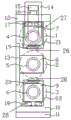
Fig. 1 is side of the present utility model agent structure schematic diagram.
Fig. 2 is positive agent structure schematic diagram of the present utility model.
Fig. 3 is the structural representation that three rolls of the utility model are vertical arrangement.
Fig. 4 is the structural representation that three rolls of the utility model are horizontal arrangement.
Fig. 5 is the structural representation that three rolls of the utility model are triangularly arranged.
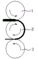
Fig. 6 is the principle schematic of the utility model three roller continuous rolling pole pieces.
The specific embodiment
As depicted in figs. 1 and 2, a kind of battery pole piece rolling equipment of the utility model, comprise base 11 and the frame 10 that is installed in base 11 two ends, frame 10 tops are equipped with footstock 12, nested first roll 1 that is provided with successively on the frame 10, the second roll 2 and the 3rd roll 3, form roll gap 26 between the first roll 1 and the second roll 2, form roll gap 26 between the second roll 2 and the 3rd roll 3, the first roll 1, the second roll 2 and the 3rd roll 3 are driven by motor 29, concrete, the first roll 1, the second roll 2 and the 3rd roll 3 respectively with the first motor 23, the second motor 24 connects with the 3rd motor 25.
The first roll 1, the second roll 2 and the 3rd roll 3 are vertical straight line and arrange (as shown in Figure 3), and the diameter of the first roll 1, the second roll 2 and the 3rd roll 3 is 100 mm~1500mm, and the diameter of three rolls can be identical, also can be different.
The first roll 1 is connected with the 3rd apparatus for adjusting position 28 with primary importance adjusting device 27 respectively with the 3rd roll 3.
Primary importance adjusting device 27 comprises for the clutch shaft bearing seat 7 of nested the first roll 1 and clutch shaft bearing 4, is installed in the first hydraulic cylinder 17 on the frame 10, is installed in the second hydraulic cylinder 16 on the footstock 12, and be installed in guide rail 21 under the clutch shaft bearing seat 7, on the second hydraulic cylinder 16 crossbeam 15 is installed, suspension ring 14 are installed between the central shaft of crossbeam 15 and the first roll 1, also are provided with the first wedge 19 between clutch shaft bearing seat 7 and the frame 10.
The 3rd apparatus for adjusting position 28 comprises for the 3rd bearing block 9 of nested the 3rd roll 3 and the 3rd bearing 6, is installed in the 3rd hydraulic cylinder 18 on the frame 10, be installed in the guide rail 22 under the 3rd bearing block 9, and be arranged on the second wedge 20 between the 3rd bearing block 9 and the frame 10.
The second roll 2 is nested in the second bearing 5, and the second bearing 5 is nested in the second bearing block 8, and the second bearing block 8 is nested and be fixed between frame 10 and the connecting plate 13.
Motor 29 is provided with three, and three motors are electrically connected with the first roll 1, the second roll 2 and the 3rd roll 3 respectively, and these three motors are referred to as respectively the first motor 23, the second motor 24 and the 3rd motor 25.
As shown in Figure 6, pole piece (is referred to as the first roll down station through slit wherein, accordingly, pole piece then is referred to as the first roll down station through another slit) the operation of rolling be the pre-operation of rolling of battery pole piece, the thickness of battery pole piece is rolled down near target thickness.Battery pole piece has a pole piece thickness bounce-back process between the first roll down station and the second roll down station, the battery pole piece thickness after the bounce-back is near target thickness.The second station operation of rolling is the roll forming process of battery pole piece, makes battery pole piece thickness reach target thickness.Through classification, twice continuous rolling, reduced battery pole piece thickness the bounce-back rate, improved battery pole piece compacted density, improved the uniformity of battery pole piece thickness.Use battery pole piece three-roll continuous rolling equipment carry out double rolling mill practice replace existing two rollers or four roller apparatus repeatedly, rolling mill practice repeatedly, can enhance productivity, reduce manufacturing cost.
During installation, footstock 12 is installed, fixedly footstock 12 and frame 10 above two frames 10; At footstock 12 the second hydraulic cylinder 16 is installed, at the second hydraulic cylinder 16 crossbeam 15 is installed, suspension ring 14 are installed between the central shaft of crossbeam 15 and the first roll 1.The central shaft of the first roll 1, the central shaft of the second roll 2, the central shaft of the 3rd roll 3 are linked to each other with the first motor 23, the second motor 24, the 3rd motor 25 respectively.
The main installation process of the first roll 1 part is: in two frames 10 the first wedge 19 is installed, and is regulated the up and down relative position on two inclined-planes of the first wedge 19, make the thickness of the first wedge 19 reach higher value; The central shaft of the first roll 1 and clutch shaft bearing 4 are nested in the middle of the clutch shaft bearing seat 7, from the top clutch shaft bearing seat 7 are installed in two frames 10.
The main installation process of the second roll 2 parts is: the central shaft of the second roll 2 is nested in the middle of the second bearing 5, the second bearing 5 is nested in the middle of the second bearing block 8, the second bearing block 8 is nested and be fixed between frame 10 and the connecting plate 13, and the position of the second roll 2 in frame 10 keeps fixing.
The main installation process of the 3rd roll 3 parts is: the central shaft of the 3rd roll 3 and the 3rd bearing 6 are nested in the middle of the 3rd bearing block 9; In frame 10 the 3rd hydraulic cylinder 18 is installed; Firm banking 11, fixed frame 10 on base 11, shift the frame 10 of the 3rd motor 25 sides onto on the base 11 correct position, the 3rd bearing block 9 is installed in the middle of two frames 10, shift the frame 10 of the 3rd motor 25 sides onto installation site, fix the frame 10 of the 3rd motor 25 sides at base 11.
Pressing force between rolls and roll gap 26 set with the adjusting embodiment and be described as follows: the setting and the regulative mode that see also pressure between Fig. 1 and Fig. 2 the first roll 1 and the second roll 2 and roll gap 26 are as follows.
The mode that tunes up roll gap 26 between the first roll 1 and the second roll 2 has two kinds.
The first: the central shaft of the first roll 1 and clutch shaft bearing 4 are nested in the middle of the clutch shaft bearing seat 7, after 17 releases of the first hydraulic cylinder, the second hydraulic cylinder 16 boosts, the plunger of the second hydraulic cylinder 16 heads on crossbeam 15, crossbeam 15 is holding in the palm suspension ring 14, suspension ring 14 are asking the central shaft of the first roll 1 to drive the first roll 1 and clutch shaft bearing seat 7 moves upward under the guiding of the first guide rail 21, reach the purpose that tunes up roll gap 26 between the first roll 1 and the second roll 2.
The second: the first wedge 19 is arranged between clutch shaft bearing seat 7 and the frame 10, by motor-driven the first wedge 19, the first wedge about in the of 19 parts do horizontal relative motion, form the combination of the first wedge 19 of differing heights, the purpose of reach setting, regulating roll gap 26 between the first roll 1 and the second roll 2.
The mode of turning roll gap 26 between the first roll 1 and the second roll 2 down is as follows: after 16 releases of the second hydraulic cylinder, the first hydraulic cylinder 17 boosts, the plunger of the first hydraulic cylinder 17 withstands footstock 12, because footstock 12 positions maintain static, then the first roll 1 and clutch shaft bearing seat 7 descend, close towards the second roll 2, reach the purpose of turning the first roll 1 and the second roll 2 roll gap 26 down.
When clutch shaft bearing seat 7, the first wedge 19, frame 10 close contact, the desired value that the roll gap 26 between the first roll 1 and the second roll 2 reaches setting no longer changes.
In addition, can realize pressure setting and adjusting between the first roll 1 and the second roll 2 by the pressure of regulation of hydraulic system the first hydraulic cylinder 17.
The mode of regulating roll gap 26 between the 3rd roll 3 and the second roll 2 has two kinds.
The first: after 18 releases of the 3rd hydraulic cylinder, the 3rd roll 3 and the 3rd bearing block 9 descend under the self gravitation effect, and the roll gap 26 between the 3rd roll 3 and the second roll 2 becomes large; And increase the pressure of the 3rd hydraulic cylinder 18, and the 3rd roll 3 and the 3rd bearing block 9 are close towards the second roll 2 under the second guide rail 22 guiding, and the roll gap 26 between the 3rd roll 3 and the second roll 2 diminishes.
The second, the second wedge 20 is arranged between the 3rd bearing block 9 and the frame 10, by motor-driven the second wedge 20, the second wedges about in the of 20 parts do horizontal relative motion, form the wedge combination of differing heights, reach the purpose of regulating roll gap 26 between the 3rd roll 3 and the second roll 2.When the 3rd bearing block 9, the second wedge 20 and frame 10 close contact, the desired value that the roll gap 26 between the 3rd roll 3 and the second roll 2 reaches setting no longer changes.By the roll gap 26 between the second wedge 20 control the 3rd rolls 3 and the second roll 2; Realize pressure setting and adjusting between the 3rd roll 3 and the second roll 2 by the pressure of regulation of hydraulic system the 3rd hydraulic cylinder 18; Final setting and the adjusting that realizes pressure, roll gap 26 between the 3rd roll 3 and the second roll 2.
Consulting Fig. 4 working method of the present utility model is: battery pole piece carries out double rolling or battery pole piece through the roll gap 26 between the roll gap 26 between the first roll 1 and the second pressure roller 2, the 3rd roll 3 and the second pressure roller 2 successively and can carry out double rolling through the roll gap 26 between the roll gap 26 between the 3rd roll 3 and the second pressure roller 2, the first roll 1 and the second roll 2 successively.
Wherein, the first roll 1, the second roll 2 and the 3rd roll 3 are arranged (as shown in Figure 3) except being the vertical straight line shown in this specific embodiment, can also be horizontal linear arrangement (as shown in Figure 4) or rounded projections arranged (as shown in Figure 5), structure and the vertical straight line homotaxy of horizontal linear arrangement and rounded projections arranged repeat no more here.
Need to prove: the first, the utility model is not particularly limited the type of drive of the first roll 1, the second roll 2, the 3rd roll 3, can select accessory commonly used, is connected by shaft coupling, reductor, motor.Number of motors also is not particularly limited, can be for the first roll 1, the second roll 2, the 3rd roll 3 configure separately three motors, namely the first motor 23, the second motor 24, the 3rd motor 25 also can configure a motor 29, then by gear drive, drive three roller rotational work.
The second, the utility model is not particularly limited the diameter of the first roll 1, the second roll 2, the 3rd roll 3, and the diameter of three rolls is 100mm~1500mm, and diameter can equate also can be unequal.
The 3rd, can the option and installment unwinding device before and after roll body structure of the present utility model, splicing equipment, correction detection control apparatus, tension force detection control apparatus, rim charge device for excising, dust arrester, static eraser, heater, scraper, thickness detection apparatus, wrap-up, battery pole piece carrying roller, and protective cover.
The according to the above description announcement of book and instruction, the utility model those skilled in the art can also carry out suitable change and modification to above-mentioned embodiment.Therefore, the specific embodiment that discloses and describe above the utility model is not limited to also should fall in the protection domain of claim of the present utility model modifications and changes more of the present utility model.In addition, although used some specific terms in this specification, these terms do not consist of any restriction to the utility model just for convenience of description.
Claims (10)
1. battery pole piece rolling equipment, it is characterized in that: comprise base (11) and be installed in the frame (10) at described base (11) two ends, described frame (10) top is equipped with footstock (12), nested the first roll (1) that is provided with successively on the described frame (10), the second roll (2) and the 3rd roll (3), form roll gap (26) between described the first roll (1) and described the second roll (2), form roll gap (26) between described the second roll (2) and described the 3rd roll (3), described the first roll (1), described the second roll (2) and described the 3rd roll (3) drive by motor (29).
2. battery pole piece rolling equipment according to claim 1 is characterized in that: described the first roll (1), the second roll (2) and the 3rd roll (3) are that vertical straight line is arranged, horizontal linear is arranged or rounded projections arranged.
3. battery pole piece rolling equipment according to claim 1, it is characterized in that: the diameter of described the first roll (1), described the second roll (2) and described the 3rd roll (3) is 100mm~1500mm.
4. battery pole piece rolling equipment according to claim 3, it is characterized in that: the diameter of described the first roll (1), described the second roll (2) and described the 3rd roll (3) is identical or different.
5. battery pole piece rolling equipment according to claim 1 is characterized in that: described the first roll (1) be connected the 3rd roll (3) and be connected with the 3rd apparatus for adjusting position (28) with primary importance adjusting device (27) respectively.
6. battery pole piece rolling equipment according to claim 5, it is characterized in that: described primary importance adjusting device (27) comprises the clutch shaft bearing seat (7) for nested the first roll (1) and clutch shaft bearing (4), be installed in the first hydraulic cylinder (17) on the described frame (10), be installed in the second hydraulic cylinder (16) on the described footstock (12) and be installed in guide rail (21) under the described clutch shaft bearing seat (7), crossbeam (15) is installed on described the second hydraulic cylinder (16), between the central shaft of described crossbeam (15) and the first roll (1) suspension ring (14) is installed.
7. battery pole piece rolling equipment according to claim 6 is characterized in that: also be provided with the first wedge (19) between described clutch shaft bearing seat (7) and the frame (10).
8. battery pole piece rolling equipment according to claim 5, it is characterized in that: described the 3rd apparatus for adjusting position (28) comprises for the 3rd bearing block (9) of nested the 3rd roll (3) and the 3rd bearing (6), is installed in the 3rd hydraulic cylinder (18) on the described frame (10), be installed in the guide rail (22) under described the 3rd bearing block (9), and be arranged on the second wedge (20) between described the 3rd bearing block (9) and the frame (10).
9. battery pole piece rolling equipment according to claim 1, it is characterized in that: described the second roll (2) is nested in the second bearing (5), described the second bearing (5) is nested in the second bearing block (8), and described the second bearing block (8) is nested and be fixed between described frame (10) and the connecting plate (13).
10. battery pole piece rolling equipment according to claim 1, it is characterized in that: described motor (29) is provided with three, and three described motors are electrically connected with described the first roll (1), described the second roll (2) and described the 3rd roll (3) respectively.
Priority Applications (1)
| Application Number | Priority Date | Filing Date | Title |
|---|---|---|---|
| CN 201220351433 CN202752330U (en) | 2012-07-19 | 2012-07-19 | Battery pole piece rolling device |
Applications Claiming Priority (1)
| Application Number | Priority Date | Filing Date | Title |
|---|---|---|---|
| CN 201220351433 CN202752330U (en) | 2012-07-19 | 2012-07-19 | Battery pole piece rolling device |
Publications (1)
| Publication Number | Publication Date |
|---|---|
| CN202752330U true CN202752330U (en) | 2013-02-27 |
Family
ID=47731525
Family Applications (1)
| Application Number | Title | Priority Date | Filing Date |
|---|---|---|---|
| CN 201220351433 Expired - Lifetime CN202752330U (en) | 2012-07-19 | 2012-07-19 | Battery pole piece rolling device |
Country Status (1)
| Country | Link |
|---|---|
| CN (1) | CN202752330U (en) |
Cited By (8)
| Publication number | Priority date | Publication date | Assignee | Title |
|---|---|---|---|---|
| CN106001115A (en) * | 2016-06-12 | 2016-10-12 | 河北德乐机械科技股份有限公司 | Roller staggered battery pole piece rolling device |
| CN106001116A (en) * | 2016-06-12 | 2016-10-12 | 河北德乐机械科技股份有限公司 | Battery pole piece rolling equipment with rolls convenient to detach |
| CN107999537A (en) * | 2018-01-17 | 2018-05-08 | 般若涅利(北京)装备技术有限公司 | The device and corresponding method that battery pole piece thickness rebounds after a kind of suppression roll-in |
| CN108568452A (en) * | 2017-03-11 | 2018-09-25 | 深圳格林德能源有限公司 | A kind of three roller pole piece roller mill of lithium ion battery full automatic closed type |
| CN110404980A (en) * | 2019-07-24 | 2019-11-05 | 深圳市信宇人科技股份有限公司 | Novel no extension precision rollers machine |
| CN111900324A (en) * | 2020-07-17 | 2020-11-06 | 合肥国轩高科动力能源有限公司 | Lithium battery pole piece rolling device |
| CN113546961A (en) * | 2021-07-14 | 2021-10-26 | 安徽凤杰金属资源有限公司 | Miniature asynchronous experimental rolling mill for producing metal ultrathin strip |
| CN114522980A (en) * | 2022-04-13 | 2022-05-24 | 东莞海裕百特智能装备有限公司 | Continuous rolling type battery pole piece roller machine with thickness control mechanism |
-
2012
- 2012-07-19 CN CN 201220351433 patent/CN202752330U/en not_active Expired - Lifetime
Cited By (9)
| Publication number | Priority date | Publication date | Assignee | Title |
|---|---|---|---|---|
| CN106001115A (en) * | 2016-06-12 | 2016-10-12 | 河北德乐机械科技股份有限公司 | Roller staggered battery pole piece rolling device |
| CN106001116A (en) * | 2016-06-12 | 2016-10-12 | 河北德乐机械科技股份有限公司 | Battery pole piece rolling equipment with rolls convenient to detach |
| CN108568452A (en) * | 2017-03-11 | 2018-09-25 | 深圳格林德能源有限公司 | A kind of three roller pole piece roller mill of lithium ion battery full automatic closed type |
| CN107999537A (en) * | 2018-01-17 | 2018-05-08 | 般若涅利(北京)装备技术有限公司 | The device and corresponding method that battery pole piece thickness rebounds after a kind of suppression roll-in |
| CN110404980A (en) * | 2019-07-24 | 2019-11-05 | 深圳市信宇人科技股份有限公司 | Novel no extension precision rollers machine |
| CN111900324A (en) * | 2020-07-17 | 2020-11-06 | 合肥国轩高科动力能源有限公司 | Lithium battery pole piece rolling device |
| CN113546961A (en) * | 2021-07-14 | 2021-10-26 | 安徽凤杰金属资源有限公司 | Miniature asynchronous experimental rolling mill for producing metal ultrathin strip |
| CN114522980A (en) * | 2022-04-13 | 2022-05-24 | 东莞海裕百特智能装备有限公司 | Continuous rolling type battery pole piece roller machine with thickness control mechanism |
| CN114522980B (en) * | 2022-04-13 | 2022-09-13 | 东莞海裕百特智能装备有限公司 | Continuous rolling type battery pole piece roller machine with thickness control mechanism |
Similar Documents
| Publication | Publication Date | Title |
|---|---|---|
| CN202752330U (en) | Battery pole piece rolling device | |
| CN103128101B (en) | Multi-dimensional controllable modularization six-roller mill | |
| CN204747120U (en) | High strength integral type levelling machine | |
| CN106863053A (en) | A kind of sheet band steel strip edge method for grinding and equipment for grinding | |
| CN201214111Y (en) | Steering roll with upper and lower uncoiling | |
| CN202967674U (en) | Cloth leveling device | |
| CN206184915U (en) | Tandem mill is used in steel band production | |
| CN2870185Y (en) | Device for rolling cell polar-piece roller support | |
| CN102151734A (en) | Burr pressing mechanism and method | |
| CN200939463Y (en) | Magnetic suspension rolling mill | |
| CN202539269U (en) | S-shaped roller leveling device | |
| CN203917418U (en) | Steel plate is depressed guide and guards | |
| CN204294665U (en) | A kind of single roller iron scale scavenge unit servo-actuated with uncoiler | |
| CN202411106U (en) | Battery pole piece rolling device | |
| CN101920281B (en) | Five-roll metal plate and strip straightening machine | |
| CN202846351U (en) | Shock-proof grinding head for on-line grinding roller device | |
| CN204208928U (en) | Quick roll-changing device | |
| CN202942909U (en) | Four-roll crusher | |
| CN201799374U (en) | Film-coating rubber roll bracket at furnace mouth | |
| CN203541084U (en) | Pneumatic control type roller mounting base | |
| CN201711386U (en) | Temper mill uncoiler movable support device | |
| CN204338581U (en) | A kind of roll roll-bending device | |
| CN203791339U (en) | Fourteen-roller rolling mill | |
| CN105290158A (en) | Rapid roll changing device | |
| CN209406403U (en) | Five roller mills |
Legal Events
| Date | Code | Title | Description |
|---|---|---|---|
| C14 | Grant of patent or utility model | ||
| GR01 | Patent grant | ||
| CX01 | Expiry of patent term |
Granted publication date: 20130227 |
|
| CX01 | Expiry of patent term |