CN202671169U - Flip tool for barrel-type workpiece - Google Patents
Flip tool for barrel-type workpiece Download PDFInfo
- Publication number
- CN202671169U CN202671169U CN 201220208731 CN201220208731U CN202671169U CN 202671169 U CN202671169 U CN 202671169U CN 201220208731 CN201220208731 CN 201220208731 CN 201220208731 U CN201220208731 U CN 201220208731U CN 202671169 U CN202671169 U CN 202671169U
- Authority
- CN
- China
- Prior art keywords
- barrel
- cylindrical work
- type workpiece
- fixed pulleys
- crossbeam
- Prior art date
- Legal status (The legal status is an assumption and is not a legal conclusion. Google has not performed a legal analysis and makes no representation as to the accuracy of the status listed.)
- Expired - Fee Related
Links
Images

Abstract
The utility model discloses a flip tool for a barrel-type workpiece. The flip tool for the barrel-type workpiece comprises a bracket for hanging the barrel-type workpiece. The bracket is horizontally and oppositely provided with two fixed pulleys at intervals. Each of the two fixed pulleys is provided with a steel wire rope. Two ends of the steel wire ropes are respectively fixed with bolt-type lifting rings used for corresponding connection with auxiliary holes arranged on two end faces of the barrel-type workpiece at intervals. The flip tool for the barrel-type workpiece is simple in structure. In the process of using, the two auxiliary holes arranged on two end faces of the barrel-type workpiece are respectively connected with two ends of the steel wire ropes wound over the fixed pulleys in a corresponding mode through the lifting rings. The flip tool for the barrel-type workpiece utilizes rotation of the fixed pulleys to drive the barrel-type workpiece through the steel wire ropes to achieve 360 degrees rotation, thereby avoiding the phenomenon that the barrel-type workpiece is scratched or collided in manual hauling. Spray coating of the barrel-type workpiece is free from dead angles, and thus the spray coating quality is improved. Simultaneously, the flip tool for the barrel-type workpiece can effectively avoid the accidents of colliding hurt and crushing hurt, and solve the major problem of potential safety hazard in manual hauling.
Description
Technical field
The utility model relates to a kind of upset frock be used to the large-scale cylindrical work that overturns.
Background technology
The surface lacquer operation of the large-scale cylindrical work in the existing high-voltage appliance switch need hang cylindrical shell and send into the japanning of japanning workshop again on Transport Desk, and the cylindrical shell that needs to overturn in spraying process is in order to spray to each position of cylindrical shell.Traditional method is to adopt a dead lift upset, not only increase workman's labour intensity, and adopt artificial upset that the event of colliding with very easily occurs to scratch, and there is the spraying dead angle, can't guarantee the coating quality of cylindrical work, simultaneously, the workpiece that manually overturns injures accident by a crashing object easily, has larger potential safety hazard.In addition, cylindrical work needs to be equipped with large-scale auxiliary lifting appliance in addition after spraying operation is finished, and between drying vehicle, the lifting of the secondary of cylindrical work has increased operational sequence, so that its production efficiency is lower with the cylindrical work handling.
The utility model content
The purpose of this utility model is: provide a kind of upset frock of cylindrical work, to solve the problem that the safety of artificial upset workpiece is lower, japanning is second-rate.
The technical solution of the utility model is: a kind of upset frock of cylindrical work, comprise the support for the suspention cylindrical work, on the support in the horizontal direction relative spacing be provided with two fixed pulleys, be respectively equipped with steel rope on two fixed pulleys, the two ends of steel rope be fixed with respectively for the cylindrical work both ends of the surface on the screw bolt-type suspension ring of the corresponding connection of auxiliary hole.
Described two fixed pulleys are hung on support by the rotating hoisting ring of correspondence setting respectively.
The column that described support is mainly split by relative spacing and the crossbeam that is connected across two column tops form, and described two fixed pulleys are suspended in the crossbeam bottom.
Be installed with two positions at the bottom of described crossbeam relative spacing and adjust plate, two positions is adjusted plate all along the crossbeam longitudinal extension, be arranged with adjusting hole along its bearing of trend respectively on two positions adjustment plate, described two fixed pulleys are suspended in the adjusting hole of relevant position adjustment plate by rotating hoisting ring respectively according to the length of cylindrical work.
Described support is made by steel-pipe welding.
Described crossbeam is made by I-beam section.
Be fixed with respectively for the suspension ring plate that is connected with loop wheel machine at the two ends on described crossbeam top.
Upset frock of the present utility model simple in structure, during use, its two auxiliary holes that relative spacing on end face of cylindrical work two ends is laid are respectively with suspension ring and a corresponding connection in two ends of walking around the steel rope of fixed pulley, utilize the rotation of fixed pulley to realize 360 ° rotation by steel rope drive cylindrical work, avoided a dead lift upset to scratch the cylindrical work surface of colliding with, and spraying work is without the dead angle, thereby improved the coating quality of cylindrical work, simultaneously, the upset that utilizes frock to finish cylindrical work has effectively been avoided damaging, injure the generation of accident by a crashing object, solved the large problem of a dead lift potential safety hazard.
Description of drawings
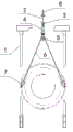
Fig. 1 is the structural representation of the utility model cylindrical work upset frock specific embodiment;
Fig. 2 is that the K of Fig. 1 is to view;
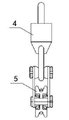
Fig. 3 is the connection structure scheme drawing of fixed pulley and rotating hoisting ring among Fig. 1.
The specific embodiment
The implementation of cylindrical work upset frock of the present utility model is Fig. 1 for example, Fig. 2, shown in Figure 3, it comprises by steel-pipe welding makes and two stands 1 and the fixed mount of relative spacing setting is located at the crossbeam 2 that two stands 1 top is made by I-beam section, crossbeam 2 bottom relative spacings are provided with two positions and adjust plate 3, this two positions is adjusted plate 3 and is all extended along crossbeam 2 longitudinallies, on two positions adjustment plate 3, be laid with some position adjustment hole along its bearing of trend interval respectively, in two positions adjustment plate 3 corresponding position adjustment hole, be hung with rotating hoisting ring 4 by hook respectively, be connected with respectively fixed pulley 5 in two rotating hoisting rings, 4 bottoms, be equipped with steel rope 6 on two fixed pulleys 5, the two ends of two steel ropes 6 be fixed with respectively for cylindrical work two ends end face on the screw bolt-type suspension ring 7 of the interval corresponding connection of auxiliary hole of offering.Also be fixed with respectively for the suspension ring plate 8 that connects loop wheel machine at the two ends on crossbeam top.
Upset frock of the present utility model in use, length according to cylindrical work, two fixed pulleys are suspended on respectively the position to be adjusted in the plate 3 in the corresponding position adjustment hole, steel rope 6 passes fixed pulley 5, its two ends are connected in the auxiliary hole that lay at the interval on the cylindrical work end face with the screw bolt-type suspension ring respectively, make rotating hoisting ring 7 and steel rope 6 shapes at a certain angle.The frock of should overturning places the japanning workshop, the cylindrical work surface is through degreasing, it is suspended in crossbeam 2 belows by two ends with the steel rope 6 that screw bolt-type suspension ring 7 connect after the flushing, carry out paint work, in the spraying process, can cooperate 360 ° of rotations that realize cylindrical work by steel rope 6 and the fixed pulley 5 that is connected to the cylindrical work two ends, assurance sprays evenly and paints without the dead angle, improved the japanning quality, and cross winding can not occur in the steel rope 6 at two ends, during spraying operation, cylindrical work is in vacant state all the time, has alleviated workman's labour intensity, avoid scratching the generation of the dangerous situation that collides with and manually overturn, guaranteed the safety in the work.After paint work was finished, directly with the overhead traveling crane suspension ring plate 8 at crossbeam 2 two ends of slinging, the frock of should overturning connection cylindrical work transported between drying vehicle together, has avoided the secondary lifting, has improved work efficiency.
Claims (7)
1. the upset frock of a cylindrical work, it is characterized in that, comprise the support for the suspention cylindrical work, on the support in the horizontal direction relative spacing be provided with two fixed pulleys, be respectively equipped with steel rope on two fixed pulleys, the two ends of steel rope be fixed with respectively for the cylindrical work both ends of the surface on the screw bolt-type suspension ring of the corresponding connection of auxiliary hole.
2. the upset frock of cylindrical work according to claim 1 is characterized in that, described two fixed pulleys are hung on support by the rotating hoisting ring of correspondence setting respectively.
3. the upset frock of cylindrical work according to claim 2 is characterized in that, the column that described support is mainly split by relative spacing and the crossbeam that is connected across two column tops form, and described two fixed pulleys are suspended in the crossbeam bottom.
4. the upset frock of cylindrical work according to claim 3, it is characterized in that, be installed with two positions at the bottom of described crossbeam relative spacing and adjust plate, two positions is adjusted plate all along the crossbeam longitudinal extension, be arranged with adjusting hole along its bearing of trend respectively on two positions adjustment plate, described two fixed pulleys are suspended in the adjusting hole of relevant position adjustment plate by rotating hoisting ring respectively according to the length of cylindrical work.
5. the upset frock of cylindrical work according to claim 1 is characterized in that, described support is made by steel-pipe welding.
6. the upset frock of cylindrical work according to claim 1 is characterized in that, described crossbeam is made by I-beam section.
7. the upset frock of cylindrical work according to claim 1 is characterized in that, is fixed with respectively for the suspension ring plate that is connected with loop wheel machine at the two ends on described crossbeam top.
Priority Applications (1)
| Application Number | Priority Date | Filing Date | Title |
|---|---|---|---|
| CN 201220208731 CN202671169U (en) | 2012-05-10 | 2012-05-10 | Flip tool for barrel-type workpiece |
Applications Claiming Priority (1)
| Application Number | Priority Date | Filing Date | Title |
|---|---|---|---|
| CN 201220208731 CN202671169U (en) | 2012-05-10 | 2012-05-10 | Flip tool for barrel-type workpiece |
Publications (1)
| Publication Number | Publication Date |
|---|---|
| CN202671169U true CN202671169U (en) | 2013-01-16 |
Family
ID=47492086
Family Applications (1)
| Application Number | Title | Priority Date | Filing Date |
|---|---|---|---|
| CN 201220208731 Expired - Fee Related CN202671169U (en) | 2012-05-10 | 2012-05-10 | Flip tool for barrel-type workpiece |
Country Status (1)
| Country | Link |
|---|---|
| CN (1) | CN202671169U (en) |
Cited By (6)
| Publication number | Priority date | Publication date | Assignee | Title |
|---|---|---|---|---|
| CN104891370A (en) * | 2015-05-05 | 2015-09-09 | 青岛港国际股份有限公司 | Tire replacement machine |
| CN106365027A (en) * | 2016-10-25 | 2017-02-01 | 苏州天沃科技股份有限公司 | Hoisting and overturning tool of high-pressure heater pipe system |
| CN106510102A (en) * | 2016-12-30 | 2017-03-22 | 东莞市鸿程机械有限公司 | Automatic rubber coating device of rope area |
| CN106743419A (en) * | 2016-12-01 | 2017-05-31 | 广州三五汽车部件有限公司 | Turning-up devices before workpiece |
| CN106986291A (en) * | 2017-05-12 | 2017-07-28 | 黄坤坤 | Large scale prefabricated wallboard overturns construction method for hanging in the air |
| CN109454583A (en) * | 2018-11-25 | 2019-03-12 | 格特拉克(江西)传动系统有限公司 | A kind of catching device of shaft assembly dismantling |
-
2012
- 2012-05-10 CN CN 201220208731 patent/CN202671169U/en not_active Expired - Fee Related
Cited By (9)
| Publication number | Priority date | Publication date | Assignee | Title |
|---|---|---|---|---|
| CN104891370A (en) * | 2015-05-05 | 2015-09-09 | 青岛港国际股份有限公司 | Tire replacement machine |
| CN107244635A (en) * | 2015-05-05 | 2017-10-13 | 青岛港国际股份有限公司 | A kind of tyre changing machines |
| CN107244635B (en) * | 2015-05-05 | 2019-05-21 | 青岛港国际股份有限公司 | A kind of tyre changing machines |
| CN106365027A (en) * | 2016-10-25 | 2017-02-01 | 苏州天沃科技股份有限公司 | Hoisting and overturning tool of high-pressure heater pipe system |
| CN106365027B (en) * | 2016-10-25 | 2018-03-23 | 张化机(苏州)重装有限公司 | The hoisting flip tool of high-pressure heater piping |
| CN106743419A (en) * | 2016-12-01 | 2017-05-31 | 广州三五汽车部件有限公司 | Turning-up devices before workpiece |
| CN106510102A (en) * | 2016-12-30 | 2017-03-22 | 东莞市鸿程机械有限公司 | Automatic rubber coating device of rope area |
| CN106986291A (en) * | 2017-05-12 | 2017-07-28 | 黄坤坤 | Large scale prefabricated wallboard overturns construction method for hanging in the air |
| CN109454583A (en) * | 2018-11-25 | 2019-03-12 | 格特拉克(江西)传动系统有限公司 | A kind of catching device of shaft assembly dismantling |
Similar Documents
| Publication | Publication Date | Title |
|---|---|---|
| CN202671169U (en) | Flip tool for barrel-type workpiece | |
| CN205527406U (en) | Hoist device for building portable | |
| CN201460182U (en) | Construction trolley on trolley line of bridge crane | |
| CN105003082A (en) | Glass curtain wall mounting equipment and glass curtain mounting method | |
| CN202688879U (en) | Arch steel tower coating platform running with arch | |
| CN107128817A (en) | Auto parts machinery processes special mobile formula single armed loop wheel machine | |
| CN202181165U (en) | Cross lifting beam for box type transformer | |
| CN205906926U (en) | Special stone tongs of precious stones | |
| CN201195149Y (en) | Spray painting apparatus for top cover of motorcycle | |
| CN105110205A (en) | Reverse disassembling method for tower crane | |
| CN106185626B (en) | Turning device and method are aided in suitable for the packaged type of large volume and wt pts | |
| CN103350959B (en) | Derrick car | |
| CN203281458U (en) | Workpiece suspension bracket | |
| CN206307891U (en) | For the Lift-on/Lift-off System of large-scale wind electricity product | |
| CN110862023A (en) | Construction method of mechanical hoisting device | |
| CN206814280U (en) | A kind of adjustable gantry crane | |
| CN102530706B (en) | Angle-shaped hanging basket | |
| CN104724624B (en) | A kind of hoist engine hanging method of small space inner structure | |
| CN202099007U (en) | Angular lifting basket | |
| CN203843701U (en) | Hanging device for trunnion shot blasting | |
| CN108033361A (en) | A kind of overhead crane with electric hoists | |
| CN219637274U (en) | Heat treatment tool for planet carrier | |
| CN204138042U (en) | Cable reel supporting rack device | |
| CN104386592B (en) | A kind of special lorry-mounted crane of railway | |
| CN111687800B (en) | Electric locomotive rod member maintenance tool and method |
Legal Events
| Date | Code | Title | Description |
|---|---|---|---|
| C14 | Grant of patent or utility model | ||
| GR01 | Patent grant | ||
| CF01 | Termination of patent right due to non-payment of annual fee | ||
| CF01 | Termination of patent right due to non-payment of annual fee |
Granted publication date: 20130116 Termination date: 20180510 |