CN202670872U - Large-diameter film rewinder - Google Patents
Large-diameter film rewinder Download PDFInfo
- Publication number
- CN202670872U CN202670872U CN 201220291508 CN201220291508U CN202670872U CN 202670872 U CN202670872 U CN 202670872U CN 201220291508 CN201220291508 CN 201220291508 CN 201220291508 U CN201220291508 U CN 201220291508U CN 202670872 U CN202670872 U CN 202670872U
- Authority
- CN
- China
- Prior art keywords
- rotating shaft
- correspondence
- rolling
- rewinding operation
- major diameter
- Prior art date
- Legal status (The legal status is an assumption and is not a legal conclusion. Google has not performed a legal analysis and makes no representation as to the accuracy of the status listed.)
- Expired - Fee Related
Links
Images
Landscapes
- Replacement Of Web Rolls (AREA)
Abstract
The utility model provides a large-diameter film rewinder. The large-diameter film rewinder comprises a base and an unwinding mechanism, a corrective mechanism and a winding mechanism which are respectively arranged on the base, wherein the unwinding mechanism, the corrective mechanism and the winding mechanism are tightly arranged along the film unwinding direction in sequence and work synchronously by matching with one other in sequence. By adopting the scheme, the large-diameter film rewinder provided by the utility model has the biggest advantages that the motion is stable and high efficient, and the winding diameter can be up to about 1.5 m, compared with the prior art, the rewinding requirement of films with a diameter more than 0.8 m can be met; and moreover, the production efficiency is high.
Description
Technical field
The utility model relates to the technical field of membrane production equipment, refers in particular to a kind of major diameter film rewinding operation machine.
Background technology
At present, the film rewinding operation machine on the existing market only batches the type of diameter below 0.8 meter, and this can not satisfy its need of production for present large diameter film rewinding operation (more than 0.8 meter) demand.Therefore, follow now the development of electromechanical integration, how to produce a film rewinding operation machine that can satisfy to batch diameter more than 0.8 meter, become researchist's problem anxious to be resolved.
Summary of the invention
The purpose of this utility model is to overcome the deficiencies in the prior art, and a kind of reliable, stable action reasonable in design, efficient major diameter film rewinding operation machine are provided.
For achieving the above object, technical scheme provided by the utility model is: a kind of major diameter film rewinding operation machine, it includes support and is installed in respectively unreeling structure, deviation correction mechanism, rolling-up mechanism on this support, wherein, described unreeling structure, deviation correction mechanism, rolling-up mechanism are along thin-film unreeling direction successively close-packed arrays, and cooperate successively synchronous working between them.
Described unreeling structure includes two back plates opposite each other, unreels rotating shaft, drg, and wherein, the described rotating shaft correspondence that unreels is located between two back plates, and joins with this two back plate respectively, and simultaneously, the drg correspondence is located at this end that unreels rotating shaft.
Described deviation correction mechanism includes biside plate opposite each other, transition axis, rubber roll, sensor, wherein, connect by many joint pins between the described biside plate, simultaneously, transition axis and rubber roll are located between this biside plate in parallel with each other, and join with this biside plate respectively; Described rubber roll is positioned at the top of biside plate, and simultaneously, correspondence is equipped with a sensor below the end of this rubber roll; Described transition axis has the many both sides, below that are positioned at rubber roll, and symmetrically.
Described rolling-up mechanism includes two stay bearing plates opposite each other, rolling rotating shaft, motor, wherein, described rolling rotating shaft correspondence is located between two stay bearing plates, and join with this two stay bearing plate respectively, simultaneously, this rolling rotating shaft is joined by synchronizing wheel and Timing Belt and motor, by this motor-driven rotation.
One side correspondence of described back plate is provided with swing span.
On the described side plate electric eye is installed, and this electric eye correspondence is located at the top of transition axis.
The utility model is after having adopted such scheme, its great advantage is the utility model stable action, efficient, and importantly it batches diameter and can reach about 1.5 meters, and this compares present technology, the utility model can satisfy the film rewinding operation demand more than 0.8 meter, and production efficiency is high.
Description of drawings
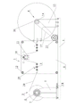
Fig. 1 is schematic diagram of the present utility model.
The specific embodiment
The utility model is described in further detail below in conjunction with specific embodiment.
Shown in accompanying drawing 1, the described major diameter film rewinding operation of the present embodiment machine, it includes support 1 and is installed in respectively unreeling structure 2, deviation correction mechanism 3, rolling-up mechanism 4 on this support 1, wherein, the described unreeling structure 2 of the present embodiment, deviation correction mechanism 3, rolling-up mechanism 4 are along thin-film unreeling direction successively close-packed arrays, and cooperate successively synchronous working between them.The described unreeling structure 2 of the present embodiment includes two back plates 5 opposite each other, unreels rotating shaft 6, drg 7, wherein, described rotating shaft 6 correspondences that unreel are located between two back plates 5, and join with this two back plate 5 respectively, simultaneously, drg 7 correspondences are located at the end that this unreels rotating shaft 6, are used for the usefulness of regulating unwinding tension and stopping; In addition, a side correspondence of the described back plate 5 of the present embodiment is provided with swing span 18, so that back plate 5 can pass through swing span 18 translations.The described deviation correction mechanism 3 of the present embodiment includes biside plate opposite each other 8, transition axis 9, rubber roll 10, sensor 11, wherein, connect by four joint pins 12 between the described biside plate 8, simultaneously, transition axis 9 and rubber roll 10 are located between this biside plate 8 in parallel with each other, and join with this biside plate 8 respectively; Described rubber roll 10 is positioned at the top of biside plate 8, and simultaneously, correspondence is equipped with a sensor 11 below the end of this rubber roll 10; Described transition axis 9 has the many both sides, below that are positioned at rubber roll 10, and symmetrically, simultaneously, the present embodiment correspondence above a side transition axis 9 is provided with an electric eye 19, for detection of film sideslip whether.The described rolling-up mechanism 3 of the present embodiment includes two stay bearing plates 13, rolling rotating shaft 14, motor 15 opposite each other, wherein, the shape of described two stay bearing plates 13 is L-type, one end and support 1 are fixedly connected, and its other end is fixedly connected with corresponding side plate 8 edges, and rolling rotating shaft 14 correspondences are located between two stay bearing plates 13, and join with this two stay bearing plate 13 respectively, simultaneously, this rolling rotating shaft 14 is joined with motor 15 by synchronizing wheel 16 and Timing Belt 17, drives rotation by this motor 15.After adopting above scheme, during work, film 20 is at first unreeling through unreeling structure 2 in the drive of motor 15, film 20 after unreeling afterwards is successively after the correction of the front end transition axis 9 of deviation correction mechanism 3, rubber roll 10, rear end transition axis 9, finally carry out rolling by rolling-up mechanism 4, finish the rewinding process of film 20.In a word, in sum, the utility model is by the orderly cooperation of 4 of unreeling structures 2, deviation correction mechanism 3, rolling-up mechanism, so that its stable action is reliable, efficient is high, and of paramount importance be that the diameter that batches of the present utility model can reach about 1.5 meters, this compares present technology, the utility model can satisfy the film rewinding operation demand more than 0.8 meter, can bring huge economic benefit for enterprise, is worthy to be popularized.
The examples of implementation of the above are the preferred embodiment of the utility model only, are not to limit practical range of the present utility model with this, therefore the variation that all shapes according to the utility model, principle are done all should be encompassed in the protection domain of the present utility model.
Claims (6)
1. major diameter film rewinding operation machine, it is characterized in that: it includes support (1) and is installed in respectively unreeling structure (2), deviation correction mechanism (3), rolling-up mechanism (4) on this support (1), wherein, described unreeling structure (2), deviation correction mechanism (3), rolling-up mechanism (4) are along thin-film unreeling direction successively close-packed arrays, and cooperate successively synchronous working between them.
2. a kind of major diameter film rewinding operation machine according to claim 1, it is characterized in that: described unreeling structure (2) includes two back plates (5) opposite each other, unreels rotating shaft (6), drg (7), wherein, described rotating shaft (6) correspondence that unreels is located between two back plates (5), and join with this two back plate (5) respectively, simultaneously, drg (7) correspondence is located at the end that this unreels rotating shaft (6).
3. a kind of major diameter film rewinding operation machine according to claim 1, it is characterized in that: described deviation correction mechanism (3) includes biside plate opposite each other (8), transition axis (9), rubber roll (10), sensor (11), wherein, connect by many joint pins (12) between the described biside plate (8), simultaneously, transition axis (9) and rubber roll (10) are located between this biside plate (8) in parallel with each other, and join with this biside plate (8) respectively; Described rubber roll (10) is positioned at the top of biside plate (8), and simultaneously, correspondence is equipped with a sensor (11) in the below, end of this rubber roll (10); Described transition axis (9) has the many both sides, below that are positioned at rubber roll (10), and symmetrically.
4. a kind of major diameter film rewinding operation machine according to claim 1, it is characterized in that: described rolling-up mechanism (3) includes two stay bearing plates (13) opposite each other, rolling rotating shaft (14), motor (15), wherein, described rolling rotating shaft (14) correspondence is located between two stay bearing plates (13), and join with this two stay bearing plate (13) respectively, simultaneously, this rolling rotating shaft (14) is joined with motor (15) by synchronizing wheel (16) and Timing Belt (17), drives rotation by this motor (15).
5. a kind of major diameter film rewinding operation machine according to claim 2, it is characterized in that: a side correspondence of described back plate (5) is provided with swing span (18).
6. a kind of major diameter film rewinding operation machine according to claim 3 is characterized in that: electric eye (19) is installed on the described side plate (8), and this electric eye (19) correspondence is located at the top of transition axis (9).
Priority Applications (1)
| Application Number | Priority Date | Filing Date | Title |
|---|---|---|---|
| CN 201220291508 CN202670872U (en) | 2012-06-20 | 2012-06-20 | Large-diameter film rewinder |
Applications Claiming Priority (1)
| Application Number | Priority Date | Filing Date | Title |
|---|---|---|---|
| CN 201220291508 CN202670872U (en) | 2012-06-20 | 2012-06-20 | Large-diameter film rewinder |
Publications (1)
| Publication Number | Publication Date |
|---|---|
| CN202670872U true CN202670872U (en) | 2013-01-16 |
Family
ID=47491790
Family Applications (1)
| Application Number | Title | Priority Date | Filing Date |
|---|---|---|---|
| CN 201220291508 Expired - Fee Related CN202670872U (en) | 2012-06-20 | 2012-06-20 | Large-diameter film rewinder |
Country Status (1)
| Country | Link |
|---|---|
| CN (1) | CN202670872U (en) |
Cited By (2)
| Publication number | Priority date | Publication date | Assignee | Title |
|---|---|---|---|---|
| CN104260552A (en) * | 2014-09-29 | 2015-01-07 | 瑞安市海燕印刷包装机械有限公司 | Automatic correcting mechanism for vertical film laminator |
| CN107686021A (en) * | 2017-09-18 | 2018-02-13 | 张家港爱铝铝箔科技有限公司 | A kind of semi-automatic high speed winder of aluminium foil preservative film |
-
2012
- 2012-06-20 CN CN 201220291508 patent/CN202670872U/en not_active Expired - Fee Related
Cited By (2)
| Publication number | Priority date | Publication date | Assignee | Title |
|---|---|---|---|---|
| CN104260552A (en) * | 2014-09-29 | 2015-01-07 | 瑞安市海燕印刷包装机械有限公司 | Automatic correcting mechanism for vertical film laminator |
| CN107686021A (en) * | 2017-09-18 | 2018-02-13 | 张家港爱铝铝箔科技有限公司 | A kind of semi-automatic high speed winder of aluminium foil preservative film |
Similar Documents
| Publication | Publication Date | Title |
|---|---|---|
| CN102931430B (en) | Full-automatic battery cell winding device | |
| CN203150668U (en) | Coiling device | |
| CN201638908U (en) | Full-automatic battery core winding device | |
| CN102530614A (en) | Automatic splicing and unreeling device | |
| CN108461826B (en) | Constant-speed winding needle combination mechanism | |
| CN202564490U (en) | Lithium battery lamination mold | |
| CN202670872U (en) | Large-diameter film rewinder | |
| CN202592210U (en) | Vane overturn vehicle for wind driven generator | |
| CN203830233U (en) | Base membrane flattening device | |
| CN205099034U (en) | Can be just reverse roll battery sheet roll membrane machine unwinding mechanism | |
| CN205790245U (en) | The coiler device of lithium ionic cell winding machine | |
| CN203306803U (en) | Flattening assisting device with traction and rolling functions | |
| CN204173646U (en) | Laminating machine and barrier film blowing thereof and tension control structure | |
| CN102241073B (en) | Full-automatic die-cutting feeding, material-receiving and discharging mechanism for lithium battery pole piece | |
| CN204148281U (en) | A kind of winding/unwinding device of double automation | |
| CN206364104U (en) | A kind of battery electrode group clamping apparatus of board-like whole lug mechanism and the application mechanism | |
| CN202050031U (en) | Winding mechanism of laminating machine | |
| CN105855325A (en) | Lithium ion battery tab bending correction device | |
| CN203004398U (en) | Accordion pocket manufacturing machine | |
| CN106429563B (en) | A kind of membrane coiler structure of glass film production line | |
| CN211062809U (en) | Feeding device of lithium battery | |
| CN102593523A (en) | Semi-automatic lithium ion battery laminating device | |
| CN202651265U (en) | Guide device for preventing battery electrode pieces from creasing | |
| CN203061388U (en) | Coating machine | |
| CN207572476U (en) | A kind of pre- winding apparatus of lithium battery electric core active |
Legal Events
| Date | Code | Title | Description |
|---|---|---|---|
| C14 | Grant of patent or utility model | ||
| GR01 | Patent grant | ||
| CF01 | Termination of patent right due to non-payment of annual fee |
Granted publication date: 20130116 Termination date: 20150620 |
|
| EXPY | Termination of patent right or utility model |