CN202598301U - Universal projection lamp - Google Patents
Universal projection lamp Download PDFInfo
- Publication number
- CN202598301U CN202598301U CN2012201416148U CN201220141614U CN202598301U CN 202598301 U CN202598301 U CN 202598301U CN 2012201416148 U CN2012201416148 U CN 2012201416148U CN 201220141614 U CN201220141614 U CN 201220141614U CN 202598301 U CN202598301 U CN 202598301U
- Authority
- CN
- China
- Prior art keywords
- radiator
- circuit board
- pcb circuit
- projecting lamp
- universal
- Prior art date
- Legal status (The legal status is an assumption and is not a legal conclusion. Google has not performed a legal analysis and makes no representation as to the accuracy of the status listed.)
- Expired - Fee Related
Links
Images

Abstract
The utility model discloses a universal projection lamp which comprises a radiator, a printed circuit board (PCB) circuit board and a driving power supply. The PCB circuit board is arranged on the radiator and electrically connected with the driving power supply, a plurality of light-emitting diode (LED) lighting chips forming a matrix are arranged on the PCB circuit board, a lens matched with the LED lighting chips of the matrix is arranged on the PCB circuit board, a power supply support is arranged on the radiator, two ends of the power supply support are connected with the radiator movably, and the driving power supply is fixed on the power supply support. A corner support is connected on the power supply support in movable mode, and a fixing sleeve for fixing the universal projection lamp is connected onto the corner support through a fastening piece. The universal projection lamp has the advantages of being capable of achieving universal adjustment of the light projection directions, simple in structure and convenient to adjust.
Description
Technical field
The utility model relates to lighting device, relates in particular to a kind of universal projecting lamp.
Background technology
The projecting lamp of convention is to make the light fixture of specifying the projecting environment of illumination on the face to be illuminated.Claim spotlight again.Usually, it can aim at any direction, and possesses the structure that does not receive weather influence.Be mainly used in ore deposit, large tracts of land operation field, contour of building, stadium, viaduct, monument, park and flower bed etc.Therefore, the large area lighting light fixture of nearly all outdoor application all can be regarded projecting lamp as.Projecting lamp both can singlely be installed and used, and also can many lamps combines to install concentratedly on the pole more than the 20m, constituted the high mast lighting device.But this device maintains, reduces the characteristics such as lamp stand and floor space except centralized maintenance handsome in appearance, and biggest advantage is that illumination functions is strong.When light throwed from eminence, the spatial brightness of environment was high, the light wide coverage; Give the people sensation in a kind of similar daytime, therefore higher lighting quality and visual effect are arranged, yet; Projecting lamp of the prior art, its projecting direction adjustability is poor, and for the adjustable projecting lamp of some directions; Its complex structure is regulated simple and conveniently inadequately, can not satisfy the hommization requirement.
Summary of the invention
The purpose of the utility model is effectively to overcome above-mentioned deficiency, and a kind of universal projecting lamp is provided; This universal projecting lamp can be adjusted projecting direction arbitrarily, and is simple in structure, easy to adjust.
The technical scheme of the utility model is achieved in that it comprises radiator, PCB circuit board and driving power; Wherein, Said PCB circuit board is installed on the radiator and with driving power and electrically connects; The LED luminescence chip of a plurality of formation matrixes is installed on the PCB circuit board, on the PCB circuit board, be equipped with one with the suitable lens of LED luminescence chip of said matrix, radiator is provided with a power shelf; The two ends of power shelf and said radiator flexibly connect, and said driving power is fixed on the power shelf; Be connected with a corner support on the said power shelf, on the corner support through securing member be connected with one be used for fixing universal projecting lamp fixed muffle.
In the said structure; Said radiator comprises that heat-radiating substrate reaches and the integrated radiating ribs of radiator base plate; Radiating ribs is arranged at the back side of heat-radiating substrate, and said PCB circuit board is installed on the front of heat-radiating substrate, and the last lower limb of said heat-radiating substrate also is provided with radiator frame body.
In the said structure, said fixed muffle comprises the first semicircle sleeve and the second semicircle sleeve, and the said first semicircle sleeve and the second semicircle sleeve are connected to form circular sleeve shape structure through bolt, and the said first semicircle sleeve is connected with the corner support through bolt.
In the said structure, be provided with sealing ring between said PCB circuit board and the lens.
In the said structure, the two ends of said power shelf and said radiator are rotationally connected.
In the said structure, the two ends and the power shelf of said corner support are rotationally connected.
The beneficial effect of the utility model is: one of which, the utility model connect a corner support on power shelf; Can relatively rotate between corner support and the power shelf; And radiator flexibly connects with power shelf, thus, can on the X axle, freely adjust the angle of inclination of radiator; In addition, be rotationally connected through bolt between fixed muffle and the corner support, therefore, the integral body that radiator and power shelf etc. are formed can be on Y direction free angle of inclination; Simultaneously, in use, fixed muffle is sheathed on again on the vertical fixed bar; Whole universal projecting lamp can rotate freely on the Z axle, and by this, the universal projecting lamp of the utility model can be realized the universal adjustment of light projecting direction; And it is simple in structure, and is easy to adjust; Two, radiator is the radiator structure of being made up of substrate and radiating ribs, and its good heat dissipation effect can derive the heat of assembling on the heat-radiating substrate fast, has guaranteed the service life of LED luminescence chip; Three, between said PCB circuit board and lens, be provided with sealing ring, the sealing circle makes projecting lamp have favorable waterproof property, avoids water or dust impurity to get into the serviceability that lens influence projecting lamp.
Description of drawings
Fig. 1 is the explosive view of the utility model
Fig. 2 is the utility model neutral body figure
The specific embodiment
Below in conjunction with accompanying drawing and embodiment the utility model is done further to describe.
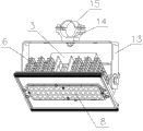
Referring to figs. 1 through shown in Figure 2; The utility model has disclosed a kind of universal projecting lamp, and this universal projecting lamp can be adjusted projecting direction arbitrarily, and it comprises radiator, PCB circuit board 11 and driving power 3; Wherein, Said PCB circuit board 11 is fixedly installed on the radiator through screw and electrically connects with driving power 3, and the LED luminescence chip of a plurality of formation matrixes is installed on the PCB circuit board 11, on PCB circuit board 11, be equipped with one with the suitable lens 8 of LED luminescence chip of said matrix; The edge of lens 8 is provided with through hole; In through hole, be fixedly connected with PCB circuit board 11, be provided with sealing ring 10 between said PCB circuit board 11 and the lens 3, guarantee that internal circuit and LED luminescence chip do not receive external environment influence through screw 9; Radiator is provided with a power shelf 5, and the two ends of power shelf 5 and said radiator flexibly connect, and be preferable, and the two ends of power shelf 5 are rotationally connected through bolt 4 and said radiator both sides, and said driving power 3 is fixed on the power shelf 5; Be connected with a corner support 13 on the said power shelf 5, the two ends of corner support 13 and power shelf 5 are rotationally connected through bolt 4, on the corner support 13 through bolt 2 be connected with one be used for fixing universal projecting lamp fixed muffle.
Radiator comprises that heat-radiating substrate 7 reaches and radiator base plate 7 integrated radiating ribs 6; Radiating ribs 6 is arranged at the back side of heat-radiating substrate 7; Said PCB circuit board 11 is installed on the front of heat-radiating substrate 7, and the last lower limb of said heat-radiating substrate 7 also is provided with radiator frame body 12.Fixed muffle comprises the first semicircle sleeve 14 and the second semicircle sleeve 15, and the said first semicircle sleeve 14 and the second semicircle sleeve 15 are connected to form circular sleeve shape structure through bolt 1, and 14 in said first semicircle cover passes through bolt 2 and is connected with corner support 13.
Because the utility model connects a corner support 13 on power shelf, can relatively rotate between corner support 13 and the power shelf, and radiator flexibly connects with power shelf 5, thus, can on the X axle, freely adjust the angle of inclination of radiator; In addition, be rotationally connected through bolt 2 between fixed muffle and the corner support 13, therefore, the integral body that radiator and power shelf 5 etc. are formed can be on Y direction free angle of inclination; Simultaneously, in use, fixed muffle is sheathed on again on the vertical fixed bar; Whole universal projecting lamp can rotate freely on the Z axle, and by this, the universal projecting lamp of the utility model can be realized the universal adjustment of light projecting direction; And it is simple in structure, and is easy to adjust; Secondly, radiator be the radiator structure of being made up of heat-radiating substrate 7 and radiating ribs 6, its good heat dissipation effect can guarantee the service life of LED luminescence chip fast with the heat derivation of gathering on the heat-radiating substrate 7; Once more, between said PCB circuit board 11 and lens 8, be provided with sealing ring 10, sealing circle 10 makes projecting lamp have favorable waterproof property, avoids water or dust impurity to get into the serviceability that lens influence projecting lamp.
The preferred embodiment that is merely the utility model described above, above-mentioned specific embodiment are not the restrictions to the utility model.In the technological thought category of the utility model, various distortion and modification can appear, and the retouching that all those of ordinary skill in the art make according to above description, revise or be equal to replacement, all belong to the scope that the utility model is protected.
Claims (6)
1. universal projecting lamp; It is characterized in that: it comprises radiator, PCB circuit board and driving power; Wherein, said PCB circuit board is installed on the radiator and with driving power and electrically connects, and the LED luminescence chip of a plurality of formation matrixes is installed on the PCB circuit board; On the PCB circuit board, be equipped with one with the suitable lens of LED luminescence chip of said matrix; Radiator is provided with a power shelf, and the two ends of power shelf and said radiator flexibly connect, and said driving power is fixed on the power shelf; Be connected with a corner support on the said power shelf, on the corner support through securing member be connected with one be used for fixing universal projecting lamp fixed muffle.
2. universal projecting lamp according to claim 1; It is characterized in that: said radiator comprises that heat-radiating substrate reaches and the integrated radiating ribs of radiator base plate; Radiating ribs is arranged at the back side of heat-radiating substrate; Said PCB circuit board is installed on the front of heat-radiating substrate, and the last lower limb of said heat-radiating substrate also is provided with radiator frame body.
3. universal projecting lamp according to claim 1; It is characterized in that: said fixed muffle comprises the first semicircle sleeve and the second semicircle sleeve; The said first semicircle sleeve and the second semicircle sleeve are connected to form circular sleeve shape structure through bolt, and the said first semicircle sleeve is connected with the corner support through bolt.
4. universal projecting lamp according to claim 1 is characterized in that: be provided with sealing ring between said PCB circuit board and the lens.
5. universal projecting lamp according to claim 1 is characterized in that: the two ends of said power shelf and said radiator are rotationally connected.
6. universal projecting lamp according to claim 1 is characterized in that: the two ends and the power shelf of said corner support are rotationally connected.
Priority Applications (1)
| Application Number | Priority Date | Filing Date | Title |
|---|---|---|---|
| CN2012201416148U CN202598301U (en) | 2012-04-06 | 2012-04-06 | Universal projection lamp |
Applications Claiming Priority (1)
| Application Number | Priority Date | Filing Date | Title |
|---|---|---|---|
| CN2012201416148U CN202598301U (en) | 2012-04-06 | 2012-04-06 | Universal projection lamp |
Publications (1)
| Publication Number | Publication Date |
|---|---|
| CN202598301U true CN202598301U (en) | 2012-12-12 |
Family
ID=47315834
Family Applications (1)
| Application Number | Title | Priority Date | Filing Date |
|---|---|---|---|
| CN2012201416148U Expired - Fee Related CN202598301U (en) | 2012-04-06 | 2012-04-06 | Universal projection lamp |
Country Status (1)
| Country | Link |
|---|---|
| CN (1) | CN202598301U (en) |
Cited By (2)
| Publication number | Priority date | Publication date | Assignee | Title |
|---|---|---|---|---|
| CN103277718A (en) * | 2013-06-07 | 2013-09-04 | 南通亚浦照明电器制造有限公司 | LED (Light Emitting Diode) project lamp |
| CN109973864A (en) * | 2017-11-09 | 2019-07-05 | 林郅燊 | Gas-tight lamp |
-
2012
- 2012-04-06 CN CN2012201416148U patent/CN202598301U/en not_active Expired - Fee Related
Cited By (6)
| Publication number | Priority date | Publication date | Assignee | Title |
|---|---|---|---|---|
| CN103277718A (en) * | 2013-06-07 | 2013-09-04 | 南通亚浦照明电器制造有限公司 | LED (Light Emitting Diode) project lamp |
| CN109973864A (en) * | 2017-11-09 | 2019-07-05 | 林郅燊 | Gas-tight lamp |
| CN109973867A (en) * | 2017-11-09 | 2019-07-05 | 林郅燊 | Gas-tight lamp |
| CN109973865A (en) * | 2017-11-09 | 2019-07-05 | 林郅燊 | Gas-tight lamp |
| CN109973866A (en) * | 2017-11-09 | 2019-07-05 | 林郅燊 | Gas-tight lamp |
| CN109973866B (en) * | 2017-11-09 | 2021-10-19 | 林郅燊 | Airtight lamp |
Similar Documents
| Publication | Publication Date | Title |
|---|---|---|
| US20100188849A1 (en) | Led lighting fixture | |
| CN202082656U (en) | LED (Light-emitting Diode) lampwick and LED lamp bulb | |
| CN202598302U (en) | Combined universal projection lamp | |
| CN201513783U (en) | Lighting lamp panel | |
| CN202598301U (en) | Universal projection lamp | |
| CN203963717U (en) | A kind of LED Landscape Lamp | |
| CN202691786U (en) | Projection lamp | |
| CN202992702U (en) | Optical module | |
| CN101825239B (en) | Led lamp | |
| CN203202845U (en) | LED wall lamp with wide illumination range and wide application range | |
| CN203595105U (en) | LED lamp | |
| JP3177650U (en) | LED lighting device | |
| CN201706275U (en) | Led lamp | |
| KR20130035385A (en) | The package type high power led lighting device | |
| CN203686934U (en) | Mounting lamp holder for LED projection lamp | |
| CN202835057U (en) | Light-emitting diode (LED) project lamp | |
| CN107013821B (en) | T shape LED lamps | |
| CN206617782U (en) | A kind of T-shaped LED lamp | |
| CN204153690U (en) | A kind of LED candle lamp | |
| CN204153601U (en) | A kind of LED garden lamp of angle adjustable | |
| CN103277718A (en) | LED (Light Emitting Diode) project lamp | |
| CN202629703U (en) | Candle lamp | |
| CN214948444U (en) | Light-emitting structure and outdoor LED camping lamp | |
| CN208074661U (en) | A kind of LED high shed lights | |
| CN202501307U (en) | Led street lamp |
Legal Events
| Date | Code | Title | Description |
|---|---|---|---|
| C14 | Grant of patent or utility model | ||
| GR01 | Patent grant | ||
| CF01 | Termination of patent right due to non-payment of annual fee | ||
| CF01 | Termination of patent right due to non-payment of annual fee |
Granted publication date: 20121212 Termination date: 20160406 |