CN201513783U - Lighting lamp panel - Google Patents
Lighting lamp panel Download PDFInfo
- Publication number
- CN201513783U CN201513783U CN2009202178268U CN200920217826U CN201513783U CN 201513783 U CN201513783 U CN 201513783U CN 2009202178268 U CN2009202178268 U CN 2009202178268U CN 200920217826 U CN200920217826 U CN 200920217826U CN 201513783 U CN201513783 U CN 201513783U
- Authority
- CN
- China
- Prior art keywords
- lamp panel
- heat sink
- illumination lamp
- plural
- panel
- Prior art date
- Legal status (The legal status is an assumption and is not a legal conclusion. Google has not performed a legal analysis and makes no representation as to the accuracy of the status listed.)
- Expired - Fee Related
Links
Images


Classifications
-
- F—MECHANICAL ENGINEERING; LIGHTING; HEATING; WEAPONS; BLASTING
- F21—LIGHTING
- F21V—FUNCTIONAL FEATURES OR DETAILS OF LIGHTING DEVICES OR SYSTEMS THEREOF; STRUCTURAL COMBINATIONS OF LIGHTING DEVICES WITH OTHER ARTICLES, NOT OTHERWISE PROVIDED FOR
- F21V15/00—Protecting lighting devices from damage
- F21V15/01—Housings, e.g. material or assembling of housing parts
-
- F—MECHANICAL ENGINEERING; LIGHTING; HEATING; WEAPONS; BLASTING
- F21—LIGHTING
- F21S—NON-PORTABLE LIGHTING DEVICES; SYSTEMS THEREOF; VEHICLE LIGHTING DEVICES SPECIALLY ADAPTED FOR VEHICLE EXTERIORS
- F21S2/00—Systems of lighting devices, not provided for in main groups F21S4/00 - F21S10/00 or F21S19/00, e.g. of modular construction
- F21S2/005—Systems of lighting devices, not provided for in main groups F21S4/00 - F21S10/00 or F21S19/00, e.g. of modular construction of modular construction
-
- F—MECHANICAL ENGINEERING; LIGHTING; HEATING; WEAPONS; BLASTING
- F21—LIGHTING
- F21Y—INDEXING SCHEME ASSOCIATED WITH SUBCLASSES F21K, F21L, F21S and F21V, RELATING TO THE FORM OR THE KIND OF THE LIGHT SOURCES OR OF THE COLOUR OF THE LIGHT EMITTED
- F21Y2105/00—Planar light sources
- F21Y2105/10—Planar light sources comprising a two-dimensional array of point-like light-generating elements
-
- F—MECHANICAL ENGINEERING; LIGHTING; HEATING; WEAPONS; BLASTING
- F21—LIGHTING
- F21Y—INDEXING SCHEME ASSOCIATED WITH SUBCLASSES F21K, F21L, F21S and F21V, RELATING TO THE FORM OR THE KIND OF THE LIGHT SOURCES OR OF THE COLOUR OF THE LIGHT EMITTED
- F21Y2115/00—Light-generating elements of semiconductor light sources
- F21Y2115/10—Light-emitting diodes [LED]
Landscapes
- Engineering & Computer Science (AREA)
- General Engineering & Computer Science (AREA)
- Non-Portable Lighting Devices Or Systems Thereof (AREA)
Abstract
The utility model relates to a lighting lamp panel which comprises a lamp wick heat dissipation module, a lamp panel frame module and an optical diffusion module, wherein the lamp wick heat dissipation module is provided with a heat dissipation plate, a plurality of light-emitting diodes arranged on the surface of the heat dissipation plate, a plurality of power converters and a power wire connector; the lamp panel frame module is provided with a plurality of connecting seats and a plurality of connecting frames, wherein the connecting seats are framed at the corners of the heat dissipation plate; the connecting frames are framed on the side edges of the heat dissipation plate; and the optical diffusion module is assembled on the connecting frame, and correspondingly covers the surface of the heat dissipation plate. The utility model can achieve the visual effect of uniformly lighting in light source diffusion.
Description
Technical field
The utility model relates to a kind of technology of lamp panel, refers to a kind of diffusion of radiating effect, light source and illumination lamp panel that throws light on uniformly that can increase the service life, promote especially.
Background technology
The use of lighting or illumination lamp panel has quite been popularized in daily life, and illumination at home, office lighting, room lighting etc. all need use lighting or illumination lamp panel such as.With regard to the illumination lamp panel, on the most suitable ceiling that is installed in office of illumination lamp panel, because the size that generally is used for indoor ceiling is all corresponding with the size of illumination lamp panel, thus the illumination lamp panel can look demand and be installed in position suitable on the ceiling, so that illuminating ray to be provided.
The structure of traditional lighting lamp panel is provided with plural spaced white light fluorescent tube, gold-tinted fluorescent tube or bulb usually in lamp panel framework inside, provide light to reach the effect of illumination by fluorescent tube or bulb.Yet, no matter fluorescent tube or bulb in use for some time, not only light can deepening, more be easy to generate the situation of flicker, so not only can reduce brightness of illumination, the light of flicker more can make user's visual fatigue or produce uncomfortable feeling, what is more, can damage eyes or eyesight.
In addition, after fluorescent tube used a period of time, the brightness meeting reduced, this moment is in order to keep good illuminating effect, then the fluorescent tube of deepening can be replaced to new fluorescent tube, keeping good illuminating ray, so can cause the waste in the use relatively and environment is caused damage.And traditional fluorescent tube or bulb life are not long, thus use the traditional lighting lamp panel just must usually change the deepening or the fluorescent tube of flicker, so can reduce convenience and durability when using.
Therefore, how inventing out a kind of illumination lamp panel and have characteristics such as the life-span is long and not fragile, can not cause the waste in the use relatively and promote ease of use, will be that the utility model desires actively to disclose part.
The utility model content
Main purpose of the present utility model can prolong whole service life and promote radiating effect for a kind of illumination lamp panel is provided.
Intraware can be changed or keep in repair to another purpose of the present utility model fast for a kind of illumination lamp panel is provided, to increase the service life and ease of use.
Another purpose of the present utility model can promote illuminating effect for a kind of illumination lamp panel is provided, and makes illuminating ray more even, bright and stable.
For reaching above-mentioned purpose, the utility model provides a kind of illumination lamp panel, comprises wick heat radiation module, a lamp panel framework module and at least one optics diffusion panel.Wick heat radiation module has a heat sink, is located at the plural light-emittingdiode on heat sink surface, plural power supply changeover device and at least one power connector; Lamp panel framework module has plural Connection Block and is assembled in plural connecting frame on the plural Connection Block, and plural Connection Block frame is located at the corner of heat sink, and plural connection box frame-saw is located at each side of heat sink; Optics diffusion panel is assembled on the plural connecting frame, is overlying on the heat sink surface with the correspondence cover.
In a preferred embodiment, heat sink is square heat sink or rectangle heat sink.The plural number light-emittingdiode is arranged with matrix and is arranged at this heat sink surface, and optics diffusion panel is a square or rectangular, and connecting frame is the light steelframe of aluminium extruded type.
Compared to prior art, illumination lamp panel utilization plural number light-emittingdiode of the present utility model is arranged on the heat sink so that illuminating ray to be provided, so can have characteristics such as long, energy-conservation, power saving of life-span, high brightness by light-emittingdiode itself, reach and prolong whole service life and promote effects such as brightness, light stability, and the setting by heat sink, can avoid plural light-emittingdiode to produce overheated phenomenon really, and then can not only promote illuminating effect and can avoid lamp panel to damage again because of overheated.And each module can both be taken apart fast, so when inner member damages, more can keep in repair replacement fast.
Description of drawings
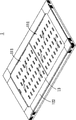
Fig. 1 is the three-dimensional exploded view of the utility model illumination lamp panel one preferred embodiment;
Fig. 2 is the three-dimensional combination figure of the utility model illumination lamp panel one preferred embodiment;
Fig. 3 is the three-dimensional exploded view of another angle of lamp panel framework module of the utility model illumination lamp panel; And
Fig. 4 is the stereo appearance figure of another preferred embodiment of the utility model illumination lamp panel.
Reference numeral lists as follows:
The 1-lamp panel that throws light on
11-wick heat radiation module
The 111-heat sink
The 112-light-emittingdiode
The 113-power supply changeover device
The 114-power connector
12-lamp panel framework module
The 121-Connection Block
The 122-connecting frame
The 123-conduit
13-optics diffusion panel
The specific embodiment
Below by particular specific embodiment embodiment of the present utility model is described, be familiar with that the those skilled in the art of technical field can understand other advantage of the present utility model and effect easily by the content that this specification disclosed under the utility model.
The graphic explanation of following reference embodiment of the present utility model, it should be noted, below graphic for the signal of simplifying graphic, and basic conception of the present utility model only is described in a schematic way, so only the illustration structure relevant with the utility model but not component number, shape and size when implementing according to reality are drawn in graphic, form, quantity and the ratio of each element are not to exceed with diagram during its actual implements, and can need change according to actual design, close chat earlier bright.
At first, see also Fig. 1, Fig. 2 and shown in Figure 3, be the three-dimensional exploded view of three-dimensional exploded view, three-dimensional combination figure and another angle of lamp panel framework module of a preferred embodiment of the utility model illumination lamp panel.As shown in the figure, illumination lamp panel 1 of the present utility model includes wick heat radiation module 11, a lamp panel framework module 12 and at least one optics diffusion panel 13.
Wick heat radiation module 11 has a heat sink 111, is located at plural light-emittingdiode 112, plural power supply changeover device 113 and at least one power connector 114 on heat sink 111 surfaces.In the present embodiment, heat sink 111 is a foursquare heat sink 111, and light-emittingdiode 112 is rectangle and the surface that is arranged at heat sink 111 in the mode that matrix is arranged.Power-supply adapter 113 is an AC-DC converter 113, and is arranged on the heat sink 111, and is positioned at the outside of plural light-emittingdiode 112, makes plural light-emittingdiode 112 can see through AC-DC converter 113 and carries out the conversion of alterating and direct current.Power connector 114 is in order to connecting external power source, to provide plural light-emittingdiode 112 required power supply.
Lamp panel framework module 12 has plural Connection Block 121 and is assembled in plural connecting frame 122 on the plural Connection Block 121, Connection Block 121 correspondences are arranged on the corner of heat sink 111, the two ends of connecting frame 122 are assembled on the different Connection Block 121, constitute a framework with this, heat sink 111 can be fixed in the lamp panel framework module 12.And connecting frame 122 has a conduit 123, and this conduit 123 provides optics diffusion panel 13 to be embedded in it.In the present embodiment, connecting frame 122 is the light steelframe of aluminium extruded type, makes overall appearance more attractive in appearance, but not as limit, in other embodiments, connecting frame 122 also can be other structure and constitutes.
When assembling, plural Connection Block 121 and plural connecting frame 122 are assembled into a frame type mutually, optics is spread panel 13 again and be embedded in the conduit 123, the module 11 that again wick dispelled the heat at last is locked on the lamp panel framework module 12, can finish assembling easily fast.By this, when the single element (for example power supply changeover device 113) of wick heat radiation module 11 inside damages, can take the element that maintain and replace damages fast apart, change and need not to put in order to organize to eliminate, so can reduce the effect that use cost has more environmental protection and energy saving.
Moreover the size of the corresponding general ceiling of the size of illumination lamp panel 1 of the present utility model is used so can be installed in general ceiling, uses so that different form such as ceiling type and suspension type to be provided.
Please consult shown in Figure 4 again, stereo appearance figure for another preferred embodiment of the utility model illumination lamp panel, as shown in the figure, illumination lamp panel 1 of the present utility model also can have two heat sinks 111, two heat sinks 111 are spaced setting, the length lengthening of connecting frame 122 is provided with, length with corresponding two heat sinks 111, same, the length of also relative two heat sinks 111 of length of optics diffusion panel 13 and elongated, make the size that strengthens illumination lamp panel 1, and then more large tracts of land and the more illuminating effect of high brightness can be provided.Like this then use applicable to the bigger interior space.More specifically, illumination lamp panel 1 visual different demands of the present utility model and the quantity of heat sink 111 of increasing, and then strengthen the volume that illuminating lamp is checked and regulated body, so that more large-area illuminating ray to be provided, have more practicality with order illumination lamp panel 1.
Compared to existing structure, illumination lamp panel of the present utility model is provided with plural light-emittingdiode at least one heat sink, to utilize the characteristic of light-emittingdiode itself, reach effects such as life-span length, high brightness, energy-conservation, power saving and environmental protection, and the setting that can see through heat sink produces overheated phenomenon to avoid plural light-emittingdiode.In addition, when the single spare part on the wick heat radiation module damages, only need to change an element that damages and get final product, change and need not whole illumination lamp panel eliminated, so can avoid waste.And, if strengthening the size of illumination lamp panel, desire only need set up several heat sinks, can increase the size of illumination lamp panel, can promote field of illumination and scope relatively, thus can do different designs or adjustment in response to different occasions or space, to promote whole practicality.Moreover the also visual different demands of color of optics diffusion panel adjust, and then can produce the illuminating ray of different colours, the variability when using to increase.
Though aforesaid description and graphicly disclosed the utility model preferred embodiment, but must recognize variously increase, many modifications and replace and may be used in the utility model preferred embodiment, can not break away from the spirit and the scope of the utility model principle that claim defines.The those skilled in the art that are familiar with the affiliated technical field of the utility model can know from experience, and the utility model can be used in the modification of many forms, structure, layout, ratio, material, element and assembly.Therefore, this paper should be regarded as in order to explanation the utility model in the embodiment that this disclosed, but not in order to restriction the utility model.Scope of the present utility model should be defined by claim, and contains its legal equivalents, is not limited to previous description.
Claims (10)
- One kind the illumination lamp panel, it is characterized in that comprising:One wick heat radiation module has a heat sink, is located at the plural light-emittingdiode on this heat sink surface, plural power supply changeover device and at least one power connector;One lamp panel framework module has plural Connection Block and is assembled in plural connecting frame on this plural number Connection Block, and this plural number Connection Block frame is located at the corner of this heat sink, and this plural number connection box frame-saw is located at each side of this heat sink; AndAt least one optics diffusion panel is assembled on this plural number connecting frame, is overlying on this heat sink surface with the correspondence cover.
- 2. illumination lamp panel as claimed in claim 1 is characterized in that this heat sink is square heat sink or rectangle heat sink.
- 3. illumination lamp panel as claimed in claim 2 is characterized in that this plural number light-emittingdiode is arranged at this heat sink surface with the matrix arrangement.
- 4. illumination lamp panel as claimed in claim 2 is characterized in that this Connection Block frame is located at four edges of this heat sink.
- 5. illumination lamp panel as claimed in claim 2 is characterized in that this connecting frame is four and the corresponding four side that is arranged at this heat sink.
- 6. illumination lamp panel as claimed in claim 1 is characterized in that this power supply changeover device is an AC-DC converter.
- 7. illumination lamp panel as claimed in claim 1 is characterized in that this power connector connects external power source.
- 8. illumination lamp panel as claimed in claim 1 is characterized in that this connecting frame has a conduit, and the side that spreads panel for this optics wears.
- 9. illumination lamp panel as claimed in claim 1 is characterized in that this optics diffusion panel is a square or rectangular.
- 10. illumination lamp panel as claimed in claim 1 is characterized in that this connecting frame is the light steelframe of aluminium extruded type.
Priority Applications (1)
| Application Number | Priority Date | Filing Date | Title |
|---|---|---|---|
| CN2009202178268U CN201513783U (en) | 2009-09-30 | 2009-09-30 | Lighting lamp panel |
Applications Claiming Priority (1)
| Application Number | Priority Date | Filing Date | Title |
|---|---|---|---|
| CN2009202178268U CN201513783U (en) | 2009-09-30 | 2009-09-30 | Lighting lamp panel |
Publications (1)
| Publication Number | Publication Date |
|---|---|
| CN201513783U true CN201513783U (en) | 2010-06-23 |
Family
ID=42485193
Family Applications (1)
| Application Number | Title | Priority Date | Filing Date |
|---|---|---|---|
| CN2009202178268U Expired - Fee Related CN201513783U (en) | 2009-09-30 | 2009-09-30 | Lighting lamp panel |
Country Status (1)
| Country | Link |
|---|---|
| CN (1) | CN201513783U (en) |
Cited By (6)
| Publication number | Priority date | Publication date | Assignee | Title |
|---|---|---|---|---|
| WO2012158894A3 (en) * | 2011-05-17 | 2013-04-25 | Pixi Lighting Llc | Flat panel lighting device and driving circuitry |
| CN104344360A (en) * | 2013-08-07 | 2015-02-11 | 海洋王(东莞)照明科技有限公司 | Illumination lamp and transparent part pressing plate thereof |
| US9476552B2 (en) | 2013-04-17 | 2016-10-25 | Pixi Lighting, Inc. | LED light fixture and assembly method therefor |
| US9500328B2 (en) | 2013-04-17 | 2016-11-22 | Pixi Lighting, Inc. | Lighting assembly |
| US9546781B2 (en) | 2013-04-17 | 2017-01-17 | Ever Venture Solutions, Inc. | Field-serviceable flat panel lighting device |
| US9557022B2 (en) | 2015-04-30 | 2017-01-31 | Ever Venture Solutions, Inc. | Non-round retrofit recessed LED lighting fixture |
-
2009
- 2009-09-30 CN CN2009202178268U patent/CN201513783U/en not_active Expired - Fee Related
Cited By (23)
| Publication number | Priority date | Publication date | Assignee | Title |
|---|---|---|---|---|
| US9562678B2 (en) | 2011-05-17 | 2017-02-07 | Pixi Lighting, Inc. | Flat panel lighting device |
| US10422518B2 (en) | 2011-05-17 | 2019-09-24 | Unity Opto Technology Co., Ltd. | Flat panel lighting device |
| US10364974B2 (en) | 2011-05-17 | 2019-07-30 | Unity Opto Technology Co., Ltd. | Flat panel lighting device and driving circuitry |
| CN103562625A (en) * | 2011-05-17 | 2014-02-05 | 毕克斯照明有限责任公司 | Flat panel lighting device and driving circuitry |
| US9976732B2 (en) | 2011-05-17 | 2018-05-22 | Unity Opto Technology Co., Ltd. | Flat panel lighting device and driving circuitry |
| US9335036B2 (en) | 2011-05-17 | 2016-05-10 | Pixi Lighting, Inc. | Flat panel lighting device and driving circuitry |
| US9423113B2 (en) | 2011-05-17 | 2016-08-23 | Pixi Lighting, Inc. | Flat panel lighting device and driving circuitry |
| US9441801B1 (en) | 2011-05-17 | 2016-09-13 | Pixi Lighting, Inc. | Flat panel lighting device and driving circuitry |
| US9447954B2 (en) | 2011-05-17 | 2016-09-20 | Pixi Lighting, Inc. | Light fixture having a central wire-way |
| US9523487B1 (en) | 2011-05-17 | 2016-12-20 | Pixi Lighting, Inc. | Flat panel lighting device and driving circuitry |
| CN103534527A (en) * | 2011-05-17 | 2014-01-22 | 毕克斯照明有限责任公司 | Flat panel lighting device and retrofit kit |
| WO2012158908A3 (en) * | 2011-05-17 | 2013-04-25 | Pixi Lighting Llc | Flat panel lighting device and retrofit kit |
| US9453616B2 (en) | 2011-05-17 | 2016-09-27 | Pixi Lighting, Inc. | Flat panel lighting device |
| US9664365B2 (en) | 2011-05-17 | 2017-05-30 | Pixi Lighting, Inc. | Flat panel lighting device |
| WO2012158894A3 (en) * | 2011-05-17 | 2013-04-25 | Pixi Lighting Llc | Flat panel lighting device and driving circuitry |
| US9546781B2 (en) | 2013-04-17 | 2017-01-17 | Ever Venture Solutions, Inc. | Field-serviceable flat panel lighting device |
| US10215911B2 (en) | 2013-04-17 | 2019-02-26 | Unity Opto Technology Co., Ltd. | Lighting assembly |
| US10352544B2 (en) | 2013-04-17 | 2019-07-16 | Unity Opto Technology Co., Ltd. | Field-serviceable flat panel lighting device |
| US9476552B2 (en) | 2013-04-17 | 2016-10-25 | Pixi Lighting, Inc. | LED light fixture and assembly method therefor |
| US10386023B2 (en) | 2013-04-17 | 2019-08-20 | Unity Opto Technology Co., Ltd. | LED light fixture and assembly method therefor |
| US9500328B2 (en) | 2013-04-17 | 2016-11-22 | Pixi Lighting, Inc. | Lighting assembly |
| CN104344360A (en) * | 2013-08-07 | 2015-02-11 | 海洋王(东莞)照明科技有限公司 | Illumination lamp and transparent part pressing plate thereof |
| US9557022B2 (en) | 2015-04-30 | 2017-01-31 | Ever Venture Solutions, Inc. | Non-round retrofit recessed LED lighting fixture |
Similar Documents
| Publication | Publication Date | Title |
|---|---|---|
| CN101469844B (en) | Illuminating apparatus | |
| CN201513783U (en) | Lighting lamp panel | |
| CN201902885U (en) | Light emitting diode (LED) lamp bulb with high heat dissipation performance | |
| CN106247217A (en) | Use LED, module number can rubato flat lamp | |
| CN201069138Y (en) | Diversified function luminous diode lighting lamp | |
| CN102384386A (en) | Led lamp tube | |
| CN202992702U (en) | Optical module | |
| CN202327716U (en) | Light-emitting diode (LED) lamp tube | |
| CN202216031U (en) | Down right type light-emitting diode (LED) panel lamp | |
| CN201973485U (en) | LED illuminating lamp | |
| CN201836709U (en) | LED (light-emitting diode) daylight lamp with built-out power supply | |
| KR20130035385A (en) | The package type high power led lighting device | |
| CN202082756U (en) | Embedded led lamp panel | |
| CN201209791Y (en) | Embedded LED barrel lamp | |
| CN204062565U (en) | Integrated LED lamp | |
| CN103016977A (en) | Circuit board and wide-angle illumination LED lamp | |
| CN105508886A (en) | Integrated light source | |
| KR200468298Y1 (en) | Rembrandt Light and LED lights with reflective light | |
| CN203949074U (en) | Energy-saving LED area source Market Light | |
| CN203068206U (en) | Module type tube light | |
| RU2767167C1 (en) | Led module | |
| CN211011045U (en) | Diffuse reflection L ED panel lamp | |
| CN219414539U (en) | Lamp box for exhibition illumination | |
| CN209782558U (en) | Linear lighting lamp | |
| CN106764609B (en) | Multifunctional line type lamp convenient to install |
Legal Events
| Date | Code | Title | Description |
|---|---|---|---|
| C14 | Grant of patent or utility model | ||
| GR01 | Patent grant | ||
| C17 | Cessation of patent right | ||
| CF01 | Termination of patent right due to non-payment of annual fee |
Granted publication date: 20100623 Termination date: 20110930 |