CN202593603U - Cardan joint steering shaft - Google Patents
Cardan joint steering shaft Download PDFInfo
- Publication number
- CN202593603U CN202593603U CN 201220222622 CN201220222622U CN202593603U CN 202593603 U CN202593603 U CN 202593603U CN 201220222622 CN201220222622 CN 201220222622 CN 201220222622 U CN201220222622 U CN 201220222622U CN 202593603 U CN202593603 U CN 202593603U
- Authority
- CN
- China
- Prior art keywords
- raceway
- spherical shell
- ball cage
- joint steering
- steering shaft
- Prior art date
- Legal status (The legal status is an assumption and is not a legal conclusion. Google has not performed a legal analysis and makes no representation as to the accuracy of the status listed.)
- Expired - Fee Related
Links
Images


Abstract
The utility model discloses a cardan joint steering shaft. One end of a internal spline is connected with a steering column internal spline, and the other end of the cardan joint steering shaft is connected with a steering gear input shaft external spline through an internal spline. The cardan joint steering shaft structurally comprises a spherical shell and a sphere cage, wherein the spherical shell is in spherical surface fit with the sphere cage, a spherical shell connecting shaft is arranged on the outer side of the spherical shell, a sphere cage connecting shaft is arranged on the outer side of the sphere cage, a rolling path one is arranged on the inner surface of the spherical shell, a rolling path two is arranged on the outer surface of the sphere cage, the rolling path one is in close fit with the rolling path two, and a steel ball is arranged between the spherical shell and the sphere cage, is embedded in and rolls freely through the rolling path one and the rolling path two. When a driver drives a steering wheel to rotate, the spherical shell is driven by a transmission mechanism to rotate and then drives the sphere cage to rotate through the steel ball. When a certain included angle is formed between the spherical shell and the sphere cage, the steel ball passes through the rolling paths of the spherical shell and the sphere cage to automatically adjust the positions between the spherical shell and the sphere cage, and therefore constant-speed steering is achieved.
Description
Technical field
The utility model relates to a kind of structure of constant speed steering shaft, belongs to the steering shaft field, is specially the universal-joint steering shaft.
Background technology
Steering shaft is used for closure dish and deflector, in order to transmit the power or the moment of torsion of chaufeur.At present, the universal-joint steering shaft is often adopted in being connected between bearing circle and the deflector, and its structure is a double cruciform shaft; Adopt the steering shaft of this structure; True joint angle is big more, and the momentary angular speed of deflector, steering torque waveform are just inhomogeneous more, and then influence driver comfort.
The utility model content
The technical matters that the utility model will solve is to overcome existing defective, and purpose is to provide the cross groove universal joint steering shaft.
In order to solve the problems of the technologies described above, the utility model provides following technical scheme:
A kind of universal-joint steering shaft, its female splines is connected with the steering column female splines, and is connected with deflector input shaft male splines through female splines; It comprises spherical shell, the ball cage, and spherical shell cooperates with ball cage ball face; The spherical shell outside is provided with the spherical shell adapter shaft, and the ball cage outside is provided with ball cage adapter shaft, and the spherical shell inside face is provided with raceway one; Ball cage outside face is provided with raceway two, is provided with steel ball between spherical shell and the ball cage, and raceway one closely cooperates with raceway two; Steel ball is embedded in raceway one and the raceway two, freely rolls through raceway one and raceway two.
Further, said raceway one and said raceway two equal in length are corresponding each other.
Further, be provided with three identical steel balls between said spherical shell and the ball cage, spherical shell is provided with three identical raceways one, and the ball cage is provided with three identical raceways two, and every steel ball all is arranged in corresponding raceway one and raceway two.Said three steel balls are uniformly distributed between spherical shell and the ball cage.
Further, the cross section of said raceway one, said raceway two all is a semicircular structure, and the radius of each semicircle raceway equates with the radius of said steel ball.
Further; Said three raceways one string that formed arbitrary camber line two-end-point links to each other on spherical shell all is parallel to the central axis of spherical shell adapter shaft, and said three raceways two string that formed arbitrary camber line two-end-point links to each other on the ball cage all is parallel to the central axis of ball cage adapter shaft.
Further, evenly be provided with six steel balls between said spherical shell and the said ball cage, and the centre of sphere of six steel balls is positioned at same plane.
The cross section of said raceway one also can be the half elliptic structure, and the cross section of said raceway two also can be the half elliptic structure, and after raceway one was closely joined with raceway two, steel ball was embedded in two raceways and between two raceways and freely rolls.
When chaufeur driving direction dish rotates, drive spherical shell through transmission device and rotate, and, drive the ball cage and rotate through steel ball.When spherical shell and ball cage had certain angle, steel ball was through the raceway between spherical shell and the ball cage, the position of automatically regulating between them, thus realize that constant speed turns to.
The universal-joint steering shaft adopts the said structure setting, can reach the wider universal-joint straight angle, and universal-joint straight angle maximum can reach 90 °; Therefore; The universal-joint steering shaft can be implemented in any adjustment on all directions, and the fluctuation of transmitting torque or rotating speed is good, and driving efficiency is high.
Description of drawings
Accompanying drawing is used to provide the further understanding to the utility model, and constitutes the part of specification sheets, is used to explain the utility model with the embodiment of the utility model, does not constitute the restriction to the utility model.In the accompanying drawings:
Fig. 1 is the cross-sectional view of the utility model universal-joint steering shaft;
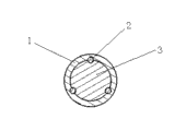
Fig. 2 be among the utility model embodiment one the universal-joint steering shaft along A-A direction schematic cross-section;
Fig. 3 be among the utility model embodiment two the universal-joint steering shaft along A-A direction schematic cross-section.
Among the figure, 1--spherical shell, 2--steel ball, 3--ball cage, 4--raceway one, 5--raceway two, 6-spherical shell adapter shaft, 7-ball cage adapter shaft.
The specific embodiment
Describe below in conjunction with the preferred embodiment of accompanying drawing, should be appreciated that preferred embodiment described herein only is used for explanation and explains the utility model, and be not used in qualification the utility model the utility model.
Embodiment one:
Like Fig. 1, shown in 2; A kind of universal-joint steering shaft comprises spherical shell 1, ball cage 3, spherical shell 1 and ball cage 3 for sphere cooperates, and spherical shell 1 outside is provided with spherical shell adapter shaft 6; Ball cage 3 outsides are provided with ball cage adapter shaft 7, are provided with three identical steel balls 2 between spherical shell 1 and the ball cage 3.Spherical shell 1 inside face is provided with the semicircle raceway 1 that equates with the radius of steel ball 2; Ball cage 3 outside faces are provided with semicircle raceway 25; Raceway 1 closely cooperates with raceway 25; Make three steel balls 2 in separately raceway 1 and raceway 25, freely to roll, and raceway 1 equate with raceway 25 length.
Three steel balls 2 are uniformly distributed between spherical shell 1 and the ball cage 3, equate with three steel balls, 2 corresponding three raceway one 4 length and the string of formed arbitrary camber line two-end-point on the spherical shell 1 all parallel, equate with three steel balls, 2 corresponding raceway 25 length with the central axis of spherical shell adapter shaft 6 and on ball cage 3 string of formed arbitrary camber line two-end-point all parallel with ball cage adapter shaft 7.
Angle between the axis of the ball cage adapter shaft 7 in the axis of the spherical shell adapter shaft 6 in spherical shell 1 outside and ball cage 3 outsides is 180 °; And when per three steel balls 2 all are positioned at the middle of corresponding raceway one (4), raceway two (5); The centre of sphere of three steel balls 2 is uniformly distributed between spherical shell 1 and the ball cage 3 and prolongs on the cross section of A-A direction; The center of circle in perpendicular and this cross section of the central axis of this cross section and spherical shell adapter shaft 6 and ball cage adapter shaft 7 is the center of ball cage 3 and spherical shell 1 just also; Each raceway semicircular in shape all on the cross section of prolonging the A-A direction, with the circumference tight connecting of steel ball together.
When chaufeur driving direction dish rotates, drive spherical shell through transmission device and rotate, and, drive the ball cage and rotate through steel ball.When spherical shell and ball cage had certain angle, steel ball was through the semicircle raceway of spherical shell and ball cage, the position of automatically regulating between them, thus the realization constant speed turns to.
Embodiment two:
As shown in Figure 3; The difference of present embodiment and embodiment one described universal-joint steering shaft is: be provided with six steel balls 2 between the spherical shell 1 of the universal-joint steering shaft in the present embodiment and the ball cage 3; Six and steel ball 2 corresponding raceways 1 are set on the spherical shell 1, six and steel ball 2 corresponding raceways 25 are set on the ball cage 3.
Six steel ball 2 centre ofs sphere are uniformly distributed in along on the cross section of A-A direction, and every raceway 1 equates with every raceway 25 length and along semicircular in shape all on the cross section of A-A direction, with the circumference tight connecting of steel ball together.
Embodiment three:
The difference of present embodiment and embodiment one described universal-joint steering shaft is: the cross-sectional plane of the raceway 1 in the universal-joint steering shaft in the present embodiment is the half elliptic structure, and the cross-sectional plane of raceway 25 is the half elliptic structure.
The above is merely the preferred embodiment of the utility model; Be not limited to the utility model; Although the utility model has been carried out detailed explanation with reference to previous embodiment; For a person skilled in the art, it still can be made amendment to the technical scheme that aforementioned each embodiment put down in writing, and perhaps part technical characterictic wherein is equal to replacement.All within the spirit and principle of the utility model, any modification of being done, be equal to replacement, improvement etc., all should be included within the protection domain of the utility model.
Claims (8)
1. a universal-joint steering shaft is characterized in that: comprise spherical shell (1), ball cage (3); Spherical shell (1) cooperates with ball cage (3) sphere, and the spherical shell outside is provided with spherical shell adapter shaft (6), and the ball cage outside is provided with ball cage adapter shaft (7); Spherical shell (1) inside face is provided with raceway one (4); Ball cage (3) outside face is provided with raceway two (5), is provided with steel ball (2) between spherical shell (1) and the ball cage (3), and raceway one (4) closely cooperates with raceway two (5); Steel ball (2) is embedded in raceway one (4) and the raceway two (5), freely rolls through raceway one (4) and raceway two (5).
2. universal-joint steering shaft according to claim 1 is characterized in that: said raceway one (4) and said raceway two (5) equal in length are corresponding each other.
3. universal-joint steering shaft according to claim 1; It is characterized in that: be provided with three identical steel balls (2) between said spherical shell (1) and the ball cage (3); Spherical shell (1) is provided with three identical raceways one (4); Ball cage (3) is provided with three identical raceways two (5), and every steel ball (2) all is arranged in corresponding raceway one (4) and raceway two (5).
4. universal-joint steering shaft according to claim 3 is characterized in that: said three steel balls are uniformly distributed between spherical shell (1) and the ball cage (3).
5. according to each described universal joint steering spindle of claim 1 to 4, it is characterized in that: the cross section of said raceway one (4), said raceway two (5) all is a semicircular structure, and the radius of each semicircle raceway equates with the radius of said steel ball (2).
6. according to claim 3 or 4 each described universal-joint steering shafts; It is characterized in that: said three raceways one (4) are gone up the central axis that the continuous string of formed arbitrary camber line two-end-point all is parallel to spherical shell adapter shaft (6) at spherical shell (1), and said three raceways two (5) are gone up the central axis that the continuous string of formed arbitrary camber line two-end-point all is parallel to ball cage adapter shaft (7) at ball cage (3).
7. universal-joint steering shaft according to claim 1 is characterized in that: evenly be provided with six steel balls between said spherical shell (1) and the said ball cage (3), and the centre of sphere of six steel balls is positioned at same plane.
8. universal-joint steering shaft according to claim 1; It is characterized in that: the cross section of said raceway one (4) is the half elliptic structure; The cross section of said raceway two (5) is the half elliptic structure; Raceway one (4) closely cooperates with raceway two (5), and steel ball (2) is embedded in two raceways and between two raceways and freely rolls.
Priority Applications (1)
| Application Number | Priority Date | Filing Date | Title |
|---|---|---|---|
| CN 201220222622 CN202593603U (en) | 2012-05-17 | 2012-05-17 | Cardan joint steering shaft |
Applications Claiming Priority (1)
| Application Number | Priority Date | Filing Date | Title |
|---|---|---|---|
| CN 201220222622 CN202593603U (en) | 2012-05-17 | 2012-05-17 | Cardan joint steering shaft |
Publications (1)
| Publication Number | Publication Date |
|---|---|
| CN202593603U true CN202593603U (en) | 2012-12-12 |
Family
ID=47311175
Family Applications (1)
| Application Number | Title | Priority Date | Filing Date |
|---|---|---|---|
| CN 201220222622 Expired - Fee Related CN202593603U (en) | 2012-05-17 | 2012-05-17 | Cardan joint steering shaft |
Country Status (1)
| Country | Link |
|---|---|
| CN (1) | CN202593603U (en) |
Cited By (1)
| Publication number | Priority date | Publication date | Assignee | Title |
|---|---|---|---|---|
| CN106913341A (en) * | 2017-03-22 | 2017-07-04 | 上海谦益生物科技有限公司 | A kind of wearable device, system and method for disturbances in patients with Parkinson disease gait training and monitoring and evaluation |
-
2012
- 2012-05-17 CN CN 201220222622 patent/CN202593603U/en not_active Expired - Fee Related
Cited By (1)
| Publication number | Priority date | Publication date | Assignee | Title |
|---|---|---|---|---|
| CN106913341A (en) * | 2017-03-22 | 2017-07-04 | 上海谦益生物科技有限公司 | A kind of wearable device, system and method for disturbances in patients with Parkinson disease gait training and monitoring and evaluation |
Similar Documents
| Publication | Publication Date | Title |
|---|---|---|
| CN103075440B (en) | Roller type bidirectional overrunning clutch | |
| CN202593603U (en) | Cardan joint steering shaft | |
| CN201461763U (en) | Universal joint transmission shaft assembly with combination of ball cage and four-ball pin | |
| CN103867590B (en) | Extension type ball-cage constant velocity universal saves | |
| CN110821978A (en) | Eight steel ball rzeppa constant velocity joints of wide-angle high efficiency | |
| WO2010127513A1 (en) | Constant velocity driving shaft assembly with large swing angle and large slide range | |
| CN211398335U (en) | Eight steel ball rzeppa constant velocity joints of wide-angle high efficiency | |
| CN102392858B (en) | Symmetrical ball roller path constant velocity cardan joint | |
| CN204210311U (en) | A kind of all-terrain vehicle drive axle and active conical tooth wheel transmission device thereof | |
| CN203641433U (en) | Differential mechanism with spur gears and universal joints | |
| CN105179499A (en) | Eight-steel-ball rzeppa constant velocity joint | |
| CN201461764U (en) | Universal joint transmission shaft assembly with combination of ball cage and joint bearing | |
| CN201475194U (en) | Novel universal transmission device | |
| CN204677629U (en) | Portable ball-cage constant velocity universal joint | |
| CN208804195U (en) | A kind of Universal drive gear structure | |
| CN208294973U (en) | A kind of combined three ball pin style constant speed universal joint of ball steel ball | |
| KR20130055832A (en) | Sliding ball type contant velocity joint for vehicle | |
| CN204025409U (en) | Improved constant-velocity transmission shaft | |
| CN203560322U (en) | Three-fork double-side steel ball type universal coupling with constant angular velocity | |
| CN204739199U (en) | Can bear herringbone tooth wheel set of additional axial force | |
| CN105840761B (en) | Can automatic speed regulation transmission device and its application method | |
| CN217170784U (en) | Connecting structure of intermediate shaft and steering column | |
| CN105276016A (en) | Multi-transmission universal joint | |
| CN103343784B (en) | Connection-rod-type constant velocity universal joint | |
| CN201593572U (en) | Double-spline structured input shaft inner ball cage |
Legal Events
| Date | Code | Title | Description |
|---|---|---|---|
| C14 | Grant of patent or utility model | ||
| GR01 | Patent grant | ||
| C17 | Cessation of patent right | ||
| CF01 | Termination of patent right due to non-payment of annual fee |
Granted publication date: 20121212 Termination date: 20140517 |