CN202566607U - Key ring - Google Patents
Key ring Download PDFInfo
- Publication number
- CN202566607U CN202566607U CN 201220131523 CN201220131523U CN202566607U CN 202566607 U CN202566607 U CN 202566607U CN 201220131523 CN201220131523 CN 201220131523 CN 201220131523 U CN201220131523 U CN 201220131523U CN 202566607 U CN202566607 U CN 202566607U
- Authority
- CN
- China
- Prior art keywords
- key
- key ring
- people
- ring
- entering ends
- Prior art date
- Legal status (The legal status is an assumption and is not a legal conclusion. Google has not performed a legal analysis and makes no representation as to the accuracy of the status listed.)
- Expired - Fee Related
Links
Images

Abstract
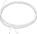
The utility model relates to a key ring, which comprises a body, wherein two key entering ends and a sandwich layer are arranged on the body, the sandwich layer is formed by bending and overlapping one metal wire, the key ring also comprises a convex element capable of tilting the key entering ends, the convex element is arranged on the body near the key entering ends, the body is in a spiral shape, the body and the convex element are made into a whole, and the spiral layers of the body are in three layers. The key ring provided by the utility model has the advantages that in the use process, people only need to downwards extrude the part near the convex element part but far away from the key entering ends, the convex element becomes the support point because of the lever principle effect, the key entering ends can be upwards tilted, people can pass a key hole through the entering ends to rotate around the sandwich layer, and the key is hung on the key ring. The key ring has the advantages that the operation is simple, the use is convenient, the upward pulling trouble of people trough extending the fingers into the key entering ends is avoided, and convenience is brought for people to hang the key on the key ring.
Description
Technical field
The utility model relates to a kind of haberdashery and hardware utensil, specifically is a kind of being used for a plurality of key chain key ring together.
Background technology
People go out and can carry key, for example: door key, car key, cupboard key and warehouse key etc.Because the key that carries is too much, people can use key ring with these key chain together basically, are easy to carry.The key ring of prior art is formed by stacking an one metal wire bending.When key is packed into key ring; Just need be pulled upwardly with the key upstream end of finger with key ring; Make the key upstream end perk of key ring, then hole is on the key passed the key upstream end of key ring, the winding direction motion around key ring at last makes key chain on key ring.Because the clamping force of key ring is bigger, can make people in the process of string key, finger can be crushed by key ring.Misoperation, even can cause the key upstream end of key ring to inject in the nail seam makes people injured, uses very inconvenient and brings unnecessary trouble to people.
Summary of the invention
The purpose of the utility model is to overcome deficiency of the prior art, and a kind of key ring is provided, be convenient to people with key chain on key ring and easy to use.
For solving the problems of the technologies described above; The key ring that the utility model provides comprises body; The interlayer that described body is provided with two key upstream ends and is formed by stacking an one metal wire bending; It also comprises can be with the male member of key upstream end perk, and described male member is arranged on the body near the key upstream end.
After adopting above structure, the utility model compared with prior art has the following advantages: the key ring that the utility model provides in use; As long as people will push downwards near the male member place and from a key upstream end place far away, because the effect of lever principle, male member is the strong point; Will make the key upstream end be upturned; Thereby people pass the key upstream end with the hole of key, curl up along interlayer, make key chain on key ring.The utility model key ring is simple to operate, and is easy to use, removes people from the trouble that finger is pulled upwardly the key upstream end, be convenient to people with key chain on key ring.
As preferably, described body is a spirality.
As preferably, described body and male member are one.
As improvement, the spiral layers of described body has three layers.The key ring of this structure twines three circles by an one metal wire and forms, and makes this physical efficiency play a supporting role to male member, is convenient to the string key that people can be convenient.
Description of drawings
Fig. 1 is the structural representation of the utility model key ring.
Fig. 2 is that the A of Fig. 1 is to view.
Wherein: 1, body; 2, male member.
The specific embodiment
As depicted in figs. 1 and 2; A kind of key ring comprises body 1, the interlayer that described body 1 is provided with two key upstream ends and is formed by stacking an one metal wire bending; It also comprises can be with the male member 2 of key upstream end perk, and described male member 2 is arranged on the body 1 near the key upstream end.
Described body 1 is a spirality.
Described body 1 is one with male member 2.
The spiral layers of described body 1 has three layers.
Claims (4)
1. key ring; Comprise body (1); The interlayer that described body (1) is provided with two key upstream ends and is formed by stacking an one metal wire bending; It is characterized in that: it also comprises can be with the male member (2) of key upstream end perk, and described male member (2) is arranged on the body (1) near the key upstream end.
2. key ring according to claim 1 is characterized in that: described body (1) is a spirality.
3. key ring according to claim 1 is characterized in that: described body (1) and male member (2) are one.
4. key ring according to claim 1 and 2 is characterized in that: the spiral layers of described body (1) has three layers.
Priority Applications (1)
| Application Number | Priority Date | Filing Date | Title |
|---|---|---|---|
| CN 201220131523 CN202566607U (en) | 2012-03-30 | 2012-03-30 | Key ring |
Applications Claiming Priority (1)
| Application Number | Priority Date | Filing Date | Title |
|---|---|---|---|
| CN 201220131523 CN202566607U (en) | 2012-03-30 | 2012-03-30 | Key ring |
Publications (1)
| Publication Number | Publication Date |
|---|---|
| CN202566607U true CN202566607U (en) | 2012-12-05 |
Family
ID=47236088
Family Applications (1)
| Application Number | Title | Priority Date | Filing Date |
|---|---|---|---|
| CN 201220131523 Expired - Fee Related CN202566607U (en) | 2012-03-30 | 2012-03-30 | Key ring |
Country Status (1)
| Country | Link |
|---|---|
| CN (1) | CN202566607U (en) |
Cited By (2)
| Publication number | Priority date | Publication date | Assignee | Title |
|---|---|---|---|---|
| EP2552272A1 (en) * | 2010-03-29 | 2013-02-06 | Drosselmeyer Designgroup Aktiebolag | Key ring with compressible gap |
| CN103653558A (en) * | 2013-12-07 | 2014-03-26 | 宋晓玲 | Labor-saving key ring |
-
2012
- 2012-03-30 CN CN 201220131523 patent/CN202566607U/en not_active Expired - Fee Related
Cited By (3)
| Publication number | Priority date | Publication date | Assignee | Title |
|---|---|---|---|---|
| EP2552272A1 (en) * | 2010-03-29 | 2013-02-06 | Drosselmeyer Designgroup Aktiebolag | Key ring with compressible gap |
| EP2552272A4 (en) * | 2010-03-29 | 2014-03-19 | Drosselmeyer Designgroup Aktiebolag | Key ring with compressible gap |
| CN103653558A (en) * | 2013-12-07 | 2014-03-26 | 宋晓玲 | Labor-saving key ring |
Similar Documents
| Publication | Publication Date | Title |
|---|---|---|
| USD810008S1 (en) | Rooftop support block | |
| USD660690S1 (en) | Clip | |
| USD754416S1 (en) | Shaped tortilla | |
| USD718866S1 (en) | Heart rate belt | |
| USD645692S1 (en) | Cushion | |
| USD645690S1 (en) | Cushion | |
| USD645686S1 (en) | Cushion | |
| USD683920S1 (en) | Container device including contoured finger grips | |
| USD664838S1 (en) | Tubing clip | |
| USD645687S1 (en) | Cushion | |
| USD698187S1 (en) | Yoga mat | |
| CN202566607U (en) | Key ring | |
| USD738662S1 (en) | Pull strap for a recliner mechanism | |
| CN201507234U (en) | One-way extension ladder | |
| CN205756874U (en) | A kind of for fixing roasting cylinder assembly | |
| CN202312759U (en) | Sucking disc type hook row | |
| CN204780739U (en) | Multi -purpose telescopic link | |
| CN203058784U (en) | Folding conference table | |
| CN204022074U (en) | Convenient adhesive-tape cutter | |
| CN203064619U (en) | Gas jar mover | |
| CN203052977U (en) | Multifunctional electric heating fan | |
| CN203175059U (en) | Double-hollow-square-shaped hook | |
| CN202456778U (en) | Key ring | |
| USD644894S1 (en) | Shellfish cracking utensil | |
| CN103169340A (en) | Portable foldable tableware |
Legal Events
| Date | Code | Title | Description |
|---|---|---|---|
| C14 | Grant of patent or utility model | ||
| GR01 | Patent grant | ||
| C17 | Cessation of patent right | ||
| CF01 | Termination of patent right due to non-payment of annual fee |
Granted publication date: 20121205 Termination date: 20130330 |