CN202561663U - A LED lamp power supply installation structure - Google Patents
A LED lamp power supply installation structure Download PDFInfo
- Publication number
- CN202561663U CN202561663U CN 201120349677 CN201120349677U CN202561663U CN 202561663 U CN202561663 U CN 202561663U CN 201120349677 CN201120349677 CN 201120349677 CN 201120349677 U CN201120349677 U CN 201120349677U CN 202561663 U CN202561663 U CN 202561663U
- Authority
- CN
- China
- Prior art keywords
- slot
- power supply
- shape
- inverted
- installation structure
- Prior art date
- Legal status (The legal status is an assumption and is not a legal conclusion. Google has not performed a legal analysis and makes no representation as to the accuracy of the status listed.)
- Expired - Fee Related
Links
- 238000009434 installation Methods 0.000 title claims description 29
- 241001465382 Physalis alkekengi Species 0.000 abstract 1
- 238000010586 diagram Methods 0.000 description 5
- XAGFODPZIPBFFR-UHFFFAOYSA-N aluminium Chemical compound [Al] XAGFODPZIPBFFR-UHFFFAOYSA-N 0.000 description 2
- 229910052782 aluminium Inorganic materials 0.000 description 2
- 238000000034 method Methods 0.000 description 2
- 239000000758 substrate Substances 0.000 description 2
- 230000000712 assembly Effects 0.000 description 1
- 238000000429 assembly Methods 0.000 description 1
- 238000012423 maintenance Methods 0.000 description 1
Images


Landscapes
- Non-Portable Lighting Devices Or Systems Thereof (AREA)
- Fastening Of Light Sources Or Lamp Holders (AREA)
Abstract
Description
技术领域 technical field
本发明涉及照明技术,尤其涉及一种LED灯具电源安装结构。 The invention relates to lighting technology, in particular to a power supply installation structure for LED lamps. the
背景技术 Background technique
LED灯具有寿命长、省电力的特点,越来越广泛地应用于照明领域。LED灯具尤其是大功率LED照明灯具,一般均单独配置一电源,电源的寿命小于LED灯具,是故障率较高的部件。 LED lights have the characteristics of long life and power saving, and are more and more widely used in the field of lighting. LED lamps, especially high-power LED lighting lamps, are generally equipped with a separate power supply. The life of the power supply is shorter than that of LED lamps, and it is a component with a high failure rate. the
中国专利文献CN201772370U于2011年3月23日公开了一种LED路灯,包括灯头组件(1)、灯头纵梁(2)、框形灯架(3)、灯架横梁(4)及驱动电源(7),在所述灯头纵梁(2)的底面上设有数个所述灯头组件(1),一条或一条以上的灯头纵梁(2)平行设置在所述灯架横梁(4)上,所述灯头纵梁(2)和灯架横梁(4)安装在所述框形灯架(3)内,所述驱动电源(7)设置在所述框形灯架(3)上;所述灯头组件(1)包括透镜(11)、橡胶圈(12)、LED芯片(13)、铝基板(14)、灯头体(16)和橡胶柱(17),所述透镜(11)、橡胶圈(12)、LED芯片(13)、铝基板(14)、灯头体(16)和橡胶柱(17)从下至上依次压合为一体。该专利文献中,驱动电源通过上盖及下盖锁定在框形灯架上,给拆装带来不便。 Chinese patent document CN201772370U discloses a kind of LED street lamp on March 23, 2011, comprises lamp cap assembly (1), lamp cap stringer (2), frame-shaped lamp frame (3), lamp frame beam (4) and drive power supply ( 7), several lamp cap assemblies (1) are arranged on the bottom surface of the lamp cap longitudinal beam (2), and one or more lamp cap longitudinal beams (2) are arranged in parallel on the lamp frame beam (4), The lamp holder longitudinal beam (2) and the lamp frame beam (4) are installed in the frame-shaped lamp frame (3), and the driving power supply (7) is arranged on the frame-shaped lamp frame (3); Lamp assembly (1) comprises lens (11), rubber ring (12), LED chip (13), aluminum substrate (14), lamp head body (16) and rubber post (17), and described lens (11), rubber ring (12), the LED chip (13), the aluminum substrate (14), the lamp head body (16) and the rubber post (17) are pressed together sequentially from bottom to top. In this patent document, the driving power is locked on the frame-shaped light frame through the upper cover and the lower cover, which brings inconvenience to disassembly. the
和上述专利文献一样,现有技术中,LED灯具的电源一般通过螺丝钉锁定在灯体内,当电源出现故障时再松开紧固件,取下电源进行维修。LED灯具,尤其是路灯等高空照明灯具,实施取下和装上操作要在高空使用专门的工具进行作业,多有不便。 Like the above-mentioned patent documents, in the prior art, the power supply of LED lamps is generally locked in the lamp body by screws, and when the power supply fails, the fastener is loosened and the power supply is removed for maintenance. For LED lamps, especially high-altitude lighting fixtures such as street lamps, it is inconvenient to use special tools at high altitudes to perform removal and installation operations. the
发明内容 Contents of the invention
本发明的目的在于克服上述现有技术的不足之处而提供一种操作方便的LED灯具电源安装结构。 The object of the present invention is to overcome the disadvantages of the above-mentioned prior art and provide a power supply installation structure for LED lamps which is easy to operate. the
本发明的目的可以通过以下技术方案实现: The purpose of the present invention can be achieved through the following technical solutions:
一种LED灯具电源安装结构,包括电源,其特征在于:所述电源呈长条状,电源底部两端分别具有一块插板;该电源安装结构还包括与所述两块插板相对应的第一插槽和第二插槽,其中所述第一插槽固定地连接于被安装面,所述第二插槽弹性地连接于被安装面,所述被安装面指用于安装所述电源的表面。 A power supply installation structure for LED lamps, including a power supply, characterized in that: the power supply is in the shape of a strip, and two ends of the bottom of the power supply respectively have a plugboard; the power supply installation structure also includes a second plugboard corresponding to the two plugboards A slot and a second slot, wherein the first slot is fixedly connected to the installed surface, the second slot is elastically connected to the installed surface, and the installed surface is used for installing the power supply s surface.
LED灯具电源安装结构,其特征在于:所述第一插槽由一块压片、设置于该压片下表面的两条侧壁、一条后壁及被安装面共同界定而成,所述压片通过紧固件固定连接于被安装面。 The LED lamp power supply installation structure is characterized in that: the first slot is jointly defined by a pressing piece, two side walls arranged on the lower surface of the pressing piece, a rear wall and the surface to be installed, the pressing piece It is fixedly connected to the surface to be installed by fasteners. the
LED灯具电源安装结构,其特征在于:所述第二插槽由设置于一块弹片一端的下表面、该下表面的两条侧壁、一条后壁及被安装面共同界定而成,所述弹片另一端通过紧固件固定连接于被安装面。 The LED lamp power supply installation structure is characterized in that: the second slot is defined by the lower surface of one end of a shrapnel, two side walls of the lower surface, a rear wall and the surface to be installed, and the shrapnel The other end is fixedly connected to the surface to be installed by a fastener. the
LED灯具电源安装结构,其特征在于:所述弹片呈倒置的U形,所述第二插槽设置于倒置U形的一端,第二插槽的槽开口朝外,向U形内部延伸,所述倒置U形的另一端具有一水平向U形外部延伸的连接片,所述紧固件将连接片压设于被安装面。 The LED lamp power supply installation structure is characterized in that: the shrapnel is an inverted U-shape, the second slot is arranged at one end of the inverted U-shape, and the slot opening of the second slot faces outward and extends toward the inside of the U-shape, so The other end of the inverted U-shape has a connecting piece extending horizontally to the outside of the U-shape, and the fastener presses the connecting piece on the surface to be installed. the
LED灯具电源安装结构,其特征在于:所述第一插槽由设置于一块压片下表面的两条侧壁、一条后壁及被安装面共同界定而成,所述压片通过紧固件固定连接于被安装面;所述第二插槽由设置于一块弹片一端的下表面的两条侧壁、一条后壁及被安装面共同界定而成,所述弹片另一端通过紧固件固定连接于被安装面;所述弹片呈倒置的U形,所述第二插槽设置于倒置U形的一端,第二插槽的槽开口朝外,向U形内部延伸,所述倒置U形的另一端具有一水平向U形外部延伸的连接片,所述紧固件将连接片压设于被安装面;所述第一插槽之槽开口与所述第二插槽之槽开口相向设置。 The LED lamp power supply installation structure is characterized in that: the first slot is jointly defined by two side walls, a rear wall and the surface to be installed on the lower surface of a pressing piece, and the pressing piece is passed through a fastener Fixedly connected to the surface to be installed; the second slot is defined by two side walls, a rear wall and the surface to be installed on the lower surface of one end of a shrapnel, and the other end of the shrapnel is fixed by a fastener Connected to the surface to be installed; the shrapnel is an inverted U-shape, the second slot is set at one end of the inverted U-shape, the opening of the second slot is outward, and extends toward the inside of the U-shape, and the inverted U-shape The other end has a connecting piece extending horizontally to the outside of the U shape, and the fastener presses the connecting piece on the surface to be installed; the slot opening of the first slot is opposite to the slot opening of the second slot set up. the
LED灯具电源安装结构,其特征在于:所述电源处于安装状态时,电源两块插板外端部弹性地抵接于第一插槽后壁与第二插槽后壁之间。 The LED lamp power supply installation structure is characterized in that: when the power supply is in the installed state, the outer ends of the two plugboards of the power supply elastically abut between the rear wall of the first slot and the rear wall of the second slot. the
LED灯具电源安装结构,其特征在于:所述第二插槽向倒置U形内部移动的最大行程,大于所述第一插槽的深度。 The LED lamp power supply installation structure is characterized in that: the maximum stroke of the second slot moving to the inside of the inverted U shape is greater than the depth of the first slot. the
LED灯具电源安装结构,其特征在于:所述弹片之倒置U形的顶部具有由上向下延伸的过线槽。 The power supply installation structure for LED lamps is characterized in that: the top of the inverted U-shape of the shrapnel has a wire slot extending from top to bottom. the
LED灯具电源安装结构,其特征在于:所述被安装面是LED路灯、或LED隧道灯、或LED日光灯的灯体。 The LED lamp power installation structure is characterized in that: the surface to be installed is the lamp body of an LED street lamp, an LED tunnel lamp, or an LED fluorescent lamp. the
LED灯具电源安装结构,其特征在于:所述第一插槽由设置于一块压片下表面的两条侧壁、一条后壁及被安装面共同界定而成,所述压片通过紧固件固定连接于被安装面;所述第二插槽由设置于一块弹片一端的下表面的两条侧壁、一条后壁及被安装面共同界定而成,所述弹片另一端通过紧固件固定连接于被安装面;所述弹片呈倒置的U形,所述第二插槽设置于倒置U形的一端,第二插槽的槽开口朝外,向U形内部延伸,所述倒置U形的另一端具有一水平向U形外部延伸的连接片,所述紧固件将连接片压设于被安装面;所述第一插槽之槽开口与所述第二插槽之槽开口相向设置;所述电源处于安装状态时,电源两块插板外端部弹性地抵接于第一插槽后壁与第二插槽后壁之间;所述第二插槽向倒置U形内部移动的最大行程,大于所述第一插槽的深度;所述弹片之倒置U形的顶部具有由上向下延伸的过线槽;所述被安装面是LED灯具的灯体。 The LED lamp power supply installation structure is characterized in that: the first slot is jointly defined by two side walls, a rear wall and the surface to be installed on the lower surface of a pressing piece, and the pressing piece is passed through a fastener Fixedly connected to the surface to be installed; the second slot is defined by two side walls, a rear wall and the surface to be installed on the lower surface of one end of a shrapnel, and the other end of the shrapnel is fixed by a fastener Connected to the surface to be installed; the shrapnel is an inverted U-shape, the second slot is set at one end of the inverted U-shape, the opening of the second slot is outward, and extends toward the inside of the U-shape, and the inverted U-shape The other end has a connecting piece extending horizontally to the outside of the U shape, and the fastener presses the connecting piece on the surface to be installed; the slot opening of the first slot is opposite to the slot opening of the second slot Setting; when the power supply is in the installed state, the outer ends of the two plugboards of the power supply elastically abut between the rear wall of the first slot and the rear wall of the second slot; the second slot faces the inverted U-shaped interior The maximum stroke of movement is greater than the depth of the first slot; the inverted U-shaped top of the shrapnel has a wire slot extending from top to bottom; the surface to be installed is the lamp body of the LED lamp. the
本发明的LED灯具电源安装结构,包括与所述两块插板相对应的第一插槽和第二插槽,其中所述第一插槽固定地连接于被安装面,所述第二插槽弹性地连接于被安装面。拆装电源时,只需克服第二插槽的弹力即可快速操作,与现有技术相比,具有操作方便,不需要专门工具的优点。 The LED lamp power supply installation structure of the present invention includes a first slot and a second slot corresponding to the two plug boards, wherein the first slot is fixedly connected to the surface to be installed, and the second plug The slot is elastically connected to the mounted surface. When the power supply is disassembled, it can be quickly operated only by overcoming the elastic force of the second slot. Compared with the prior art, it has the advantages of convenient operation and no need for special tools. the
附图说明 Description of drawings
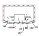
图1是本发明第一个实施例的示意图。 Fig. 1 is a schematic diagram of a first embodiment of the present invention. the
图2是本发明第一个实施例电源的示意图。 Fig. 2 is a schematic diagram of the power supply of the first embodiment of the present invention. the
图3是本发明第一个实施例第一插槽的示意图。 Fig. 3 is a schematic diagram of the first slot of the first embodiment of the present invention. the
图4是本发明第一个实施例第二插槽的示意图。 Fig. 4 is a schematic diagram of a second slot in the first embodiment of the present invention. the
图5是本发明第一个实施例安装电源的示意图。 Fig. 5 is a schematic diagram of installing a power supply according to the first embodiment of the present invention. the
具体实施方式 Detailed ways
下面将结合附图对本发明作进一步详述。 The present invention will be described in further detail below in conjunction with the accompanying drawings. the
参考图1-5,是本发明第一个实施例是一种LED灯具电源安装结构,包括电源101,所述电源101呈长条状,电源101底部两端分别具有一块插板102/103;该电源安装结构还包括与所述两块插板102/103相对应的第一插槽104和第二插槽105,其中所述第一插槽104固定地连接于被安装面115,所述第二插槽105弹性地连接于被安装面115,所述被安装面115指用于安装所述电源101的表面,本实施例中指LED路灯灯体,应当理解,被安装面115也可以是LED隧道灯、或LED日光灯的灯体。
Referring to Figures 1-5, the first embodiment of the present invention is a power supply installation structure for LED lamps, including a
本实施例中,所述第一插槽104由一块压片109、设置于该压片109下表面的两条侧壁108、一条后壁107及被安装面115共同界定而成,所述压片109通过紧固件固定连接于被安装面115。所述第二插槽105由设置于一块弹片112一端的下表面114、该下表面114的两条侧壁111、一条后壁110及被安装面115共同界定而成,所述弹片112另一端通过紧固件固定连接于被安装面115。本实施例中,所述弹片112呈倒置的U形,所述第二插槽105设置于倒置U形的一端,第二插槽105的槽开口朝外,向U形内部延伸,所述倒置U形的另一端具有一水平向U形外部延伸的连接片116,所述紧固件将连接片116压设于被安装面115。所述第一插槽之槽104开口与所述第二插槽之槽105开口相向设置。所述电源101处于安装状态时,电源两块插板102/103外端部弹性地抵接于第一插槽后壁107与第二插槽后壁110之间。
In this embodiment, the
为保证插拔的顺利,所述第二插槽105向倒置U形内部移动的最大行程,大于所述第一插槽104的深度。本实施例中,所述弹片112之倒置U形的顶部具有由上向下延伸的过线槽113。
In order to ensure smooth plugging and unplugging, the maximum stroke of the
安装电源101时,先将插板102插入第一插槽104,再将插板103由弹片112的上端克服弹力而向下推压,直至插板103插入第二插槽105。取出电源时,先将电源101向第二插内槽推压,弹片112变形,插板103向第二插槽105内部移动,并从第一插槽104内取出插板102,从而取出电源101。整个操作过程即方便,又不需要专门的工具。
When installing the
Claims (10)
Priority Applications (1)
| Application Number | Priority Date | Filing Date | Title |
|---|---|---|---|
| CN 201120349677 CN202561663U (en) | 2011-09-19 | 2011-09-19 | A LED lamp power supply installation structure |
Applications Claiming Priority (1)
| Application Number | Priority Date | Filing Date | Title |
|---|---|---|---|
| CN 201120349677 CN202561663U (en) | 2011-09-19 | 2011-09-19 | A LED lamp power supply installation structure |
Publications (1)
| Publication Number | Publication Date |
|---|---|
| CN202561663U true CN202561663U (en) | 2012-11-28 |
Family
ID=47211316
Family Applications (1)
| Application Number | Title | Priority Date | Filing Date |
|---|---|---|---|
| CN 201120349677 Expired - Fee Related CN202561663U (en) | 2011-09-19 | 2011-09-19 | A LED lamp power supply installation structure |
Country Status (1)
| Country | Link |
|---|---|
| CN (1) | CN202561663U (en) |
Cited By (1)
| Publication number | Priority date | Publication date | Assignee | Title |
|---|---|---|---|---|
| CN105202498A (en) * | 2015-10-02 | 2015-12-30 | 浙江司贝宁照明电器有限公司 | Driving power source installing structure for novel LED factory lamp |
-
2011
- 2011-09-19 CN CN 201120349677 patent/CN202561663U/en not_active Expired - Fee Related
Cited By (2)
| Publication number | Priority date | Publication date | Assignee | Title |
|---|---|---|---|---|
| CN105202498A (en) * | 2015-10-02 | 2015-12-30 | 浙江司贝宁照明电器有限公司 | Driving power source installing structure for novel LED factory lamp |
| CN105202498B (en) * | 2015-10-02 | 2018-10-09 | 浙江司贝宁照明电器有限公司 | A kind of driving power mounting structure of New LED factory lamp |
Similar Documents
| Publication | Publication Date | Title |
|---|---|---|
| CN102865526B (en) | Light-emitting diode (LED) tri-proof lamp | |
| CN203628340U (en) | LED lamp tube adopting flexible lamp panel | |
| CN103939859A (en) | How to assemble LED lights | |
| CN207762650U (en) | track lamp | |
| CN202561663U (en) | A LED lamp power supply installation structure | |
| CN202884619U (en) | Light-emitting diode (LED) down light | |
| CN204328522U (en) | A kind of LED | |
| CN203656673U (en) | Buckle type waterproof light tube | |
| CN202302945U (en) | A spring-pull type LED linear lamp | |
| CN201983066U (en) | Single-tube light-emitting diode (LED) daylight lamp | |
| CN202403203U (en) | Installation fastener of light-emitting diode (LED) strip lamp | |
| CN202629799U (en) | High-power LED tunnel lamp | |
| CN201916817U (en) | A kind of LED downlight | |
| CN217082286U (en) | LED lighting device convenient to dismouting | |
| CN102330951B (en) | LED lamp power supply mounting structure | |
| CN218442118U (en) | Module connecting structure of LED illuminating lamp | |
| CN201954298U (en) | Led light source module | |
| CN205026542U (en) | Embedded light in rail vehicle guest room | |
| CN202082652U (en) | LED lamp used as illumination source | |
| CN203641922U (en) | LED (Light Emitting Diode) bulb lamp | |
| CN202521389U (en) | LED (light emitting diode) module street lamp with ventilator | |
| CN201636564U (en) | Fluorescent lamp with reflector | |
| CN202118828U (en) | profiles | |
| CN210601293U (en) | LED ceiling lamp of ceiling lamp underframe and applied this underframe | |
| CN209655177U (en) | A kind of combined lamp case structure |
Legal Events
| Date | Code | Title | Description |
|---|---|---|---|
| C14 | Grant of patent or utility model | ||
| GR01 | Patent grant | ||
| C17 | Cessation of patent right | ||
| CF01 | Termination of patent right due to non-payment of annual fee |
Granted publication date: 20121128 Termination date: 20130919 |