CN202540273U - Support for inclined stay bar - Google Patents
Support for inclined stay bar Download PDFInfo
- Publication number
- CN202540273U CN202540273U CN2012200497190U CN201220049719U CN202540273U CN 202540273 U CN202540273 U CN 202540273U CN 2012200497190 U CN2012200497190 U CN 2012200497190U CN 201220049719 U CN201220049719 U CN 201220049719U CN 202540273 U CN202540273 U CN 202540273U
- Authority
- CN
- China
- Prior art keywords
- end plates
- bar
- hound
- cross bar
- inclined stay
- Prior art date
- Legal status (The legal status is an assumption and is not a legal conclusion. Google has not performed a legal analysis and makes no representation as to the accuracy of the status listed.)
- Expired - Fee Related
Links
Images
Abstract
The utility model relates to a support for an inclined stay bar. The support comprises the inclined stay bar, a cross bar, a vertical bar and two end plates, wherein one end of the cross bar is vertically connected with one end of the vertical bar; the two end plates are arranged on the inner sides of the cross bar and the vertical bar respectively; the inclined stay bar is connected to the two end plates; the end plates are connected with the inner sides of the cross bar and the vertical bar respectively by bolts; distance between the two end plates and the joint of the cross bar and the vertical bar is the same; and the inclined stay bar is in welding connection with the two end plates. By the support, the manufacturing and installation accuracy of the inclined stay bar of a steel platform is ensured, the total construction period of on-site installation is shortened, and installation labor is saved.
Description
Technical field
The utility model relates to a kind of support, and hound is used support specifically.
Background technology
At present, there is following problem in steel platform hound making work: 1, steel platform hound physical dimension and symmetry are difficult to control; 2, the site error of steel platform hound end plate fixing hole is difficult to control; 3, adopt traditional manufacture craft setting-out on operating platform, number material, welding hound end plate, its angular error can not 100% satisfies on-the-spot installation requirement.There is crack in the faying face that might occur during on-the-spot the installation between hound end plate and platform bottom, column side.
Summary of the invention
The utility model is intended to overcome the defective of prior art, provides a kind of hound to use support, and is simple in structure, easy to use, and precision is high.
In order to solve the problems of the technologies described above, the utility model is achieved in that
A kind of hound is used support, comprises hound, it is characterized in that: also comprise cross bar, montant and two end plates, cross bar one end vertically is connected with montant one end, and two end plates is located at the inboard of cross bar and montant respectively, and hound connects two end plates.
Described hound is used support, it is characterized in that: two end plates is connected through bolt with the inboard of cross bar and montant respectively, and two end plates is equal to the distance of cross bar and montant junction.
Described hound is used support, it is characterized in that: hound and two end plates adopt and are welded to connect.
The beneficial effect of the utility model is: guaranteed making of steel platform hound and installation accuracy, shortened the field erected overall duration, saved manual work is installed.
Description of drawings
Below in conjunction with accompanying drawing and embodiment the utility model is done further to specify:
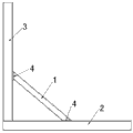
Fig. 1 is the structural representation of the utility model.
The specific embodiment
As shown in Figure 1: a kind of hound is used support, comprises hound 1, cross bar 2, montant 3 and two end plates 4, and cross bar 2 one ends vertically are connected with montant 3 one ends, and two end plates 4 is located at the inboard of cross bar 2 and montant 3 respectively, and hound 1 connects two end plates 4; Two end plates 4 is connected through bolt with the inboard of cross bar 2 with montant 3 respectively, and two end plates 4 is equal to the distance of cross bar 2 and montant 3 junctions; Hound 1 adopts with two end plates 4 and is welded to connect.The utility model has guaranteed making of steel platform hound and installation accuracy, has shortened the field erected overall duration, has saved manual work is installed.
Claims (3)
1. a hound is used support, comprises hound, it is characterized in that: also comprise cross bar, montant and two end plates, cross bar one end vertically is connected with montant one end, and two end plates is located at the inboard of cross bar and montant respectively, and hound connects two end plates.
2. hound according to claim 1 is used support, it is characterized in that: two end plates is connected through bolt with the inboard of cross bar and montant respectively, and two end plates is equal to the distance of cross bar and montant junction.
3. hound according to claim 1 is used support, it is characterized in that: hound and two end plates adopt and are welded to connect.
Priority Applications (1)
| Application Number | Priority Date | Filing Date | Title |
|---|---|---|---|
| CN2012200497190U CN202540273U (en) | 2012-02-16 | 2012-02-16 | Support for inclined stay bar |
Applications Claiming Priority (1)
| Application Number | Priority Date | Filing Date | Title |
|---|---|---|---|
| CN2012200497190U CN202540273U (en) | 2012-02-16 | 2012-02-16 | Support for inclined stay bar |
Publications (1)
| Publication Number | Publication Date |
|---|---|
| CN202540273U true CN202540273U (en) | 2012-11-21 |
Family
ID=47160957
Family Applications (1)
| Application Number | Title | Priority Date | Filing Date |
|---|---|---|---|
| CN2012200497190U Expired - Fee Related CN202540273U (en) | 2012-02-16 | 2012-02-16 | Support for inclined stay bar |
Country Status (1)
| Country | Link |
|---|---|
| CN (1) | CN202540273U (en) |
Cited By (2)
| Publication number | Priority date | Publication date | Assignee | Title |
|---|---|---|---|---|
| CN106826707A (en) * | 2017-02-13 | 2017-06-13 | 湖北工程职业学院 | The laborsaving operator of gun for coiling nail |
| CN107023744A (en) * | 2016-02-01 | 2017-08-08 | 五冶集团上海有限公司 | The gap processing method in technique steel construction hound two ends end plate connection face |
-
2012
- 2012-02-16 CN CN2012200497190U patent/CN202540273U/en not_active Expired - Fee Related
Cited By (2)
| Publication number | Priority date | Publication date | Assignee | Title |
|---|---|---|---|---|
| CN107023744A (en) * | 2016-02-01 | 2017-08-08 | 五冶集团上海有限公司 | The gap processing method in technique steel construction hound two ends end plate connection face |
| CN106826707A (en) * | 2017-02-13 | 2017-06-13 | 湖北工程职业学院 | The laborsaving operator of gun for coiling nail |
Similar Documents
| Publication | Publication Date | Title |
|---|---|---|
| CN203640309U (en) | Adjustable pipe carrier used on large-span steel structure roof primary truss general assembly jig frame | |
| CN103924674A (en) | High-strength bolt shear key structure and constructing method thereof | |
| CN203594213U (en) | Flexible assembling and disassembling bearing truss | |
| CN103362069B (en) | Steel and concrete combined box girder concrete wing plate formwork and construction method | |
| CN202627215U (en) | Major axis variable beam height assembling type node of H steel beam and H steel column | |
| CN203878753U (en) | High-strength bolt shear key structure | |
| CN202969589U (en) | H-type steel beam and rectangular steel tube column variable-beam depth assembly type node | |
| CN204282228U (en) | A kind of box steel arch beam Integral horizontal type group is to jig frame special | |
| CN202540273U (en) | Support for inclined stay bar | |
| CN202380401U (en) | Assembly jig frame of plate blocks of steel-truss-beam flexible-arch orthotropic bridge deck | |
| CN203475310U (en) | Formwork for concrete slabs of composite steel-concrete box girders | |
| CN204551936U (en) | A kind of steel external staircase | |
| CN103912080A (en) | Internal-reinforcement thin-wall steel composite wall suitable for quick assembly | |
| CN203330607U (en) | On-site butt joint connection and location device for construction steel structure box type section steel column | |
| CN203701386U (en) | Steel-structure floor slab group | |
| CN102864746A (en) | Bearing frame for bridge construction | |
| CN203145481U (en) | Manufacturing and positioning device of variable-angle steel pipe column splicing ear plate | |
| CN202627212U (en) | Steel structure joint assembly | |
| CN204139334U (en) | Girder steel and steel column weld temporary connecting structure entirely | |
| CN203247718U (en) | Steel column butt-joint mounting device | |
| CN204001941U (en) | The pillar of high-speed railway bridge contact net and guyed foundation assembly jig | |
| CN204171600U (en) | A kind of pillared location assembly-welding device | |
| CN203403576U (en) | Assembly-type parking lot floor plate of full steel structure | |
| CN202347665U (en) | Connection node constructional member of reinforced concrete beam and steel beam | |
| CN202726365U (en) | Connecting lug installing and welding device for rack section of derrick |
Legal Events
| Date | Code | Title | Description |
|---|---|---|---|
| C14 | Grant of patent or utility model | ||
| GR01 | Patent grant | ||
| C17 | Cessation of patent right | ||
| CF01 | Termination of patent right due to non-payment of annual fee |
Granted publication date: 20121121 Termination date: 20130216 |