CN202520976U - Non-rubber sealing valve - Google Patents
Non-rubber sealing valve Download PDFInfo
- Publication number
- CN202520976U CN202520976U CN2011205446523U CN201120544652U CN202520976U CN 202520976 U CN202520976 U CN 202520976U CN 2011205446523 U CN2011205446523 U CN 2011205446523U CN 201120544652 U CN201120544652 U CN 201120544652U CN 202520976 U CN202520976 U CN 202520976U
- Authority
- CN
- China
- Prior art keywords
- valve
- valve body
- valve seat
- sealing
- ring
- Prior art date
- Legal status (The legal status is an assumption and is not a legal conclusion. Google has not performed a legal analysis and makes no representation as to the accuracy of the status listed.)
- Expired - Fee Related
Links
Images


Abstract
A non-rubber sealing valve comprises a valve body part, a middle driving part and a sealing part, wherein the valve body part comprises a valve body, a valve cover, a holder, an indication nut, a valve seat and a laminated spring; the middle driving part comprises a power transmission component and a valve plate; the power transmission component comprises hand wheels and a valve rod; and the sealing part comprises an O-shaped ring, a mesoporous sealing ring, valve rod fillers, a sealing part of the valve seat, a sealing ring of the valve seat, and a gland for the fillers in the connection process of all parts. The sealing valve is characterized in that the sealing part of the valve seat, the sealing ring of the valve seat, and the mesoporous sealing ring are made of high-saturation acrylonitrile butadiene rubber, F4 carbon fibers and PEEK which have resistance to high/low temperature operating conditions, and the middle cavity of the valve body is designed into a mode that circles are formed at the upper and the lower parts, and a quadrate hole is formed in the middle part; the diameters of the upper and the lower circles are equal to the distance of diagonal lines of the quadrate hole; therefore, no large expansion or contraction is generated under high-temperature and high-pressure operating conditions, and the original operating performance of the valve is not affected. The original operating performance of the valve is better ensured so as to satisfy the condition that the valve can be used normally under the high/low temperature operating conditions.
Description
Technical field
The utility model belongs to valve and makes the field, relates to a kind of valve that under HTHP well head situation, uses, and is specifically related to a kind of no rubber seal valve.
Background technique
Valve extensively applies to be used for doing the connection pressure gauge in the industrial processes such as chemical industry, oil, metallurgy, mine, electric power, the energy, environmental protection, measures and government pressure; And as required, to the pipeline of fed sheet of a media discharging dirt, the valve in the existing techniques is because timely quick heat radiating; The protection filler improves working life, reduces bulk temperature; So that operation brings insecurity to production, particularly valve body is under high temperature or the low-temperature condition for a long time; Influence greatly validity, sealing and working life and the Safety performance of valve, and, in actual use; Operator because the HTHP situation of stop valve can not be accomplished timely alleviation, have increased operator's danger when operation.
Summary of the invention
The purpose of the utility model provides a kind of simple in structure; Long service life; Operation is easily reliable, and safety rate is high, and the Sealings such as highly saturated nitrile rubber, F4+ carbon fibre and PEEK of high-low temperature resistant operating mode are adopted in the sealing between valve body and valve seat, valve rod and the valve gap; Can satisfy valve normal use under high temperature and high pressure condition, satisfy the no rubber seal valve of the proper functioning of well head.
The purpose of the utility model is to realize through following technological scheme.
According to a kind of no rubber seal valve of the utility model, comprise valve body, valve base seal, valve seat insert, valve seat, folded spring, valve plate, guide plate, valve rod, mesopore seal ring, Stem Mut, valve gap, grease pouring valve, stem packing, hex head bolt, studding bolt, Gland, support, Cock screw, lubricating cup, thrust ring, bearing, dust ring, Cock screw, valve bonnet, indication nut, flat key, handwheel, hex head bolt, cover plate, lining, spacer ring, nameplate, rivet.It is characterized in that described high-low temperature resistant head valve is made up of valve body piece part, middle drive part and hermetic unit, valve body piece partly comprises valve body, valve gap, support, indication nut and valve seat and folded spring, and valve seat is embedded among the valve body; Folded spring is installed between valve seat and the valve body, is connected through bolt between valve gap and the valve body, is connected together through screw thread with support simultaneously; On the top of support the indication nut is installed, it plays indicative function to valve rod, and middle drive part comprises power transmitting assembly and valve plate; Power transmitting assembly is made up of handwheel, valve rod; Be connected through screw between handwheel and the valve rod, valve rod, is connected through leading screw between valve plate 6 and the valve rod in rack inner wall through bearings; The guide plate of valve plate cooperates with valve body and moves up and down; Hermetic unit is embodied in the connection procedure of each several part, comprises O type circle, mesopore seal ring, stem packing, valve base seal, valve seat insert and Gland, and valve base seal and valve seat insert are installed between valve body and the valve seat; The mesopore gasket ring is installed in valve body and valve gap assembling surface of contact, and stem packing and Gland are installed in the hollow space of valve gap and valve rod formation.
The described no rubber seal valve of the utility model, its valve base seal, valve seat insert and mesopore seal ring are all selected for use and are not contained the General Purpose Rubber material.
Further specify its characteristic, the utility model is designed to the middle square hole of circle up and down with the valve body lumen, and diameter of a circle equals the diagonal distance of square hole up and down, so that make valve seat press close to flashboard more, realizes reducing wear, and increases the sealability of flashboard and valve seat.And set up sealing at valve seat; Adopt and optimize the sealed groove design; It is material that described valve base seal, valve seat insert, mesopore seal ring all adopt high saturated NBR, F4+ carbon fibre and the PEEK of high-low temperature resistant operating mode, has overcome rubber parts and has had aging, perishable, the easy to wear weakness of being prone to.Under high worst cold case, do not produce bigger expansion or contraction, guarantee original service behaviour of valve preferably.Make the quick balance of valve pocket pressure, realize best sealability, have advantage such as reliable easy and safe to operate.Reduce the space that drift sand is invaded to the full extent, realize the safe and reliable use of valve.
A kind of usefulness of not having the rubber seal valve of the utility model is; Because under worst hot case; The expansion or the shrinkage coefficient of common sealing member material are much bigger than metallic material; The expansion or the contour projector of itself and metal seal, valve body counterpart are differed greatly, cause sealing to reduce and produce and to seal than serious.The Sealings such as highly saturated nitrile rubber, F4+ carbon fibre and PEEK of high-low temperature resistant operating mode are adopted in sealing between the utility model valve body and valve seat, valve rod and the valve gap, have overcome General Purpose Rubber spare and have had aging, perishable, the easy to wear weakness of being prone to.Under high worst cold case, do not produce bigger expansion or contraction, normally use to satisfy valve.Satisfy the proper functioning of well head.Has advantage such as reliable easy and safe to operate.Realize the safe and reliable use of valve.Simultaneously, do not influence original service behaviour of valve, and can prolong the working life of valve, guarantee the sealed precision of valve body.
Description of drawings
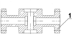
Fig. 1 is the structure sectional view of the utility model;
Fig. 2 is the hermetic unit structure sectional view of the utility model;
Fig. 3 is the round up and down third side's hole structure schematic representation of valve body lumen;
Fig. 4 is the round up and down third side's hole structure schematic representation of valve body lumen.
At Fig. 1; Among Fig. 2: 1. valve body; 2. valve base seal; 3. valve seat insert; 4. valve seat; 5. folded spring; 6. valve plate; 7. guide plate; 8. valve rod; 9. mesopore seal ring; 10. Stem Mut; 11. valve gap; 12. grease pouring valve; 13. stem packing; 14. hex head bolt; 15. studding bolt; 16 Glands; 17. support; 18. Cock screw; 19. lubricating cup; 20. thrust ring; 21. bearing; 22. dust ring; 23. Cock screw; 24. valve bonnet; 25. indication nut; 26. flat key; 27. handwheel; 28. hex head bolt; 29. cover plate; 30. lining; 31. spacer ring; 32. nameplate; 33. rivet.
Specific embodiments
Below in conjunction with Figure of description, the utility model is explained further details:
A kind of no rubber seal valve comprises valve body 1, valve base seal 2, valve seat insert 3, valve seat 4, folded spring 5, valve plate 6, guide plate 7, valve rod 8, mesopore seal ring 9, Stem Mut 10, valve gap 11, grease pouring valve 12, stem packing 13, hex head bolt 14, studding bolt 15, Gland 16, support 17, Cock screw 18, lubricating cup 19, thrust ring 20, bearing 21, dust ring 22, Cock screw 23, valve bonnet 24, indication nut 25, flat key 26, handwheel 27, hex head bolt 28, cover plate 29, lining 30, spacer ring 31, nameplate 32, rivet 33.Wherein said valve seat 4 is embedded among the valve body 1, and folded spring 5 is installed between valve seat 4 and the valve body 1, is connected through bolt between valve gap 11 and the valve body 1; Be connected together through screw thread simultaneously with support 17; Indication nut 25 is installed on the top of support 17, and it plays indicative function to valve rod 8, is connected through screw between handwheel 27 and the valve rod 8; Valve rod 8 is supported in support 17 inwalls through bearing 21, is connected through leading screw between valve plate 6 and the valve rod 8.The guide plate 7 of valve plate 6 cooperates with valve body and moves up and down; Valve base seal 2 and valve seat insert 3 are installed between valve body 1 and the valve seat 4; Mesopore seal ring 9 is installed in valve body 1 and valve gap 11 assembling surface of contact, and stem packing 13 and Gland 16 are installed in the hollow space of valve gap 11 and valve rod 8 formation.
Claims (2)
1. no rubber seal valve; Comprise valve body, valve base seal, valve seat insert, valve seat, folded spring, valve plate, guide plate, valve rod, mesopore seal ring, Stem Mut, valve gap, grease pouring valve, stem packing, hex head bolt, studding bolt, Gland, support, Cock screw, lubricating cup, thrust ring, bearing, dust ring, Cock screw, valve bonnet, indication nut, flat key, handwheel, hex head bolt, cover plate, lining, spacer ring, nameplate, rivet; It is characterized in that described valve seat is embedded among the valve body; Folded spring is installed between valve seat and the valve body; Be connected through bolt between valve gap and the valve body, be connected together through screw thread with support simultaneously, the indication nut is installed on the top of support; Be connected through screw between handwheel and the valve rod; Valve rod, is connected through leading screw between valve plate (6) and the valve rod in rack inner wall through bearings, and valve base seal and valve seat insert are installed between valve body and the valve seat; The mesopore gasket ring is installed in valve body and valve gap assembling surface of contact, and stem packing and Gland are installed in the hollow space of valve gap and valve rod formation.
2. a kind of no rubber seal valve according to claim 1 is characterized in that described valve body lumen is square hole in the middle of justifying up and down, and diameter of a circle equals the diagonal distance of square hole up and down.
Priority Applications (1)
| Application Number | Priority Date | Filing Date | Title |
|---|---|---|---|
| CN2011205446523U CN202520976U (en) | 2011-12-20 | 2011-12-20 | Non-rubber sealing valve |
Applications Claiming Priority (1)
| Application Number | Priority Date | Filing Date | Title |
|---|---|---|---|
| CN2011205446523U CN202520976U (en) | 2011-12-20 | 2011-12-20 | Non-rubber sealing valve |
Publications (1)
| Publication Number | Publication Date |
|---|---|
| CN202520976U true CN202520976U (en) | 2012-11-07 |
Family
ID=47103928
Family Applications (1)
| Application Number | Title | Priority Date | Filing Date |
|---|---|---|---|
| CN2011205446523U Expired - Fee Related CN202520976U (en) | 2011-12-20 | 2011-12-20 | Non-rubber sealing valve |
Country Status (1)
| Country | Link |
|---|---|
| CN (1) | CN202520976U (en) |
Cited By (2)
| Publication number | Priority date | Publication date | Assignee | Title |
|---|---|---|---|---|
| CN106151559A (en) * | 2016-08-17 | 2016-11-23 | 亚新铸造(苏州)有限公司 | There is the flat gate valve of valve plate position indicating function |
| CN108351033A (en) * | 2015-11-10 | 2018-07-31 | 乔治洛德方法研究和开发液化空气有限公司 | It is equipped for the valve of the upper dress formula valve in Cryo Equipment |
-
2011
- 2011-12-20 CN CN2011205446523U patent/CN202520976U/en not_active Expired - Fee Related
Cited By (2)
| Publication number | Priority date | Publication date | Assignee | Title |
|---|---|---|---|---|
| CN108351033A (en) * | 2015-11-10 | 2018-07-31 | 乔治洛德方法研究和开发液化空气有限公司 | It is equipped for the valve of the upper dress formula valve in Cryo Equipment |
| CN106151559A (en) * | 2016-08-17 | 2016-11-23 | 亚新铸造(苏州)有限公司 | There is the flat gate valve of valve plate position indicating function |
Similar Documents
| Publication | Publication Date | Title |
|---|---|---|
| CN202418669U (en) | Flat valve of high sealing property | |
| CN201487284U (en) | Novel fireproof ball valve | |
| CN103591315B (en) | Elasticity C type ring two-seater sealing cage type regulating valve | |
| CN202520976U (en) | Non-rubber sealing valve | |
| CN202418673U (en) | Flat gate valve | |
| CN202790608U (en) | High-temperature high-pressure flat gate valve | |
| CN207122606U (en) | A kind of upper dress formula fixing ball valve for being resistant to worst cold case | |
| CN103470790B (en) | Three eccentric metal seal butterfly valve | |
| CN202992205U (en) | Low load type cutting-off butterfly valve | |
| CN201925504U (en) | Square integrated-cover-type hand-operated rising-stem wedge-shaped gate valve | |
| CN204647338U (en) | Nuclear island Y shape adds pipe arrangement High Temperature High Pressure pressure-relief type Double-clack stop valve | |
| CN202417427U (en) | High/low temperature resistant wellhead valve | |
| CN201627948U (en) | High-temperature high-pressure flat-plate gate valve | |
| CN202302272U (en) | Valve rod sealing structure for copious-cooling butterfly valve under ultralow-temperature operation conditions | |
| CN201705943U (en) | Integrated push rod sealing assembly | |
| CN203384390U (en) | Triple eccentric two-way hard sealed butterfly valve | |
| CN203585359U (en) | Triple-eccentric metal sealing butterfly valve | |
| CN203627832U (en) | Double-base sealed cage type regulating valve with elastic C-shaped ring | |
| CN207178723U (en) | A kind of floating type hard sealing structure in metal valve | |
| CN103711935A (en) | Valve seat structure of track ball valve | |
| CN202955244U (en) | Spherical surface hard seal butterfly valve | |
| CN204437318U (en) | A kind of improved flat gate valve | |
| CN202418672U (en) | Double-sealed flat plate valve | |
| CN203784356U (en) | T-shaped elastic valve seat sealing structure of V-shaped adjusting ball valve | |
| CN207145719U (en) | A kind of improved structure of metal valve body |
Legal Events
| Date | Code | Title | Description |
|---|---|---|---|
| C14 | Grant of patent or utility model | ||
| GR01 | Patent grant | ||
| CF01 | Termination of patent right due to non-payment of annual fee |
Granted publication date: 20121107 Termination date: 20151220 |
|
| EXPY | Termination of patent right or utility model |