CN202513225U - Battery electrode contact component - Google Patents
Battery electrode contact component Download PDFInfo
- Publication number
- CN202513225U CN202513225U CN2012201589433U CN201220158943U CN202513225U CN 202513225 U CN202513225 U CN 202513225U CN 2012201589433 U CN2012201589433 U CN 2012201589433U CN 201220158943 U CN201220158943 U CN 201220158943U CN 202513225 U CN202513225 U CN 202513225U
- Authority
- CN
- China
- Prior art keywords
- plate
- battery electrode
- base plate
- electrode contact
- contact
- Prior art date
- Legal status (The legal status is an assumption and is not a legal conclusion. Google has not performed a legal analysis and makes no representation as to the accuracy of the status listed.)
- Expired - Fee Related
Links
Images

Classifications
-
- Y—GENERAL TAGGING OF NEW TECHNOLOGICAL DEVELOPMENTS; GENERAL TAGGING OF CROSS-SECTIONAL TECHNOLOGIES SPANNING OVER SEVERAL SECTIONS OF THE IPC; TECHNICAL SUBJECTS COVERED BY FORMER USPC CROSS-REFERENCE ART COLLECTIONS [XRACs] AND DIGESTS
- Y02—TECHNOLOGIES OR APPLICATIONS FOR MITIGATION OR ADAPTATION AGAINST CLIMATE CHANGE
- Y02E—REDUCTION OF GREENHOUSE GAS [GHG] EMISSIONS, RELATED TO ENERGY GENERATION, TRANSMISSION OR DISTRIBUTION
- Y02E60/00—Enabling technologies; Technologies with a potential or indirect contribution to GHG emissions mitigation
- Y02E60/10—Energy storage using batteries
Landscapes
- Battery Mounting, Suspending (AREA)
- Connection Of Batteries Or Terminals (AREA)
Abstract
The utility model discloses a battery electrode contact component, which comprises a contact plate (1) and a bottom plate (2), wherein the contact plate (1) and the bottom plate (2) form an integral metal structure, and are arranged to form an L shape; a connecting plate (3) keeping electrical conductive connection with the contact plate (1) is arranged on the bottom plate (2); and a wire mounting hole (31) for mounting a wire is formed in the connecting plate (3). The battery electrode contact component has the advantages of connection reliability, low cost and high machining efficiency and is easy to mount.
Description
Technical field
The utility model relates to power supply auxiliary products field, is specifically related to a kind of battery electrode contact assembly.
Background technology
At present in the electronic product field; Especially the electronic toy product scope often uses battery in a large number; In order to realize to the installing and fixing of battery, all pass through mould at present and make battery case, realize fixing to battery in the form of battery case set inside battery electrode contact assembly then.
But the battery electrode contact assembly of prior art often adopts the form of welding to link to each other with the circuit board of equipment, but welding often needs special equipment; Dependence to equipment is higher; And welding the time needs the certain basis solder technology, therefore to labor claim also than higher, the unstable problem of welding takes place easily; Influence the equipment reliability of electrical connection, but also easily because supplementary materials such as scolding tin cause the injury to workman's health.
Summary of the invention
The technical problem that the utility model will solve provides a kind of battery electrode contact assembly simple, that connection is reliable, cost is low, working (machining) efficiency is high of installing.
For solving the problems of the technologies described above, the technical scheme that the utility model adopts is:
A kind of battery electrode contact assembly; The contact plate and the base plate that comprise the integral type metal structure; L-shaped layout between said contact plate and the base plate, said base plate are provided with the connecting plate that keeps being electrically connected conducting with contact plate, and said connecting plate is provided with the lead installing hole that is used to install lead.
Further improvement as technique scheme:
Said contact plate is provided with and electrically contacts salient point, saidly electrically contacts salient point and is located at the side that said contact plate leans on base plate.
The end of said base plate is provided with mounting panel, and said mounting panel is provided with location hole.
The utlity model has following advantage:
The utility model comprises the contact plate and the base plate of integral type metal structure; L-shaped layout between contact plate and the base plate; Base plate is provided with the connecting plate that keeps being electrically connected conducting with contact plate, and connecting plate is provided with the lead installing hole that is used to install lead, through the lead installing hole can simple realization the utility model the electrical connection conducting; Need not to carry out welding procedure, have and install simply, connect reliable, low, the advantage of high processing efficiency of cost.
Description of drawings
In order to be illustrated more clearly in the utility model embodiment or technical scheme of the prior art; To do to introduce simply to the accompanying drawing of required use in embodiment or the description of the Prior Art below; Obviously, the accompanying drawing in describing below only is some embodiment of the utility model, for those of ordinary skills; Under the prerequisite of not paying creative work, can also obtain other accompanying drawing according to these accompanying drawings.
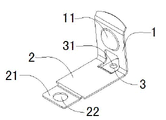
Fig. 1 is the perspective view of the utility model embodiment.
Fig. 2 is the side-looking structural representation of the utility model embodiment.
Marginal data:
1, contact plate; 11, electrically contact salient point;
2, base plate; 21, mounting panel; 22, location hole;
3, connecting plate; 31, lead installing hole.
Embodiment
Below in conjunction with accompanying drawing the preferred embodiments of the present invention are set forth in detail, thereby protection scope of the present invention is made more explicit defining so that advantage of the present invention and characteristic can be easier to it will be appreciated by those skilled in the art that.
As depicted in figs. 1 and 2; The battery electrode contact assembly of present embodiment comprises the contact plate 1 and base plate 2 of integral type metal structure; L-shaped layout between contact plate 1 and the base plate 2; Base plate 2 is provided with contact plate 1 and keeps being electrically connected the connecting plate 3 of conducting, and connecting plate 3 is provided with the lead installing hole 31 that is used to install lead.
The contact plate 1 of present embodiment is provided with and electrically contacts salient point 11, electrically contacts salient point 11 and is located at the side that contact plate 1 leans on base plate 2.
The end of the base plate 2 of present embodiment is provided with mounting panel 21, and mounting panel 21 is provided with location hole 22.
The above is merely the preferred implementation of the utility model, and the protection range of the utility model is not limited in above-mentioned execution mode, and every technical scheme that belongs to the utility model principle all belongs to the protection range of the utility model.For a person skilled in the art, some improvement and the retouching under the prerequisite of the principle that does not break away from the utility model, carried out, these improvement and retouching also should be regarded as the protection range of the utility model.
Claims (3)
1. battery electrode contact assembly; It is characterized in that: the contact plate (1) and the base plate (2) that comprise the integral type metal structure; L-shaped layout between said contact plate (1) and the base plate (2); Said base plate (2) is provided with the connecting plate (3) that keeps being electrically connected conducting with contact plate (1), and said connecting plate (3) is provided with the lead installing hole (31) that is used to install lead.
2. battery electrode contact assembly according to claim 1 is characterized in that: said contact plate (1) is provided with and electrically contacts salient point (11), saidly electrically contacts salient point (11) and is located at the side that said contact plate (1) leans on base plate (2).
3. battery electrode contact assembly according to claim 2 is characterized in that: the end of said base plate (2) is provided with mounting panel (21), and said mounting panel (21) is provided with location hole (22).
Priority Applications (1)
| Application Number | Priority Date | Filing Date | Title |
|---|---|---|---|
| CN2012201589433U CN202513225U (en) | 2012-04-16 | 2012-04-16 | Battery electrode contact component |
Applications Claiming Priority (1)
| Application Number | Priority Date | Filing Date | Title |
|---|---|---|---|
| CN2012201589433U CN202513225U (en) | 2012-04-16 | 2012-04-16 | Battery electrode contact component |
Publications (1)
| Publication Number | Publication Date |
|---|---|
| CN202513225U true CN202513225U (en) | 2012-10-31 |
Family
ID=47065683
Family Applications (1)
| Application Number | Title | Priority Date | Filing Date |
|---|---|---|---|
| CN2012201589433U Expired - Fee Related CN202513225U (en) | 2012-04-16 | 2012-04-16 | Battery electrode contact component |
Country Status (1)
| Country | Link |
|---|---|
| CN (1) | CN202513225U (en) |
Cited By (1)
| Publication number | Priority date | Publication date | Assignee | Title |
|---|---|---|---|---|
| CN107078264A (en) * | 2014-11-20 | 2017-08-18 | 奥迪股份公司 | Accumulator equipment, contact element and the method for manufacturing accumulator equipment |
-
2012
- 2012-04-16 CN CN2012201589433U patent/CN202513225U/en not_active Expired - Fee Related
Cited By (2)
| Publication number | Priority date | Publication date | Assignee | Title |
|---|---|---|---|---|
| CN107078264A (en) * | 2014-11-20 | 2017-08-18 | 奥迪股份公司 | Accumulator equipment, contact element and the method for manufacturing accumulator equipment |
| US10355260B2 (en) | 2014-11-20 | 2019-07-16 | Audi Ag | Energy storage arrangement, contacting element, and method for producing an energy storage arrangement |
Similar Documents
| Publication | Publication Date | Title |
|---|---|---|
| CN101212097B (en) | Electrical connector terminal | |
| CN202513225U (en) | Battery electrode contact component | |
| CN203941199U (en) | Electric energy meter | |
| CN202488880U (en) | PCB (printed circuit board) capable of preventing hole from being plugged in tin soldering | |
| CN206061291U (en) | A kind of loose-leaf printed circuit-board assembly | |
| CN204205187U (en) | Connector combination | |
| CN203950280U (en) | The active pointer with capacitance induction system | |
| CN203466378U (en) | Printed circuit board electrical connector module grounding structure | |
| CN203659302U (en) | Direct-connection combination experimental board | |
| CN203574183U (en) | USB socket and electronic device | |
| CN207426242U (en) | Spring slice fixing structure | |
| CN202649267U (en) | Electric energy meter | |
| CN102969292B (en) | Integrated power supply module | |
| CN202026529U (en) | Printed circuit board | |
| CN205491528U (en) | Electronic equipment and shell structure thereof | |
| CN109587947A (en) | A kind of circuit board | |
| CN206302448U (en) | Mobile terminal | |
| CN203871599U (en) | Ultrathin front-plugboard type long-life connector | |
| CN205282707U (en) | Electrical connection device and electrical connection ware | |
| CN204885532U (en) | Connector takes precautions against earthquakes | |
| CN204652147U (en) | Can the syndeton of standardized flat motor and flat motor and circuit board | |
| CN204335149U (en) | Pad structure and circuit board | |
| CN203801101U (en) | LED power supply with grounding protection | |
| CN202564448U (en) | Contact electrode for battery installation boxes | |
| CN208157614U (en) | The connection structure of antenna and metal edge frame |
Legal Events
| Date | Code | Title | Description |
|---|---|---|---|
| C14 | Grant of patent or utility model | ||
| GR01 | Patent grant | ||
| C17 | Cessation of patent right | ||
| CF01 | Termination of patent right due to non-payment of annual fee |
Granted publication date: 20121031 Termination date: 20140416 |