Novel slit shower nozzle and flush coater head thereof
Technical field
The utility model relates to a kind of battery electrode that can be used for spraying, and especially sprays the novel slit shower nozzle and the flush coater head thereof of GND.
Background technology
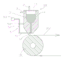
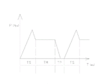
The electrode of battery generally applies one deck slurry and realizes on base material, if apply be anode slurry then be the anode sheet material, if apply the cathode size that is then be negative electrode plate.On base material, apply the way of slurry now, adopt the clearance-type coating machine mostly, the head of this coating machine mainly comprises the edge of a knife; Drive roll, back flow roll, hopper; Back flow roll carries out the gap contact with respect to drive roll, thereby the slurry on the drive roll is transferred on the base material, because slurry at first will be transferred on the drive roll from hopper; Regulate the thickness of slurry again through the last edge of a knife; And transfer to again on the base material on the back flow roll, this coating machine slurry makes the thickness of last slurry on base material be difficult to control through repeatedly shifting.In recent years, People more and more hopes to have a kind of new technology to replace the technology of gap coating, makes that the coating of slurry on base material is more even.Therefore; The slit spraying technology begins to be applied in the electrode coating of battery, and at present, the head of the jet printing type coating machine of the electrode of battery industry coating is the coating machine head improvement from the enamel powder; The anode less for pulp particle applies; Effect is all right, and still, just there are some problems in the negative pole bigger to particle (about 20 μ m); The head of this jet printing type coating machine comprises slit shower nozzle 100, slurry supply pump 110, slurry discharging pump 120, narrow slit type nozzle 130, drive roll 140 and the base material 150 that rotates with drive roll; Said slit shower nozzle 100 is horizontally disposed with, the narrow slit type nozzle 130 of slit shower nozzle 100 and said base material 150 adjacency (referring to Fig. 9 and Figure 10), slurry supply pump 110 and the slurry discharging pump 120 general screw pumps that adopt.During use, open slurry supply pump 110 and slurry discharging pump 120, adjustment slurry supply pump 110 and slurry discharging pump 120 pressure reduction; When the input pressure of slurry supply pump 110 during greater than the output pressure of slurry discharging pump 120, just have slurry from narrow slit type nozzle 130 ejections, on base material, form one deck electrode 160; After electrode 160 reaches preset distance, adjust slurry supply pump 110 and slurry discharging pump 120 pressure reduction again, make slurry supply pump 110 and slurry discharging pump 120 pressure reduction be equal to or less than zero; At this moment; Narrow slit type nozzle 130 stops the spray material, and base material continues to move ahead, and forms gap 170.This flush coater is the design according to product; Change slurry supply pump 110 through PLC by preset program and realize the coating of slurry on base material 150 with slurry discharging pump 120 pressure reduction; As everyone knows; The stiction of the liquid slurry that viscosity is higher is greater than flowage friction power; If be set to equal to overcome the size of flowage friction power at coating initial stage slurry supply pump 110 and slurry discharging pump 120 pressure reduction, certainly will, electrode will lift one's head thin phenomenon (thickness of electrode does not reach design thickness) like this when beginning to be coated with, and this is unallowed.In order to overcome this problem, just slurry supply pump 110 and slurry discharging pump 120 pressure reduction are set to equal to overcome the size (seeing Figure 11) of stiction, coating initial time TS in programming; Recall to again and equal to overcome flowage friction power size; The even cloth time T M of coating is made as zero with slurry supply pump 110 and slurry discharging pump 120 pressure reduction at last again, and operation stops spray material time T P; Form gap 170, accomplish the coating of an electrode; Then, the coating that goes round and begins again so again forms several electrodes.
There are two main problems in the flush coater of this structure, and the one, it is thick to start, and the 2nd, gap 170 instabilities.Starting thick is because at spraying initial time TS; In order to overcome slurry at narrow slit type nozzle 130 stiction; And the pressure reduction of slurry supply pump 110 that adopts and slurry discharging pump 120 is greater than the pressure reduction that overcomes flowage friction power; Thereby cause thickness of electrode in initial time TS greater than designing requirement, be called thick head in the industry; The 2nd, the gap is unstable; The gap shakiness is because when the pressure reduction of adjustment slurry supply pump 110 and slurry discharging pump 120; Slurry supply pump 110 all has a response speed problem with slurry discharging pump 120 and slurry flowing in narrow slit type nozzle 130; At present, existing flush coater is unstable in the response speed that slurry supply pump 110, slurry discharging pump 120 and slurry flow in narrow slit type nozzle 130, thus during the gap width that causes wide advance narrow; The gap is very unstable, causes a lot of troubles to later process.In addition; Also there is a peripheral issue in this flush coater, is exactly on electrode, to form striped easily, and the narrow slit type nozzle 130 of this flush coater can only horizontal arrangement; Service time is long slightly; Particle in the viscosity slurry adheres to the local obstruction of the formation of uniting in the exit 131 of narrow slit type nozzle 130, thereby is forming uncoated striped with the corresponding electrode of blocking portion under the gravity effect.Therefore, this situation appears and after, then need shut down and clean narrow slit type nozzle 130, thereby cause work discontinuous, whole production line is shut down, and loses very greatly, has improved the manufacturing cost of electrode greatly.
The utility model content
The purpose of the utility model is to the problems referred to above, provides a kind of coating even to society, and stable slit shower nozzle and the flush coater head thereof in gap.
Another purpose of the utility model provides a kind of slit shower nozzle and flush coater head thereof that in coating process, is difficult for producing striped.
The technical scheme of the utility model is: a kind of novel slit shower nozzle is provided, comprises:
-nozzle body is provided with containing cavity and narrow slit type nozzle in said nozzle body, said containing cavity and narrow slit type nozzle communicate;
-constant pressure air feeding system is given in the said containing cavity pressure-sustaining gas is provided;
-slurry supply control system comprises slurry feedway and tank level control system, and tank level control system keeps the liquid level in the containing cavity constant according to the duty of the control of the slurry liquid level in containing cavity slurry feedway;
-narrow slit type nozzle switch controlling device, the signal according to main control unit opens or closes narrow slit type nozzle.
As improvement to the utility model; Said nozzle body comprises symmetrically arranged left template and right template; Front side board, back side panel and upper plate; Said front side board, back side panel and upper plate are connected with right formwork seal with said left template, and said left template bottom is left die lip down, and left side die lip inboard down curves upper left template in making progress; Said right template bottom is the bottom right die lip, curves upper right template in die lip inboard in bottom right makes progress; Under the said left side between die lip and the bottom right die lip gap certain distance be formed for flowing out the narrow slit type nozzle of slurry; Form containing cavity between said upper left template and the upper right template with the splendid attire slurry.
As the improvement to the utility model, under the said left side in die lip and the bottom right die lip is longer than die lip under the another one.
As improvement, on long following die lip, be provided with the strip groove of the blade that is used to insert the narrow slit type nozzle switch controlling device to the utility model.
As the improvement to the utility model, die lip and/or the bottom right die lip outside is provided with the microspur adjusting device that is used to finely tune slit width under a said left side.
As the improvement to the utility model, said narrow slit type nozzle switch controlling device comprises blade, and the blade outside connects the drive rod lower end, and the drive rod upper end connects driver, is provided with fulcrum between the two ends of drive rod.
As the improvement to the utility model, said constant pressure air feeding system comprises:
-pressure transmitter converts the gas pressure in the containing cavity into data-signal, and is transferred to controller,
-gas pressure regulator, gas pressure regulator convert received data-signal into the air pressure control signal, and flow to executive component,
-executive component is carried out corresponding actions according to the air pressure control signal of gas pressure regulator.
As the improvement to the utility model, said slurry feedway is the screw pump of frequency conversion drive.
As the improvement to the utility model, said tank level control system comprises:
-fluid level transmitter converts the liquid level data in the containing cavity into data-signal, and is transferred to fluid level controller,
-fluid level controller, fluid level controller converts received liquid level data signal into the liquid level control signal, and flows to the screw pump of frequency conversion drive, and the screw pump of frequency conversion drive is carried out corresponding actions according to the control signal of fluid level controller.
The utility model also provides a kind of flush coater head, includes the flush coater head of above-mentioned novel slit shower nozzle.
The utility model is owing to adopted constant slurry pressure spraying technology; Replace traditional material to press the coating technique that changes; Can overcome a thick problem that rises and form owing to pressure; The utility model adopted air pressure constant with constant two technological means of liquid level, press purpose constant, that response is fast to reach material, regulating that slit and material just press can well control electrode thickness; In order to guarantee that gaps between electrodes is stable, adopted mechanical narrow slit type nozzle switch controlling device, its blade response speed is fast, can guarantee that the slit shower nozzle realizes that moment opens or closes, and guarantees that the gap is consistent.In addition, the novel slit shower nozzle in the utility model owing to exist constant material to press, makes sticky particle be difficult for being attached to the die lip surface when vertically placing, and just can not produce deposition; When horizontal positioned; Even a small amount of deposition is arranged; Also can owing to blade at the die lip place of narrow slit type nozzle switch back and forth; And removed these small deposited particles by the action back and forth of blade, thereby can not form slurry piles up and the problem of obstruction narrow slit type nozzle at the die lip place of narrow slit type nozzle, can reach to delay the chance that striped occurs; Again, nozzle body adopts module making, the mode of splicing again, and it has makes easily advantage with low cost.
Description of drawings
Fig. 1 is the perspective view of a kind of embodiment of the utility model shower nozzle.
Fig. 2 is the decomposition texture sketch map of nozzle body among Fig. 1.
Fig. 3 is the constant pressure air feeding system frame structure sketch map of the utility model.
Fig. 4 is the slurry supply control system frame structure sketch map of the utility model.
Fig. 5 is the A-A section structure for amplifying sketch map among Fig. 2.
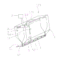
Fig. 6 is the perspective view of a kind of embodiment of flush coater head of the utility model.
Fig. 7 is the cross-sectional view of Fig. 6.
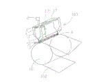
Fig. 8 is the perspective view of another kind of embodiment of the flush coater head of the utility model.
Fig. 9 is the perspective view of existing flush coater head.
Figure 10 is the cross-sectional view of Fig. 9.
Figure 11 is pressure reduction and a change of time graph of a relation embodiment illustrated in fig. 9.
The specific embodiment
See also Fig. 1, what Fig. 1 disclosed is a kind of novel slit shower nozzle 103, comprises nozzle body 1, in said nozzle body 1, is provided with containing cavity 11 and narrow slit type nozzle 12, and said containing cavity 11 communicates with narrow slit type nozzle 12; Constant pressure air feeding system 2 is given in the said containing cavity 11 pressure-sustaining gas is provided; Slurry supply control system 3; Comprise slurry feedway (not drawing among the figure) and tank level control system 4; Tank level control system 4 keeps the liquid level in the containing cavity 11 constant according to the duty of the control of the slurry liquid level in the containing cavity 11 slurry feedway; Narrow slit type nozzle switch controlling device 5 according to the signal of main control unit, opens or closes narrow slit type nozzle 12.Like this, air pressure and liquid level in the containing cavity 11 are constant, just can reach material and press purpose constant, that response is fast, thereby just a thick problem can not occur.
In the utility model, said narrow slit type nozzle switch controlling device 5 comprises blade 51, and blade 51 outsides connect drive rod 52 lower ends, and drive rod 52 upper ends connect driver 53, are provided with fulcrum 54 between the two ends of drive rod 52.Said driver 53 can cylinder or oil cylinder, also can CD-ROM drive motor etc., and when needs are closed narrow slit type nozzle 12, driver 53 shrinks pull bars, and side blade 51 moves round about, narrow slit type nozzle 12 is closed, otherwise then narrow slit type nozzle 12 is opened.The utility model has adopted mechanical narrow slit type nozzle switch controlling device 5, and its blade 51 response speeds are fast, can guarantee that the slit shower nozzle realizes that moment opens or closes, and guarantees that the gap is consistent.
See also Fig. 2; Said nozzle body 1 comprises symmetrically arranged left template 13 and right template 14; Front side board 15, back side panel 16 and upper plate 17; Said front side board 15, back side panel 16 and upper plate 17 are tightly connected through the mode that screw adds packing ring with said left template 13 and right template 14 respectively, and said left template 13 bottoms are left side die lip 131 down, and die lip 131 is inboard down on a left side curves upper left template 132 in upwards; Said right template 14 bottoms are bottom right die lip 141, curve upper right template 142 in bottom right die lip 141 inboard the making progress; Under the said left side between die lip 131 and the bottom right die lip 141 the gap certain distance be formed for flowing out the narrow slit type nozzle 12 of slurry; Form containing cavity 11 between said upper left template 132 and the upper right template 142, on upper plate 17, be provided with viewing window 171 with the splendid attire slurry.In the present embodiment, in order be the slurry water conservancy diversion better, die lip 131 is longer than said bottom right die lip 142 under the said left side, and obviously, the utility model also can be designed to said bottom right die lip 141 than die lip under the said left side 132 is grown or both equate structure.Under a left side, be provided with the strip groove 133 of the blade 51 that is used to insert narrow slit type nozzle switch controlling device 5 on the die lip 131.During use, blade 51 can move back and forth in groove.
In the utility model; Die lip 141 outsides are provided with the microspur adjusting device 6 that is used to finely tune slit width in said bottom right; Said microspur adjusting device 6 is regulated through screw rod 61; This microspur adjusting device 6 can guarantee narrow slit type nozzle 12, and down die lip 131 is parallel with a left side at length direction, and is obvious, also can be provided with the microspur adjusting device 6 with spline structure in 131 outsides of die lip under the left side.
See also Fig. 3, in the utility model, said constant pressure air feeding system 2 comprises pressure transmitter 21; Be arranged on containing cavity 11 internal upper parts, convert the gas pressure in the containing cavity 11 into data-signal, and be transferred to gas pressure regulator 22; Said gas pressure regulator 22 converts received data-signal into the air pressure control signal, and flows to executive component 23; Said executive component 23 is carried out corresponding actions according to the air pressure control signal of gas pressure regulator 22, as opens gas or close gas.It is the pressure transmitter of DG1300-BZ-A that pressure transmitter 21 in the utility model can adopt homemade model, and its precision can reach 0.01Mpa; It is the PID intelligent controller of AL808 that said gas pressure regulator 22 can adopt homemade model; Said executive component 23 can be a magnetic valve, or the air compressor machine of frequency conversion drive, and air compressor machine preferably adopts variable-frequency helical-lobe compressor.
See also Fig. 4, in the utility model, said slurry feedway can adopt the screw pump of frequency conversion drive.Said tank level control system 4 comprises fluid level transmitter 41; Convert the liquid level data in the containing cavity 11 into data-signal, and be transferred to fluid level controller 42, said fluid level controller 42 is with received liquid level data signal; Convert the liquid level control signal into; And flowing to the screw pump 43 of frequency conversion drive, the screw pump 43 of frequency conversion drive is carried out corresponding actions according to the control signal of fluid level controller 42, i.e. feed or stop feed.
See also Fig. 5, Fig. 5 is the planar structure sketch map of the utility model curtain coating formula charging.Slurry is input to left template 13 tops by the screw pump of frequency conversion drive, and the screw pump input/output port 71 entering runners 72 from frequency conversion drive flow in the containing cavities 11 from runner 73 again; Like this; Advance from a big mouth, the mode that a plurality of osculums go out can avoid big mouthful directly slurry to be imported in the containing cavity 11; Original slurry produces fluctuation in the containing cavity 11 and cause, and influence material pressure is stable.Obviously, this feeding structure also can be located on the right template 14.
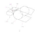
See also Fig. 6 and Fig. 7; What Fig. 6 and Fig. 7 disclosed is a kind of flush coater head 200; Said flush coater head 200 includes vertically disposed aforementioned novel slit shower nozzle 103; Below said novel slit shower nozzle 103, be provided with drive roll 101 and base material 102, said novel slit shower nozzle 103 and said base material adjacency.In the utility model, said base material can Copper Foil band or aluminium foil strip.
See also Fig. 8, Fig. 8 is the perspective view of another kind of embodiment of the flush coater head of the utility model.Embodiment illustrated in fig. 8, to compare with embodiment shown in Figure 7 with Fig. 6, basic general structure is identical, and different is that novel slit shower nozzle 103 is horizontally disposed.Obviously, novel slit shower nozzle 103 is except can horizontal or vertically being provided with, and it can be in the 0-180 degree, with arbitrarily angled setting.
Air pressure described in this paper is constant or liquid level is constant, is not to say so to refer to that air pressure or some variation of liquid level all do not have, and is meant the minor fluctuations in minimum pressure or liquid level scope, is regarded as constant.