CN202497934U - Magnetic system device of high-gradient magnetic separator - Google Patents
Magnetic system device of high-gradient magnetic separator Download PDFInfo
- Publication number
- CN202497934U CN202497934U CN201220041599XU CN201220041599U CN202497934U CN 202497934 U CN202497934 U CN 202497934U CN 201220041599X U CN201220041599X U CN 201220041599XU CN 201220041599 U CN201220041599 U CN 201220041599U CN 202497934 U CN202497934 U CN 202497934U
- Authority
- CN
- China
- Prior art keywords
- magnetic
- separator
- sorting
- magnetic pole
- gradient magnetic
- Prior art date
- Legal status (The legal status is an assumption and is not a legal conclusion. Google has not performed a legal analysis and makes no representation as to the accuracy of the status listed.)
- Expired - Lifetime
Links
- 239000006148 magnetic separator Substances 0.000 title claims abstract description 32
- 238000011084 recovery Methods 0.000 abstract description 2
- 230000007547 defect Effects 0.000 abstract 1
- 229910052500 inorganic mineral Inorganic materials 0.000 description 3
- 239000011707 mineral Substances 0.000 description 3
- 239000011159 matrix material Substances 0.000 description 2
- 238000005516 engineering process Methods 0.000 description 1
- 239000000463 material Substances 0.000 description 1
- 238000005065 mining Methods 0.000 description 1
- 238000000926 separation method Methods 0.000 description 1
Images


Landscapes
- Magnetic Resonance Imaging Apparatus (AREA)
Abstract
A magnetic system device of a high-gradient magnetic separator comprises an upper magnetic pole, a lower magnetic pole, an exciting coil and an end magnet yoke. The upper magnetic pole and the lower magnetic pole are provided with plane type acting surfaces capable of enabling magnetic lines of force in sorting regions to be distributed in the same direction, and magnetic fields in sorting cavities are distributed evenly. The magnetic system device overcomes the defect that cambered acting surfaces of an upper magnetic pole and a lower magnetic pole of a vertical ring pulse high-gradient magnetic separator enable magnetic fields inside sorting cavities to be distributed unevenly. In addition, compared with the vertical ring pulse high-gradient magnetic separator, handling capacity and magnetic field utilizing rate of the high-gradient magnetic separator are improved obviously. Due to the fact that the magnetic fields in the sorting cavities are distributed evenly, grading indexes of the magnetic system device are reduced obviously compared with tailings grade of the vertical ring pulse high-gradient magnetic separator, and the recovery rate is improved obviously.
Description
Technical field
The utility model belongs to the preparation equipment field, particularly relates to a kind of high gradient magnetic separator.
Background technology
The magnetic pastern branch of high gradient magnetic separator is the center that produces and provide magnetic source; Important component part for complete machine; The last lower magnetic pole acting surface of the pulsating high gradient magnetic separator with vertical ring of extensive use at present is arc surface, and is as shown in Figure 1, so the sorting cavity is the space of an arc.Its sorting inside cavity is as shown in Figure 2 along the Distribution of Magnetic Field of center line, can find out, the Distribution of Magnetic Field in arc sorting cavity on the center line is parabola shaped, and promptly sorting cavity central magnetic field intensity is high, and the both sides magnetic field intensity is low.This distribution mode of magnetic field intensity is disadvantageous to sorting of mineral; Centre at the sorting cavity; The mineral of fine grained and weak magnetic are attracted to the surface of magnetic matrix, but in medium goes to separation ring during the mining area because the magnetic field intensity reduction, the particulate weak magnetic mineral that is adsorbed on the magnetic matrix can turn back in the mine tailing again; Cause the grade of mine tailing to raise, reduced the sorting index of equipment.
Summary of the invention
The purpose of the utility model is the existence to the problems referred to above, and the magnetic that provides a kind of and can effectively solve high gradient magnetic separator arc sorting cavity internal magnetic field problem pockety, has the pulsating high gradient magnetic separator of uniform magnetic field distribution is device.
The purpose of the utility model realizes through following technical scheme:
A kind of magnetic of high gradient magnetic separator is device; Comprise magnetic pole, lower magnetic pole, magnetizing coil, end yoke; Be characterized in that said magnetic pole and the lower magnetic pole gone up is provided with and can makes that magnetic line of force trend is unidirectional plane acting surface in the branchs favored area of place, and the interior magnetic field of said sorting cavity distributes evenly.
Wherein, above-mentioned sorting chamber body structure is cuboid or square, and the trend of the magnetic line of force is vertical direction or horizontal direction in this sorting cavity.
Above-mentioned magnetizing coil is at least one, and this magnetizing coil is arranged in any position of magnetic system.
Above-mentioned sorting chamber body is positioned at the centre of magnetic system or the periphery of magnetic system.
The utility model is owing to adopted the magnetic architecture that can produce the uniform magnetic field distribution; Overcome original vertical ring high-gradient magnetic separator sorting cavity internal magnetic field shortcoming pockety; Make whole sorting cavity internal magnetic field be evenly distributed; The magnetisable material that is adsorbed on the dielectric rod can not come off in sorting cavity scope, has reduced tailings grade effectively, has improved the rate of recovery.Simultaneously owing to be positioned at the medium volume in sorting cavity high field intensity zone and compare and have vertical ring high-gradient magnetic separator now increase is by a relatively large margin arranged, the treating capacity of equipment also can be significantly improved.
Describe the realization of the utility model in detail below in conjunction with accompanying drawing.
Description of drawings
Fig. 1 is the magnetic architecture sketch map of existing high gradient magnetic separator.
Fig. 2 is the Distribution of Magnetic Field sketch map on the existing high gradient magnetic separator arc sorting inside cavity center line.
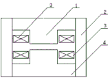
Fig. 3 is that the magnetic of the described high gradient magnetic separator of the utility model is the sketch map of device embodiment I.
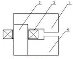
Fig. 4 is that the magnetic of the described high gradient magnetic separator of the utility model is the sketch map of device embodiment II.
Fig. 5 is that the magnetic of the described high gradient magnetic separator of the utility model is the sketch map of device embodiment III.
Fig. 6 is that the magnetic of the described high gradient magnetic separator of the utility model is the sketch map of device embodiment IV.
Fig. 7 is that the magnetic of the described high gradient magnetic separator of the utility model is the sketch map of device embodiment V.
Fig. 8 is that the magnetic of the described high gradient magnetic separator of the utility model is the sketch map of device embodiment VI.
Fig. 9 is that the magnetic of the described high gradient magnetic separator of the utility model is the sketch map of device embodiment VII.
Figure 10 is that the magnetic of the described high gradient magnetic separator of the utility model is the sketch map of device embodiment VIII.
Figure 11 is that the magnetic of the described high gradient magnetic separator of the utility model is the sketch map of device embodiment IX.
Figure 12 is that the magnetic of the described high gradient magnetic separator of the utility model is the sketch map of device embodiment X.
The specific embodiment
Like Fig. 3~shown in Figure 10; The described high gradient magnetic separator of the utility model is a device with magnetic; Comprise magnetic pole 1, lower magnetic pole 4, magnetizing coil 3, end yoke 2; Said magnetic pole 1 and the lower magnetic pole 4 gone up is provided with and can makes that magnetic line of force trend is unidirectional plane acting surface in the branchs favored area of place, and the interior magnetic field of said sorting cavity evenly distributes.Wherein, above-mentioned sorting chamber body structure is cuboid or square, and the trend of the magnetic line of force is vertical direction or horizontal direction in this sorting cavity.Above-mentioned magnetizing coil 3 is at least one, and this magnetizing coil 3 is arranged in any position of magnetic system.Above-mentioned sorting chamber body is positioned at the centre of magnetic system or the periphery of magnetic system, as long as guarantee that the trend of the magnetic line of force in the sorting cavity is vertical direction or horizontal direction.
Claims (4)
1. the magnetic of a high gradient magnetic separator is device; Comprise magnetic pole (1), lower magnetic pole (4), magnetizing coil (3), end yoke (2); It is characterized in that said magnetic pole (1) and the lower magnetic pole (4) gone up is provided with and can makes that magnetic line of force trend is unidirectional plane acting surface in the branchs favored area of place, and the interior magnetic field of said sorting cavity distributes evenly.
2. the magnetic of high gradient magnetic separator according to claim 1 is device, it is characterized in that above-mentioned sorting chamber body structure is cuboid or square, and the trend of the magnetic line of force is vertical direction or horizontal direction in this sorting cavity.
3. the magnetic of high gradient magnetic separator according to claim 1 is device, it is characterized in that above-mentioned magnetizing coil (3) is at least one, and this magnetizing coil (3) is arranged in any position of magnetic system.
4. the magnetic of high gradient magnetic separator according to claim 1 is device, it is characterized in that above-mentioned sorting chamber body is positioned at the centre of magnetic system or the periphery of magnetic system.
Priority Applications (1)
| Application Number | Priority Date | Filing Date | Title |
|---|---|---|---|
| CN201220041599XU CN202497934U (en) | 2012-02-09 | 2012-02-09 | Magnetic system device of high-gradient magnetic separator |
Applications Claiming Priority (1)
| Application Number | Priority Date | Filing Date | Title |
|---|---|---|---|
| CN201220041599XU CN202497934U (en) | 2012-02-09 | 2012-02-09 | Magnetic system device of high-gradient magnetic separator |
Publications (1)
| Publication Number | Publication Date |
|---|---|
| CN202497934U true CN202497934U (en) | 2012-10-24 |
Family
ID=47034562
Family Applications (1)
| Application Number | Title | Priority Date | Filing Date |
|---|---|---|---|
| CN201220041599XU Expired - Lifetime CN202497934U (en) | 2012-02-09 | 2012-02-09 | Magnetic system device of high-gradient magnetic separator |
Country Status (1)
| Country | Link |
|---|---|
| CN (1) | CN202497934U (en) |
Cited By (1)
| Publication number | Priority date | Publication date | Assignee | Title |
|---|---|---|---|---|
| CN102553713A (en) * | 2012-02-09 | 2012-07-11 | 广州粤有研矿物资源科技有限公司 | Magnetic system device for high-gradient magnetic separator |
-
2012
- 2012-02-09 CN CN201220041599XU patent/CN202497934U/en not_active Expired - Lifetime
Cited By (1)
| Publication number | Priority date | Publication date | Assignee | Title |
|---|---|---|---|---|
| CN102553713A (en) * | 2012-02-09 | 2012-07-11 | 广州粤有研矿物资源科技有限公司 | Magnetic system device for high-gradient magnetic separator |
Similar Documents
| Publication | Publication Date | Title |
|---|---|---|
| CN102553713A (en) | Magnetic system device for high-gradient magnetic separator | |
| CN106746146B (en) | A high-throughput magnetic solid-liquid separation device and its method for purifying magnetic particles in wastewater | |
| CN103240176B (en) | The configuration structure of the reciprocal tank of a kind of high gradient superconducting magnetic seperator | |
| CN102335638A (en) | High-gradient magnetic flux converging medium for high intensity magnetic separator | |
| CN202497934U (en) | Magnetic system device of high-gradient magnetic separator | |
| CN103071586A (en) | High-gradient electric permanent magnetic separator | |
| CN203061279U (en) | High-gradient magnetic separator of periodic horizontal magnet system | |
| CN102327811B (en) | Permanent magnet vertical ring high gradient strong magnetic separator | |
| CN105289842A (en) | Large column type magnetic separator of internal magnetic system | |
| CN101630565B (en) | Device for constituting permanent magnet full-acting surface | |
| CN202290290U (en) | Permanent magnet vertical ring high-gradient strong magnetic separator | |
| CN202860686U (en) | Network medium box for vertical ring type high-intensity magnetic separator | |
| CN202538920U (en) | Continuous ultrasonic-assisted superconducting magnetic separation device with high gradient | |
| CN204769104U (en) | Immediately, coil high gradient magnetic disc device of magnet separator | |
| CN203862379U (en) | Permanent-magnet high-field-intensity magnetic system | |
| CN201720123U (en) | Magnetic separation device of fed ore pulp stream | |
| CN203862378U (en) | Reciprocating permanent-magnet high-field-intensity magnetic filter | |
| CN101823020A (en) | Permanent magnet vibration module type magnetic separator | |
| CN201430045Y (en) | Device forming permanent-magnet full acting surface | |
| CN102773159A (en) | Magneto-Archimedes buoyancy-based impurity separating method | |
| CN201959861U (en) | Permanent-magnet cylindrical cage type high-gradient magnetic separator with uniform background magnetic field work area | |
| CN205164934U (en) | Energy -conserving magnet separator with gradient magnetic force | |
| CN207786812U (en) | Permanent magnetism magnetic floating dry type strong magnetic separator | |
| CN203635317U (en) | Dropping and sputtering prevention rotating ring of vertical ring high-intensity magnetic separation machine | |
| CN207266891U (en) | A kind of netted induction medium device of high gradient magnetic separator |
Legal Events
| Date | Code | Title | Description |
|---|---|---|---|
| C14 | Grant of patent or utility model | ||
| GR01 | Patent grant | ||
| CX01 | Expiry of patent term | ||
| CX01 | Expiry of patent term |
Granted publication date: 20121024 |