Permanent magnet vertical ring high gradient intensity magnetic separator
Technical field
The utility model relates to the preparation equipment technical field, relates in particular to a kind of permanent magnet vertical ring high gradient intensity magnetic separator.
Background technology
For more weak mineral of magnetic such as picture manganese ore, chromite, ilmenite, wolframite, beach sand, garnet, martites; Adopt the permanent-magnet drum type magnetic separator of opening magnetic system also sufficiently high magnetic field intensity and magnetic field gradient can't be provided at present, can only rely on the electromagnetism intensity magnetic separator.The high gradient intensity magnetic separator of using in the existing industry mainly contains electromagnetism horizontal disk high gradient intensity magnetic separator and electromagnetism vertical ring high-gradient intensity magnetic separator.Electromagnetism horizontal disk high gradient intensity magnetic separator is replaced by electromagnetism vertical ring high-gradient intensity magnetic separator owing to there is mechanical blockage problem gradually.Electromagnetism vertical ring high-gradient intensity magnetic separator is in the magnetic field that solenoid produces; Adopt the induced field of magnetic conductive media generation high gradient and weak magnetic mineral is carried out sorting; In order to improve separating effect; What have is added with palsating equipment on the sorting space, make ore pulp in the sorting space, pump, and has improved separation index.
But the upright ring of the electromagnetism of using in existing industry intensity magnetic separator all produces magnetic field with the excitatory mode of solenoid, is example with the upright ring of 2 meters of diameters, and only excitatory power just up to more than 40 kilowatts, need consume a large amount of electric energy in process of production; In addition, the electromagnetic separator complex structure not only needs special-purpose high-power excitation power supply, but also will carry out cooling processing to solenoid, and operation expense is very high.
The utility model content
The technical problem that (one) will solve
The technical problem that the utility model will solve is: a kind of permanent magnet vertical ring high gradient intensity magnetic separator is provided, when realization is reclaimed some weak magnetic minerals, solves the problem of the highly energy-consuming of the upright ring of above-mentioned electromagnetism intensity magnetic separator.
(2) technical scheme
For addressing the above problem; The utility model provides a kind of permanent magnet vertical ring high gradient intensity magnetic separator; Comprise drive unit, the separation ring of vertically installing and being driven by said drive unit and be located in ring section portion permanent magnetic system on every side said separation ring under, said permanent magnetic system comprises the permanent magnetism magnetic pole group and is located at the upper magnet yoke and the lower yoke of said permanent magnetism magnetic pole group upper and lower respectively.
Preferably, said permanent magnetic system comprises two groups of permanent magnetism magnetic pole groups, and the magnetizing direction of said two groups of permanent magnetism magnetic pole groups is vertical direction and polarity is identical.
Preferably, said intensity magnetic separator also comprise rack-mounted axle bed, be installed on the said axle bed and by the main shaft of said drive unit driven in rotation, be fixed on the connector on the said main shaft and be fixed on said connector and said separation ring between disc.
Preferably; Said separation ring comprises two semicircular ring; Said disc comprise two respectively with the semicircle disc of said two corresponding connections of semicircular ring, be respectively equipped with said connector on said two semicircle disc, saidly lay respectively at two connectors on the semicircle disc and interconnect and fix with said main shaft; Said separation ring perisporium is distributed with a plurality of magnetizing mediums rods along being circumferentially with a plurality of magnetizing mediums boxes on said each magnetizing mediums box.
Preferably, be provided with the gap that supplies said separation ring to pass between the upper magnet yoke of said permanent magnetic system and the lower yoke, and lay respectively at and be provided with the gap that supplies said disc to pass between two upper magnet yokes on said two permanent magnetism magnetic pole groups.
Preferably, said disc is connected in the axial middle part of said separation ring, and the part that said upper magnet yoke is positioned at ring section portion top under the said separation ring is provided with the charging slit.
Preferably, the said upper magnet yoke bottom that is positioned under the said separation ring ring section portion upper section has the radian corresponding with said separation ring.
Preferably, the side near said separation ring between said upper magnet yoke and the lower yoke connects through gripper shoe, passes through screw rod away from a side of said separation ring and connects.
Preferably, said permanent magnetism magnetic pole group adopts Nd-Fe-Bo permanent magnet material.
Preferably, sealing is provided with corrosion resistant plate around the said permanent magnetism magnetic pole group.
(3) beneficial effect
The utility model is through the sorting space of permanent magnetic system around separation ring formation high magnetic field intensity and gradient, few, the good separation effect of its power consumption.And the intensity magnetic separator of the utility model is simple in structure, cost is low.
Description of drawings
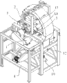
Fig. 1 is the perspective view according to the intensity magnetic separator of the utility model embodiment;
Fig. 2 is the Facad structure sketch map according to the intensity magnetic separator of the utility model embodiment;
Fig. 3 is the side structure sketch map according to the intensity magnetic separator of the utility model embodiment;
Fig. 4 is the perspective view according to the utility model embodiment permanent magnetic system;
Fig. 5 is the perspective view according to separation ring and the connector thereof of the utility model embodiment;
Wherein: 1: drive unit; 2: separation ring; 3: permanent magnetic system; 4: frame; 5: axle bed; 6: main shaft; 7: connector; 8: disc; 9: the mine tailing case; 10: debris tube; 11: the chats case; 12: middle pipe; 13: the concentrate case; 14: the concentrate pipe; 21: semicircular ring; 22: the magnetizing mediums box; 23: the magnetizing mediums rod; 31: the permanent magnetism magnetic pole group; 32: upper magnet yoke; 33: lower yoke; 34: gripper shoe; 35: screw rod; 81: the semicircle disc; 321: the charging slit.
The specific embodiment
Below in conjunction with accompanying drawing and embodiment the utility model is elaborated as follows.
Like Fig. 1-shown in Figure 3 is the structural representation of the intensity magnetic separator of the utility model embodiment.The permanent magnet vertical ring high gradient intensity magnetic separator of the utility model; Comprise drive unit 1, vertically (promptly axially being horizontally disposed with) and separation ring 2 that is driven by said drive unit 1 and the permanent magnetic system 3 that acts on 2 times rings of said separation ring section portion be installed, said permanent magnetic system 3 encircles for 2 times around the section portion for being located in said separation ring.
Fig. 4 is the structural representation of the permanent magnetic system of the utility model embodiment.As shown in Figure 4, said permanent magnetic system 3 comprises two groups of permanent magnetism magnetic pole groups, and the magnetizing direction of said two groups of permanent magnetism magnetic pole groups is vertical direction and polarity is identical.
Fig. 5 is the separation ring of the utility model embodiment and the structural representation of connector thereof.As shown in Figure 5, said intensity magnetic separator also comprises the axle bed 5 that is installed on the frame 4, be installed on the said axle bed 5 and by the main shaft 6 of said drive unit 1 driven in rotation, be fixed on the connector 7 on the said main shaft 6 and be fixed on the disc 8 between said connector 7 and the said separation ring 2.The power that the motor of drive unit 1 produces is passed on the main shaft 6 after slowing down through reductor, makes main shaft 6 on axle bed 5, rotate, and then drive connector 7, disc 8 and separation ring 2 rotate synchronously.
Said separation ring 2 comprises two semicircular ring 21; Said disc 8 comprise two respectively with the semicircle disc 81 of said two semicircular ring, 21 corresponding connections; Be respectively equipped with said connector 7 on said two semicircle disc 81; Saidly lay respectively at that two connectors 7 on the semicircle disc 81 interconnect and fixing, make two semicircle disc 81 be connected to form complete circular disc 8, and then make said two semicircular ring 21 form a complete separation ring annulus with said main shaft 6.Said separation ring 2 perisporiums are distributed with a plurality of magnetizing mediums rods 23 along being circumferentially with a plurality of magnetizing mediums boxes 22 on said each magnetizing mediums box 22.
Said permanent magnetic system 3 comprises two groups of permanent magnetism magnetic pole groups 31, be individually fixed in two upper magnet yokes 32 of said two groups of permanent magnetism magnetic pole group 31 tops and be fixed in the lower yoke 33 of said two permanent magnetism magnetic pole group 31 belows; Be provided with the gap that supplies said separation ring 2 to pass between the upper magnet yoke 32 of said permanent magnetic system and the lower yoke 33, be provided with the gap that supplies said disc 8 to pass between two upper magnet yokes 32 of said permanent magnetic system.
Said disc 8 is connected in the axial middle part of said separation ring 2, and the part that said upper magnet yoke 32 is positioned at above 2 times rings of said separation ring section portion is provided with charging slit 321.
When separation ring 2 rotated, separation ring 2 passed between permanent magnetic system, made the magnetizing mediums excellent 23 of the following ring section portion between permanent magnetic system be magnetized and produced higher magnetic field intensity and magnetic field gradient.
The bottom that said upper magnet yoke 32 is positioned at said separation ring 2 times ring section portion upper section has the radian corresponding with said separation ring 2.
Side near said separation ring 2 between said upper magnet yoke 32 and the lower yoke 33 connects through gripper shoe 34, passes through screw rod 35 away from a side of said separation ring 2 and connects.
Said permanent magnetism magnetic pole group 31 adopts Nd-Fe-Bo permanent magnet material.
Sealing is provided with corrosion resistant plate around the said permanent magnetism magnetic pole group 31.
The operation principle of present embodiment intensity magnetic separator is following:
Ore pulp feeds in the magnetizing mediums box 22 of separation ring 2 from the charging slit 321 of two upper magnet yokes 32; Magnetizing mediums rod 23 on the magnetizing mediums box 22 produces the induced field of high gradient in background magnetic field; Weak magnetic mineral is caught by magnetizing mediums rod 23, and non magnetic ore then flows out the mine tailing case 9 of entering intensity magnetic separator downwards and discharges from debris tube 10 from the gap of magnetizing mediums box 22; Moved with separation ring 2 by the weakly magnetic mineral grain of collecting; In magnetic field, receive the effect of washings, the weak intergrowth of non magnetic ore particle that part is mingled with and magnetic pole enters in the chats case 11 as chats and therefrom pipe 12 discharges, and the magnetic mineral after the rinsing turns to motion with separation ring; After breaking away from field region; Magnetic field on the magnetizing mediums rod 23 begins to disappear, the flushing magnetic mineral of water under high pressure break away from magnetizing mediums rod 23 get into concentrate casees 13 and in discharge from concentrate pipe 14, like this; The mineral that feed are divided into concentrate, chats and three kinds of products of mine tailing discharges respectively, so far accomplishes an assorting room.
Present embodiment is furnished with the permanent magnetic system 3 that comprises permanent magnetism magnetic pole group 31 through the both sides at separation ring 2; This permanent magnetism magnetic pole group 31 adopts the high-performance Ne-Fe-B magnetic material to form, pass through the magnetic field that yoke is formed two magnetic loops, in the sorting space, produced vertical direction; Make the magnetizing mediums box on the separation ring 2 when working space passes through, produce induced field; This induced field has higher magnetic field intensity and magnetic field gradient; Can realize weak magnetic mineral is reclaimed few, the good separation effect of its power consumption.
Above embodiment only is used to explain the utility model; And be not the restriction to the utility model; The those of ordinary skill in relevant technologies field under the situation of spirit that does not break away from the utility model and scope, can also be made various variations and modification; Therefore all technical schemes that are equal to also belong to the category of the utility model, and the scope of patent protection of the utility model should be defined by the claims.