CN202497787U - Box side-air inlet device of bag dust collector - Google Patents
Box side-air inlet device of bag dust collector Download PDFInfo
- Publication number
- CN202497787U CN202497787U CN2012200305311U CN201220030531U CN202497787U CN 202497787 U CN202497787 U CN 202497787U CN 2012200305311 U CN2012200305311 U CN 2012200305311U CN 201220030531 U CN201220030531 U CN 201220030531U CN 202497787 U CN202497787 U CN 202497787U
- Authority
- CN
- China
- Prior art keywords
- air inlet
- middle box
- bag
- dust collector
- box
- Prior art date
- Legal status (The legal status is an assumption and is not a legal conclusion. Google has not performed a legal analysis and makes no representation as to the accuracy of the status listed.)
- Expired - Fee Related
Links
- 239000000428 dust Substances 0.000 title abstract description 14
- 238000004140 cleaning Methods 0.000 abstract description 5
- UGFAIRIUMAVXCW-UHFFFAOYSA-N Carbon monoxide Chemical compound [O+]#[C-] UGFAIRIUMAVXCW-UHFFFAOYSA-N 0.000 description 4
- 239000003546 flue gas Substances 0.000 description 4
- 238000000034 method Methods 0.000 description 4
- 239000000779 smoke Substances 0.000 description 3
- 238000005299 abrasion Methods 0.000 description 2
- 239000002245 particle Substances 0.000 description 2
- 238000005192 partition Methods 0.000 description 2
Images


Classifications
-
- Y—GENERAL TAGGING OF NEW TECHNOLOGICAL DEVELOPMENTS; GENERAL TAGGING OF CROSS-SECTIONAL TECHNOLOGIES SPANNING OVER SEVERAL SECTIONS OF THE IPC; TECHNICAL SUBJECTS COVERED BY FORMER USPC CROSS-REFERENCE ART COLLECTIONS [XRACs] AND DIGESTS
- Y02—TECHNOLOGIES OR APPLICATIONS FOR MITIGATION OR ADAPTATION AGAINST CLIMATE CHANGE
- Y02A—TECHNOLOGIES FOR ADAPTATION TO CLIMATE CHANGE
- Y02A50/00—TECHNOLOGIES FOR ADAPTATION TO CLIMATE CHANGE in human health protection, e.g. against extreme weather
- Y02A50/20—Air quality improvement or preservation, e.g. vehicle emission control or emission reduction by using catalytic converters
- Y02A50/2351—Atmospheric particulate matter [PM], e.g. carbon smoke microparticles, smog, aerosol particles, dust
Landscapes
- Filtering Of Dispersed Particles In Gases (AREA)
Abstract
Description
技术领域 technical field
本实用新型涉及一种工业除尘器,尤其涉及大型长袋脉冲除尘器。 The utility model relates to an industrial dust collector, in particular to a large-scale long-bag pulse dust collector.
背景技术 Background technique
目前,公知的常用布袋除尘器进风方式为下进风结构形式,即:从灰斗进风。虽然,下进风方式具有有效空间利用率高、设备结构紧凑、占地面积小等特点,但这种进风会造成设备阻力大、靠近灰斗位置形成大型涡流,易造成二次扬尘、淸灰效果差、滤袋易磨蚀等致命缺点。经验表明此种方式风速选取在小于等于1m/s较合适,风速活动范围非常狭窄。 At present, the commonly known air intake method of the bag filter is a downward air intake structure, that is, the air intake is from the ash hopper. Although the bottom air intake method has the characteristics of high effective space utilization, compact equipment structure, and small floor space, this type of air intake will cause large equipment resistance and form a large eddy current near the ash hopper, which will easily cause secondary dust and clear air. Fatal shortcomings such as poor ash effect and easy abrasion of filter bags. Experience shows that it is more appropriate to select the wind speed of this method to be less than or equal to 1m/s, and the range of wind speed activities is very narrow.
实用新型内容 Utility model content
本实用新型的目的就是为了解决现有技术中布袋除尘器下进风结构存在的易造成二次扬尘、淸灰效果差、滤袋易磨蚀等致命缺点,提供的一种袋除尘器箱体侧进风装置。 The purpose of this utility model is to solve the fatal shortcomings of the lower air intake structure of the bag filter in the prior art, such as easy to cause secondary dust, poor ash removal effect, easy abrasion of the filter bag, etc., to provide a bag filter box side Air intake device.
本实用新型采用的技术方案是: The technical scheme that the utility model adopts is:
一种布袋除尘器箱体侧进风装置,包括布袋除尘器中箱体及相连的灰斗,其特征在于:进风口设置在中箱体上。 A side air inlet device for a bag filter box, comprising a middle box of the bag filter and a connected ash hopper, characterized in that the air inlet is arranged on the middle box.
在上述技术方案的基础上,可以有以下进一步的技术方案: On the basis of above-mentioned technical scheme, can have following further technical scheme:
中箱体下部设有下进风口,并且在中箱体内设置下导流板与该下进风口配合; The lower part of the middle box is provided with a lower air inlet, and a lower deflector is arranged in the middle box to cooperate with the lower air inlet;
中箱体上部设有上进风口,并且在中箱体内设置上导流板与该上进风口配合,上导流板从该上进风口延伸到滤袋下方的灰斗处。 The upper part of the middle box is provided with an upper air inlet, and an upper deflector is arranged in the middle box to cooperate with the upper air inlet, and the upper deflector extends from the upper air inlet to the ash hopper below the filter bag.
中箱体中部连接一个喇叭状进风口,并且在喇叭状进风口内设置至少一个导流板。 A horn-shaped air inlet is connected to the middle of the middle box, and at least one deflector is arranged in the horn-shaped air inlet.
本实用新型的优点在于:布袋除尘器箱体侧进风装置大大增加了布袋的长度、减少占地面积、极大地降低了二次烟尘现象,显著地提高了淸灰效果,且适用于在线淸灰。 The utility model has the advantages that: the side air inlet device of the bag filter box greatly increases the length of the bag, reduces the occupied area, greatly reduces the secondary smoke and dust phenomenon, significantly improves the ash cleaning effect, and is suitable for online cleaning Ash.
下面结合附图和实施例对本实用新型进一步说明。 Below in conjunction with accompanying drawing and embodiment the utility model is further described.
附图说明: Description of drawings:
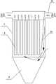
图1是本实用新型实施例一的结构示意图; Fig. 1 is the structural representation of the utility model embodiment one;
图2是本实用新型实施例二的结构示意图; Fig. 2 is the structural representation of the second embodiment of the utility model;
图3是本实用新型实施例三的结构示意图。
Fig. 3 is a schematic structural view of
具体实施方式 Detailed ways
实施例一:如图1所示,一种布袋除尘器箱体侧进风装置,包括布袋除尘器中箱体1及相连的灰斗3,中箱体下部设有下进风口4,并且在中箱体内下进风口与滤袋2之间设置下导流板5,下导流板下端低于中箱体内的滤袋2,使一部分大颗粒烟尘直接落入灰斗中,另一部分烟气从其它方向流向滤袋2,以减少对滤袋的直接冲击。
Embodiment 1: As shown in Figure 1, a side air inlet device for a bag filter box includes a
实施例二:如图2所示,一种布袋除尘器箱体侧进风装置,包括布袋除尘器中箱体1及相连的灰斗3,中箱体上部设有上进风口4a,并且在中箱体内设置上导流板5a与该上进风口配合,上导流板从该上进风口倾斜延伸到滤袋2下方的灰斗处。
Embodiment 2: As shown in Figure 2, a side air inlet device for a bag filter box includes a bag
实施例三:如图3所示,一种布袋除尘器箱体侧进风装置,包括布袋除尘器中箱体1及相连的灰斗3,所述中箱体中部连接一个喇叭状进风口4b,并且在喇叭状进风口内设置至少二个导流板5b与该进风口配合,烟气经过两个导流板5b后均匀流向滤袋2,大颗粒烟尘则直接落入下方的灰斗中。
Embodiment 3: As shown in Figure 3, a side air intake device for a bag filter box, including a
由以上实施例可以看出,本实用新型提供的中箱体侧进风装置,烟气入口在中箱体位置,烟气由入口进入进风烟道,除尘器抽风位置一般位于中箱体的烟道与袋室之间隔板下部,进风风速大多控制在12-15m/s的速度,烟气进入烟道后经由隔板绕流进入除尘器布袋室,大颗粒可进行部分沉降,且进风位置远高于灰斗,不易形成二次扬尘。由于进风口位于箱体侧部,其形状可以设计为细长型,占地面积小,清灰效果显著。 It can be seen from the above examples that, in the side air intake device of the middle box provided by the utility model, the flue gas inlet is at the position of the middle box, and the flue gas enters the air inlet flue from the entrance, and the exhaust position of the dust collector is generally located at the side of the middle box. The lower part of the partition between the flue and the bag room, the wind speed of the air intake is mostly controlled at 12-15m/s. After the flue gas enters the flue, it flows around the partition and enters the bag room of the dust collector. The wind position is much higher than the ash hopper, so it is not easy to form secondary dust. Since the air inlet is located on the side of the box, its shape can be designed as a slender shape, which occupies a small area and has a remarkable cleaning effect.
Claims (4)
Priority Applications (1)
| Application Number | Priority Date | Filing Date | Title |
|---|---|---|---|
| CN2012200305311U CN202497787U (en) | 2012-01-31 | 2012-01-31 | Box side-air inlet device of bag dust collector |
Applications Claiming Priority (1)
| Application Number | Priority Date | Filing Date | Title |
|---|---|---|---|
| CN2012200305311U CN202497787U (en) | 2012-01-31 | 2012-01-31 | Box side-air inlet device of bag dust collector |
Publications (1)
| Publication Number | Publication Date |
|---|---|
| CN202497787U true CN202497787U (en) | 2012-10-24 |
Family
ID=47034416
Family Applications (1)
| Application Number | Title | Priority Date | Filing Date |
|---|---|---|---|
| CN2012200305311U Expired - Fee Related CN202497787U (en) | 2012-01-31 | 2012-01-31 | Box side-air inlet device of bag dust collector |
Country Status (1)
| Country | Link |
|---|---|
| CN (1) | CN202497787U (en) |
Cited By (1)
| Publication number | Priority date | Publication date | Assignee | Title |
|---|---|---|---|---|
| CN108626737A (en) * | 2018-04-12 | 2018-10-09 | 中国神华能源股份有限公司 | For the flue component of boiler system and the boiler system with the flue component |
-
2012
- 2012-01-31 CN CN2012200305311U patent/CN202497787U/en not_active Expired - Fee Related
Cited By (2)
| Publication number | Priority date | Publication date | Assignee | Title |
|---|---|---|---|---|
| CN108626737A (en) * | 2018-04-12 | 2018-10-09 | 中国神华能源股份有限公司 | For the flue component of boiler system and the boiler system with the flue component |
| CN108626737B (en) * | 2018-04-12 | 2019-10-15 | 中国神华能源股份有限公司 | Flue assembly for boiler system and boiler system with the same |
Similar Documents
| Publication | Publication Date | Title |
|---|---|---|
| CN203183837U (en) | Bag type dust remover special for fine particulate matters | |
| CN203971623U (en) | A kind of pulse bag type dust collector wedge shape air inlet duct with guiding device | |
| CN203155026U (en) | Waste gas dust remover | |
| CN104338612A (en) | Airflow uniform distribution device applicable to high-concentration dust collector | |
| CN202751926U (en) | Tandem type static sack composite dust remover | |
| CN203557271U (en) | Polishing and dust removal house | |
| CN204672040U (en) | A kind of pulse bag type dust collector | |
| CN201618490U (en) | A low-resistance and high-efficiency electric bag combined dust collector | |
| CN207126261U (en) | A kind of double air intake resistance bag-type dust removers | |
| CN203227370U (en) | Filter cylinder type dust collection machine | |
| CN202387558U (en) | Dual flow velocity high-efficiency electrostatic precipitator | |
| CN201692747U (en) | Electric-bag composite type dust collector | |
| CN204746642U (en) | Six block form cyclone | |
| CN205288692U (en) | Dust remover smoke box air flow distribution device that admits air | |
| CN203075774U (en) | Flag-bag dust collector | |
| CN102688633A (en) | Improved deduster | |
| CN203990198U (en) | A kind of coal-burning boiler staged electric-bag complex dust collector | |
| CN203829812U (en) | Air inlet smoke box applied to large venting dust remover | |
| CN202289716U (en) | Centrifugal sedimentation type mechanical filter for railway vehicles | |
| CN201997196U (en) | Improved dust remover | |
| CN203281587U (en) | Dust removal system with controllable blast capacity | |
| CN202569835U (en) | Single side air intake type online pulse cleaning bag deduster | |
| CN205287979U (en) | Compound dust remover of pipe bag | |
| CN207872403U (en) | A kind of electrostatic precipitation case | |
| CN202387344U (en) | High-density bag type dust remover |
Legal Events
| Date | Code | Title | Description |
|---|---|---|---|
| C14 | Grant of patent or utility model | ||
| GR01 | Patent grant | ||
| PE01 | Entry into force of the registration of the contract for pledge of patent right |
Denomination of utility model: Box side-air inlet device of bag dust collector Effective date of registration: 20140326 Granted publication date: 20121024 Pledgee: Pudong Development Bank of Shanghai, Limited by Share Ltd, Bengbu branch Pledgor: Anhui Hengyi Environmental Technology Co., Ltd. Registration number: 2014990000205 |
|
| PLDC | Enforcement, change and cancellation of contracts on pledge of patent right or utility model | ||
| PC01 | Cancellation of the registration of the contract for pledge of patent right |
Date of cancellation: 20160816 Granted publication date: 20121024 Pledgee: Pudong Development Bank of Shanghai, Limited by Share Ltd, Bengbu branch Pledgor: Anhui Hengyi Environmental Technology Co., Ltd. Registration number: 2014990000205 |
|
| PLDC | Enforcement, change and cancellation of contracts on pledge of patent right or utility model | ||
| PE01 | Entry into force of the registration of the contract for pledge of patent right |
Denomination of utility model: Box side-air inlet device of bag dust collector Effective date of registration: 20160817 Granted publication date: 20121024 Pledgee: Pudong Development Bank of Shanghai, Limited by Share Ltd, Bengbu branch Pledgor: Anhui Hengyi Environmental Technology Co., Ltd. Registration number: 2016990000664 |
|
| PLDC | Enforcement, change and cancellation of contracts on pledge of patent right or utility model | ||
| CF01 | Termination of patent right due to non-payment of annual fee |
Granted publication date: 20121024 Termination date: 20180131 |
|
| CF01 | Termination of patent right due to non-payment of annual fee |