CN202496778U - lifting and angle adjusting mechanism - Google Patents
lifting and angle adjusting mechanism Download PDFInfo
- Publication number
- CN202496778U CN202496778U CN2012200104011U CN201220010401U CN202496778U CN 202496778 U CN202496778 U CN 202496778U CN 2012200104011 U CN2012200104011 U CN 2012200104011U CN 201220010401 U CN201220010401 U CN 201220010401U CN 202496778 U CN202496778 U CN 202496778U
- Authority
- CN
- China
- Prior art keywords
- linkage part
- plate
- plate body
- fixed
- fixed body
- Prior art date
- Legal status (The legal status is an assumption and is not a legal conclusion. Google has not performed a legal analysis and makes no representation as to the accuracy of the status listed.)
- Expired - Fee Related
Links
- 238000005253 cladding Methods 0.000 claims description 9
- 238000000926 separation method Methods 0.000 claims description 6
- 238000010420 art technique Methods 0.000 description 2
- NHDHVHZZCFYRSB-UHFFFAOYSA-N pyriproxyfen Chemical compound C=1C=CC=NC=1OC(C)COC(C=C1)=CC=C1OC1=CC=CC=C1 NHDHVHZZCFYRSB-UHFFFAOYSA-N 0.000 description 2
- TVEXGJYMHHTVKP-UHFFFAOYSA-N 6-oxabicyclo[3.2.1]oct-3-en-7-one Chemical compound C1C2C(=O)OC1C=CC2 TVEXGJYMHHTVKP-UHFFFAOYSA-N 0.000 description 1
- 238000009825 accumulation Methods 0.000 description 1
- 238000012797 qualification Methods 0.000 description 1
- 238000012827 research and development Methods 0.000 description 1
Images


Landscapes
- Chairs For Special Purposes, Such As Reclining Chairs (AREA)
Abstract
The utility model relates to a lifting and angle adjusting mechanism, which mainly comprises a lower fixing body, an inner fixing body, a sliding sleeve body, a linkage body, a passive unit, a joint body, an upper body and an upper fixing body; the lower fixing body and the inner fixing body are combined into a whole, the sliding sleeve body can move relative to the inner fixing body by utilizing the state change of the linkage body and the passive unit, the upper body and the upper fixing body can be matched with the passive unit to carry out lifting and angle adjustment, and the joint body provides angle adjustment and positioning of the upper body. The utility model can be applied to the headrest and backrest structure of the chair, and can provide the functions of headrest lifting and angle adjustment.
Description
Technical field
The utility model is relevant for a kind of up-down and angle-adjusting mechanism, particularly has to let the headrest of chair tool with respect to the backrest device with the angle adjustment effect that goes up and down.
Background technology
The modern chooses for chair, not only requires to have attractive appearance, to many attention especially of its function.For example many people just focus on the angle adjustment of each structure very much, so that be adapted to the user of different heights, or can cooperate sitting posture and change.
Though the headrest of existing chair tool can carry out the effect of angle adjustment with respect to backrest; But this structure applications is when sofa; Often at the clad place of headrest and backrest handing-over, this clad has the not attractive in appearance existing picture of pile-up, the perhaps only effect of the angle adjustment of tool headrest of the existing chair of other; Can't carry out lift adjustment, make still to be apparent not enough on the function.
In view of this, inventor's ongoing effort research and development, the phase can provide the more structure of innovation again, to satisfy the demand of consumer's seeking change and innovation.The inventor collects related data, and through assessing in many ways and consider, and to engage in the many years of experience of the industry accumulation, via constantly studying and revising, there is the birth of the utility model the beginning.
The utility model content
Up-down of the utility model and angle-adjusting mechanism, its main purpose is: a kind of mechanism is provided, and it can be applied in the chair tool internal structure, and it can let the headrest of chair tool realize going up and down and the angle adjustment purpose with respect to backrest; Whereby, when the user was sitting on the chair tool, headrest can need be adjusted according to self height or sitting posture, to obtain comfortable impression.
Through the enforcement of the utility model up-down with angle-adjusting mechanism, can exempt the headrest of this chair tool and the clad between backrest, more can obtain and not have the pile-up puzzlement of picture at present.
For realizing above-mentioned purpose, the content of the utility model is: this up-down and angle-adjusting mechanism comprise: an interior fixed body; A sliding sleeve body, section is the ㄇ font, and the insied width of this sliding sleeve body is greater than the outer width of interior this fixed body; This sliding sleeve body cover is organized fixed body outer rim in this, and consolidates the body slippage in can being somebody's turn to do relatively;
An interlock body is a plate body, and the bottom of this interlock body is connected with the lateral surface to this sliding sleeve body;
A passive unit comprises one first plate body, second plate body, the 3rd plate body, the 4th plate body, the 5th plate body, the 6th plate body; Wherein these first plate body two ends are respectively equipped with first linkage part and second linkage part; These second plate body two ends are respectively second linkage part and the 4th linkage part; And be provided with the 3rd linkage part between this second linkage part and the 4th linkage part, the 3rd linkage part is positioned at an end of the 3rd plate body again, and the other end of the 3rd plate body is the 5th linkage part; The 5th linkage part is connected to an end of the 4th plate body again; And the 4th plate body other end is the 7th linkage part, and is provided with one the 6th linkage part between the 5th linkage part and the 7th linkage part, and the 7th linkage part is positioned at an end of the 5th plate body; The other end of the 5th plate body is the 8th linkage part, and the 8th linkage part is connected with the 6th plate body again; Place, fixed body top in aforementioned first linkage part is articulated in, and the 4th linkage part and the 6th linkage part are articulated on this interlock body;
This joint body includes two sandwich panels, and this two sandwich panels bottom is marriage relation, and the top of this two sandwich panel is separation relation, and is provided with fluted disc between two sandwich panel tops of this separation shape, and this fluted disc center is placed through this two sandwich panel with an axis body; This joint body is incorporated into an outer edge surface of this interlock body;
This upper body extends from a side of fluted disc and to form, and is a plate body, can form interlock with this fluted disc.
Preferable, fixed body outside is provided with fixed body in this, and its section is a Z-shaped plate sheet, includes a bottom plate and an outer cladding plate, and this outer cladding plate is provided with several joint portions down.Preferable, this interior fixed body, the outer cladding plate that is fixedly arranged on down fixed body is inner, and the joint portion is fixed under utilizing between fixed body and following fixed body in particularly being somebody's turn to do.
Preferable; Should slightly be the ㄇ font by interior fixed body section; Outside, both sides correspondence is provided with internal gasket, roller bearing and outer pad, and this each internal gasket all digs with outer pad and is provided with the pothole that supplies ccontaining roller bearing, and this sliding sleeve body is by this roller bearing and with respect to fixed body slippage in this.
Preferable, a lateral end of this upper body is combined with one and goes up fixed body, is a L shaped plate, includes a joint portion and a upper mounted plate, on this between joint portion and the upper body geometrical clamp be provided with the 6th plate body.
It is inner that up-down of the utility model and angle-adjusting mechanism, this time fixed body are locked in the backrest of sofa, and will go up in the headrest features that fixed body is locked in sofa; On with upper body, moving uprightly, will force passive unit to change state, is fulcrum with the 6th linkage part, the 4th linkage part at first; Make this first plate body, second plate body, the 3rd plate body, the 4th plate body and the 5th plate body all by interlock and expansion; This first linkage part is fixed in interior fixed body, on draw this upper body after, interlock body and sliding sleeve body will upwards be slided with respect to interior fixed body divide a word with a hyphen at the end of a line; Reach the purpose of adjustment height of headrest and angle simultaneously, increase the comfort level of seats such as sofa.
Description of drawings
Fig. 1 is the stereo appearance figure of the utility model.
Stereo appearance figure when Fig. 2 adjusts for the utility model.
Fig. 3 accomplishes adjusted stereo appearance figure for the utility model.
Fig. 4 is implemented on the sketch map in the sofa for the utility model.
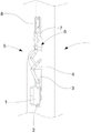
Fig. 4 A is the partial enlarged drawing of meaning structure shown in Figure 4.
The sketch map that Fig. 5 adjusts in the sofa for the utility model is implemented on.
Fig. 6 is implemented on the sketch map of accomplishing adjustment in the sofa for the utility model.
[main element symbol description]
1 time fixed body 11 bottom plates 12 outer cladding plate
Fixed body 21 internal gaskets in 13 times joint portions 2
22 roller bearings, 23 outer pad 3 sliding sleeve bodies
4 interlock bodies, 5 passive units, 51 first plate bodys
511 first linkage part, 52 second plate bodys, 521 second linkage part
522 the 4th linkage part 53 the 3rd plate body 531 the 3rd linkage part
532 the 5th linkage part 533 the 6th linkage part 54 the 4th plate body
55 the 5th plate bodys 551 the 7th linkage part 56 the 6th plate body
561 the 8th linkage part, 6 joint bodies, 61 sandwich panels
62 fluted discs, 63 axis bodies, 7 upper bodies
91 backrests, 92 headrests.
The specific embodiment
Detailed features and preferred embodiment about the utility model; Now conjunction with figs. specifies as follows; Its content is enough to make any related art techniques person of haveing the knack of to understand the technology contents of the utility model and implements according to this; And according to content and the accompanying drawing that this specification disclosed, any related art techniques person of haveing the knack of can understand aforesaid purpose and advantage easily.
The following listed examples of the utility model only is used to explain the purpose and the preferred embodiment of the utility model, is not the scope in order to restriction the utility model.
Head sees also shown in Figure 1; The utility model goes up and down and angle-adjusting mechanism; Mainly comprise in the fixed body 1, a fixed body 8 on fixed body 2, a sliding sleeve body 3, an interlock body 4, a passive unit 5, a joint body 6, the upper body 7 and, wherein:
This time fixed body 1, section are a Z-shaped plate sheet, include a bottom plate 11 and an outer cladding plate 12, and this outer cladding plate 12 is provided with several joint portions 13 down;
Should in fixed body 2, be fixedly arranged on down outer cladding plate 12 inside of fixed body 1, particularly should under fixed body 2 and 1 utilization of following fixed body joint portion 13 fix; Should in fixed body 2 sections slightly be the ㄇ font, outside, its both sides correspondence is provided with internal gasket 21, roller bearing 22 and outer pad 23, this each internal gasket 21 and outer pad 23 (like Fig. 4 and Fig. 4 A) all dig to be provided with to provide and give the ccontaining pothole of roller bearing 22;
This sliding sleeve body 3, section slightly is the ㄇ font, and the insied width of this sliding sleeve body 3 is greater than the outer width of interior fixed body 2; These sliding sleeve body 3 covers are organized in interior fixed body 2 outer rims, and both are preferable with the relative mode of the opening direction group that is nested, and utilize this each roller bearing 22 to cause this sliding sleeve body 3 can be with respect to interior fixed body 2 slippages;
This interlock body 4 is a plate body, and a bottom is connected with the lateral surface to sliding sleeve body 3;
This passive unit 5 comprises one first plate body 51, one second plate body 52, one the 3rd plate body 53, one the 4th plate body 54, one the 5th plate body 55, one the 6th plate body 56; Wherein these first plate body, 51 two ends are respectively equipped with first linkage part 511 and second linkage part 521; These second plate body, 52 two ends are respectively second linkage part 521 and the 4th linkage part 522; And be provided with the 3rd linkage part 531 between this second linkage part 521 and the 4th linkage part 522, the 3rd linkage part 531 is connected in an end of the 3rd plate body 53 again, and the other end of the 3rd plate body 53 is the 5th linkage part 532; The 5th linkage part 532 is connected to an end of the 4th plate body 54 again; And the 4th plate body 54 other ends are the 7th linkage part 551, and are provided with the end that one the 6th linkage part, 533, the seven linkage part 551 are located at the 5th plate body 55 between the 5th linkage part 532 and the 7th linkage part 551; The other end of the 5th plate body 55 is that the 8th linkage part 561, the eight linkage part 561 are connected with the 6th plate body 56 again; Place, fixed body 2 tops in aforementioned first linkage part 511 is articulated in, and the 4th linkage part 522 and the 6th linkage part 533 are articulated on the interlock body 4;
This joint body 6; Include two sandwich panels 61, these two sandwich panels, 61 bottoms are marriage relation, but these two sandwich panels, 61 tops are separation relation; And 61 of two sandwich panels of this separation shape are provided with fluted disc 62, and these fluted disc 62 centers are placed through two sandwich panels 61 by an axis body 63; This joint body 6 is incorporated into an outer edge surface of interlock body 4;
This upper body 7 extends from a side of fluted disc 6 and to form, and is a plate body, can with fluted disc 62 interlocks, be preferably, an end clip of this upper body 7 is in the tooth portion of this fluted disc 6; Perhaps both are one-body molded.
Should go up fixed body 8, in conjunction with being located at upper body 7 one lateral end, be a L shaped plate, includes a joint portion 81 and a upper mounted plate 82, on this between joint portion 81 and the upper body 7 geometrical clamp be provided with the 6th plate body 56.
Shown in Figure 1ly be the state that lies low for the upper body 7 of the utility model.On with upper body 7, move uprightly, will force passive unit 5 change states; At first; With the 6th linkage part 533, the 4th linkage part 522 is fulcrum; Cause this first plate body 51, second plate body 52, the 3rd plate body 53, the 4th plate body 54 and the 5th plate body 55 all by interlock and expansion (like Fig. 2), again because of first linkage part 511 be fixed in fixed body 2, on draw this upper body 7 after; Interlock body 4 and sliding sleeve body 3 will upwards be divided a word with a hyphen at the end of a line with respect to interior fixed body 2, can obtain upright state (like Fig. 3) fully eventually.Then, can make headrest be fixed in the position that certain is adjusted by the engagement of fluted disc 6 with miscellaneous part.
Like Fig. 4, Fig. 5, shown in Figure 6, be the action sketch map of the utility model structure applications in sofa.This time fixed body 1 is locked in backrest 91 inside of sofa, and will goes up in headrest 92 structures that fixed body 8 is locked in sofa, can change in order to rest the head on 92 up-down and angle adjustment.
The above person is merely the embodiment of the utility model, when can not with the scope implemented of qualification the utility model.The equalization of promptly doing according to the utility model generally changes and modifies, and all should still belong in the utility model scope required for protection.
Claims (4)
1. one kind is gone up and down and angle-adjusting mechanism, and its characteristic comprises:
An interior fixed body;
A sliding sleeve body, section is the ㄇ font, and the insied width of this sliding sleeve body is greater than the outer width of interior this fixed body; This sliding sleeve body cover is organized fixed body outer rim in this, and consolidates the body slippage in can being somebody's turn to do relatively;
An interlock body is a plate body, and the bottom of this interlock body is connected with the lateral surface to this sliding sleeve body;
A passive unit comprises one first plate body, second plate body, the 3rd plate body, the 4th plate body, the 5th plate body, the 6th plate body; Wherein these first plate body two ends are respectively equipped with first linkage part and second linkage part; These second plate body two ends are respectively second linkage part and the 4th linkage part; And be provided with the 3rd linkage part between this second linkage part and the 4th linkage part, the 3rd linkage part is positioned at an end of the 3rd plate body again, and the other end of the 3rd plate body is the 5th linkage part; The 5th linkage part is connected to an end of the 4th plate body again; And the 4th plate body other end is the 7th linkage part, and is provided with one the 6th linkage part between the 5th linkage part and the 7th linkage part, and the 7th linkage part is positioned at an end of the 5th plate body; The other end of the 5th plate body is the 8th linkage part, and the 8th linkage part is connected with the 6th plate body again; Aforementioned first linkage part is articulated in place, fixed body top in this, and the 4th linkage part and the 6th linkage part are articulated on this interlock body;
This joint body includes two sandwich panels, and this two sandwich panels bottom is marriage relation, and the top of this two sandwich panel is separation relation, and is provided with fluted disc between two sandwich panel tops of this separation shape, and this fluted disc center is placed through this two sandwich panel with an axis body; This joint body is incorporated into an outer edge surface of this interlock body;
This upper body extends from a side of fluted disc and to form, and is a plate body, can form interlock with this fluted disc.
2. up-down as claimed in claim 1 and angle-adjusting mechanism; It is characterized in that: fixed body outside is provided with fixed body in this; This time fixed body, section are a Z-shaped plate sheet, and it includes a bottom plate and an outer cladding plate; Should be provided with several joint portions down by outer cladding plate, fix by this time joint portion between fixed body and following fixed body in this.
3. up-down as claimed in claim 1 and angle-adjusting mechanism; It is characterized in that: fixed body section is the ㄇ font in this; Outside, both sides correspondence is provided with internal gasket, roller bearing and outer pad; This each internal gasket digs with outer pad and is provided with the pothole that supplies ccontaining this roller bearing, and this sliding sleeve body is by this roller bearing and with respect to fixed body slippage in this.
4. up-down as claimed in claim 1 and angle-adjusting mechanism; It is characterized in that: a lateral end of this upper body is combined with one and goes up fixed body; Should go up fixed body is a L shaped plate; Include joint portion and upper mounted plate, on this between joint portion and the upper body geometrical clamp establish the 6th plate body.
Priority Applications (1)
| Application Number | Priority Date | Filing Date | Title |
|---|---|---|---|
| CN2012200104011U CN202496778U (en) | 2012-01-11 | 2012-01-11 | lifting and angle adjusting mechanism |
Applications Claiming Priority (1)
| Application Number | Priority Date | Filing Date | Title |
|---|---|---|---|
| CN2012200104011U CN202496778U (en) | 2012-01-11 | 2012-01-11 | lifting and angle adjusting mechanism |
Publications (1)
| Publication Number | Publication Date |
|---|---|
| CN202496778U true CN202496778U (en) | 2012-10-24 |
Family
ID=47033416
Family Applications (1)
| Application Number | Title | Priority Date | Filing Date |
|---|---|---|---|
| CN2012200104011U Expired - Fee Related CN202496778U (en) | 2012-01-11 | 2012-01-11 | lifting and angle adjusting mechanism |
Country Status (1)
| Country | Link |
|---|---|
| CN (1) | CN202496778U (en) |
-
2012
- 2012-01-11 CN CN2012200104011U patent/CN202496778U/en not_active Expired - Fee Related
Similar Documents
| Publication | Publication Date | Title |
|---|---|---|
| CN201659907U (en) | Vehicle seat and seat back | |
| JP2014036730A (en) | Vehicle seat | |
| JP2007515981A (en) | Seat part of seat | |
| CN201595481U (en) | Splicing structure of combination sofa | |
| CN202496778U (en) | lifting and angle adjusting mechanism | |
| CN103921702B (en) | A kind of sleeping support on the chair back | |
| CN212889998U (en) | Special heating device for automobile seat | |
| CN2432105Y (en) | Dual-purpose seat for sitting and sleeping for passenger carriage | |
| CN205344599U (en) | Can be according to four seasons seatpad that freely alternaties season | |
| CN201923193U (en) | Seat mechanism and baby trolley provided with same | |
| CN201542850U (en) | Adjustable backrest assembly of luxury wheelchair with reclining back | |
| CN203090380U (en) | Golf cart seat | |
| JP7273885B2 (en) | Seat support drive and support assembly including the same | |
| CN201303760Y (en) | Novel sofa bed | |
| CN208827645U (en) | Auto use chair easily enters the control crank mounting base of system | |
| CN212213177U (en) | Multifunctional tool stool | |
| CN207089538U (en) | The mounting structure of fuel tank afterbody and straddle car | |
| CN207388978U (en) | The seat for long-distance vehicle that a kind of omnidirection is adjusted | |
| JP2016166018A (en) | Vehicle seat | |
| CN206264841U (en) | Car Cushion | |
| CN202038203U (en) | Rattan surface type automobile seat cushion | |
| CN206621099U (en) | A kind of farm office multifunction seat | |
| CN211154724U (en) | Variable twin bed's sofa of being sat up | |
| CN201849557U (en) | Cushion for bicycle backseat | |
| CN201171499Y (en) | Folding chair |
Legal Events
| Date | Code | Title | Description |
|---|---|---|---|
| C14 | Grant of patent or utility model | ||
| GR01 | Patent grant | ||
| CF01 | Termination of patent right due to non-payment of annual fee |
Granted publication date: 20121024 Termination date: 20150111 |
|
| EXPY | Termination of patent right or utility model |