CN202496599U - Pencil case opened and closed bilaterally forwards and backwards - Google Patents
Pencil case opened and closed bilaterally forwards and backwards Download PDFInfo
- Publication number
- CN202496599U CN202496599U CN2012200181431U CN201220018143U CN202496599U CN 202496599 U CN202496599 U CN 202496599U CN 2012200181431 U CN2012200181431 U CN 2012200181431U CN 201220018143 U CN201220018143 U CN 201220018143U CN 202496599 U CN202496599 U CN 202496599U
- Authority
- CN
- China
- Prior art keywords
- connecting rod
- box body
- lid
- box
- right connecting
- Prior art date
- Legal status (The legal status is an assumption and is not a legal conclusion. Google has not performed a legal analysis and makes no representation as to the accuracy of the status listed.)
- Expired - Fee Related
Links
- 230000000694 effects Effects 0.000 abstract description 4
- 230000002457 bidirectional effect Effects 0.000 abstract description 3
- 238000000034 method Methods 0.000 abstract description 3
- 238000010586 diagram Methods 0.000 description 4
Images


Landscapes
- Purses, Travelling Bags, Baskets, Or Suitcases (AREA)
Abstract
本实用新型涉及文具盒结构技术领域,具体地说是涉及一种可前后双向开闭的文具盒,包括盒体和盒盖,盒体与盒盖之间至少采用一根左连接杆和一根右连接杆活动连接,左连接杆前端与盒盖前侧铰链,后端与盒体后侧铰链;右连接杆后端与盒盖后侧铰链,前端与盒体前侧铰链,采用本技术方案,当闭合的盒盖相对盒体向后打开时,盒盖以左连接杆后端与盒体后侧铰链处以及右连接杆与盒盖后侧铰链处为旋转支点进行右旋转;当闭合的盒盖相对盒体向前打开时,盒盖以右连接杆前端与盒体前侧铰链处以及左连接杆与盒盖前侧铰链处为旋转支点进行前旋转,关文具盒的过程正好相反。这样,就能实现和解决前后双向开闭的技术问题,达到使用方便的效果。
The utility model relates to the technical field of stationery box structure, in particular to a stationery box which can be opened and closed in both directions, including a box body and a box cover, at least one left connecting rod and one The right connecting rod is movably connected, the front end of the left connecting rod is hinged with the front side of the box cover, and the rear end is hinged with the rear side of the box body; the rear end of the right connecting rod is hinged with the rear side of the box cover, and the front end is hinged with the front side of the box body. This technical solution is adopted , when the closed lid is opened backward relative to the box body, the lid rotates to the right with the hinges between the rear end of the left connecting rod and the rear side of the box body and the hinges between the right connecting rod and the rear side of the box cover; when the closed When the lid is opened forward relative to the box body, the lid rotates forward with the front hinge of the right connecting rod and the front hinge of the box body and the hinge of the left connecting rod and the front of the lid. The process of closing the pencil case is just the opposite. In this way, the technical problem of front and rear bidirectional opening and closing can be realized and solved, and the effect of convenient use can be achieved.
Description
技术领域 technical field
本实用新型涉及文具盒结构技术领域,具体地说是涉及一种可前后双向开闭的文具盒。 The utility model relates to the technical field of stationery box structure, in particular to a stationery box which can be opened and closed bidirectionally.
背景技术 Background technique
目前,市场上中小学生使用的文具盒,在使用时存在反向无法打开的弊端,即只能朝着一个方向将文具盒打开,不能前后双向打开,在使用时,存在一些不方便。 At present, the stationery boxes used by primary and middle school students on the market have the disadvantage that they cannot be opened in reverse, that is, the stationery boxes can only be opened in one direction, and cannot be opened in both directions, which is inconvenient in use.
发明内容 Contents of the invention
本实用新型要解决的技术问题是提供一种可前后双向开闭的文具盒,简单有效的解决前后双向开闭的技术问题。 The technical problem to be solved by the utility model is to provide a writing case that can be opened and closed bidirectionally, which simply and effectively solves the technical problem of bidirectional opening and closing.
为了解决上述技术问题,本实用新型提供的一种可前后双向开闭的文具盒,包括盒体和盒盖,盒体与盒盖之间至少采用一根左连接杆和一根右连接杆活动连接,左连接杆前端与盒盖前侧铰链,后端与盒体后侧铰链;右连接杆后端与盒盖后侧铰链,前端与盒体前侧铰链。 In order to solve the above technical problems, the utility model provides a stationery box that can be opened and closed in both directions, including a box body and a box cover. At least one left connecting rod and one right connecting rod are used to move between the box body and the box cover. Connect, the front end of the left connecting rod is hinged with the front side of the box cover, and the rear end is hinged with the rear side of the box body; the rear end of the right connecting rod is hinged with the rear side of the box cover, and the front end is hinged with the front side of the box body.
上述技术方案中,由于盒体与盒盖之间至少采用一根左连接杆和一根右连接杆活动连接,左连接杆前端与盒盖前侧铰链,后端与盒体后侧铰链;右连接杆后端与盒盖后侧铰链,前端与盒体前侧铰链,采用这种盒盖结构,当闭合的盒盖相对盒体向后打开时,盒盖以左连接杆后端与盒体后侧铰链处以及右连接杆与盒盖后侧铰链处为旋转支点进行右旋转,此时,右连接杆紧贴盒体保持不动,左连接杆紧贴盒盖随着盒盖一起后旋转;当闭合的盒盖相对盒体向前打开时,盒盖以右连接杆前端与盒体前侧铰链处以及左连接杆与盒盖前侧铰链处为旋转支点进行前旋转,此时,左连接杆紧贴盒体保持不动,右连接杆紧贴盒盖随着盒盖一起左旋转;关文具盒的过程正好相反。这样,就能实现和解决前后双向开闭的技术问题,达到使用方便,可以任意前后打开盒盖的效果,具有简单有效,不受摆放位置限制的优点。 In the above-mentioned technical scheme, since at least one left connecting rod and one right connecting rod are movably connected between the box body and the box cover, the front end of the left connecting rod is hinged with the front side of the box cover, and the rear end is hinged with the rear side of the box body; The rear end of the connecting rod is hinged with the rear side of the box cover, and the front end is hinged with the front side of the box body. With this cover structure, when the closed box cover is opened backward relative to the box body, the box cover is connected to the box body with the rear end of the left connecting rod. The rear hinge and the right connecting rod and the rear hinge of the box cover are the fulcrums for right rotation. At this time, the right connecting rod is close to the box body and remains still, and the left connecting rod is close to the box cover and rotates together with the box cover. ; when the closed lid is opened forward relative to the box body, the lid is rotated forward with the front hinge of the right connecting rod and the front hinge of the box body and the hinge of the left connecting rod and the front of the lid. At this time, the left The connecting rod is close to the box body and remains motionless, and the right connecting rod is close to the lid and rotates left together with the lid; the process of closing the pencil case is just the opposite. Like this, just can realize and solve the technical problem of front and back two-way opening and closing, reach the effect of being easy to use, can open front and back arbitrarily, have simple and effective, the advantage that is not restricted by placement position.
进一步,限定所述的左连接杆和右连接杆分别为两根,且左连接杆和右连接杆等长,在盒盖与盒体闭合时,左连接杆和右连接杆呈平行性布置。限制所述的左连接杆和右连接杆等长,在盒盖与盒体闭合时,左连接杆和右连接杆呈平行布置,这样的限制设计,保证了双开文具盒中左、右连杆的对称性设置,使前后开闭时的力度相同。 Further, it is defined that the left connecting rod and the right connecting rod are respectively two, and the left connecting rod and the right connecting rod are equal in length, and when the lid and the box body are closed, the left connecting rod and the right connecting rod are arranged in parallel. Limit the equal length of the left connecting rod and the right connecting rod. When the lid and the box body are closed, the left connecting rod and the right connecting rod are arranged in parallel. Such a restrictive design ensures that the left and right connecting rods in the double-open pencil case The symmetry setting makes the front and rear open and close with the same strength.
总而言之,相对原有的结构设计,本技术方案的文具盒,能实现简单有效的解决前后双向开闭的技术问题,达到使用方便,可以任意前后打开盒盖的效果,使用时,不必考虑摆放位置限制。 All in all, compared with the original structural design, the pencil case of this technical solution can simply and effectively solve the technical problem of bidirectional opening and closing at the front and back, and achieve the effect of being easy to use, and the box cover can be opened back and forth arbitrarily. Location restrictions.
附图说明 Description of drawings
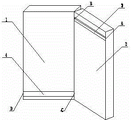
图1是本实用新型一种可前后双向开闭的文具盒实施例一中,当闭合的盒盖相对盒体向后打开时的示意图; Fig. 1 is a schematic diagram of a stationery box that can be opened and closed bidirectionally in the front and rear of the present invention, when the closed lid is opened backward relative to the box body;
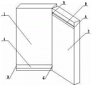
图2是本实用新型一种可前后双向开闭的文具盒实施例一中,当闭合的盒盖相对盒体向前打开时的示意图; Fig. 2 is a schematic diagram of a stationery box that can be opened and closed bidirectionally in the front and rear of the present invention, when the closed lid is opened forward relative to the box body;
图3是本实用新型一种可前后双向开闭的文具盒实施例二中,当闭合的盒盖相对盒体向后打开时的示意图; Fig. 3 is a schematic diagram of a stationery box that can be opened and closed bidirectionally in the front and rear of the present invention, when the closed lid is opened backward relative to the box body;
图4是本实用新型一种可前后双向开闭的文具盒实施例二中,当闭合的盒盖相对盒体向前打开时的示意图; Fig. 4 is a schematic diagram of a stationery box that can be opened and closed bidirectionally in the front and rear of the present invention, when the closed lid is opened forward relative to the box body;
图5是实施例中连接杆与盒体、盒盖处的铰链结构放大的示意图。 Fig. 5 is an enlarged schematic view of the connecting rod and the hinge structure at the box body and box cover in the embodiment.
具体实施方式 Detailed ways
下面结合附图和对本实用新型技术方案进一步说明: Below in conjunction with accompanying drawing and technical scheme of the utility model is further described:
本实用新型一种可前后双向开闭的文具盒实施例一,这种可前后双向开闭的文具盒,如图1、图2及图5所示,包括盒体1和盒盖2,盒体1与盒盖2之间采用一根左连接杆3和一根右连接杆4活动连接,左连接杆3和右连接杆4等长,左连接杆3前端与盒盖前侧A处铰链,左连接杆3后端与盒体后侧B处铰链;右连接杆4后端与盒盖2后侧C处铰链,右连接杆4前端与盒体1前侧D处铰链。在如图1所示的盒盖2相对盒盖1框向后打开状态时,盒盖2以左连接杆3后端与盒体1后侧铰链处(B处)以及右连接杆4与盒盖2后侧铰链处(C处)为旋转支点进行左、右旋转,此时,右连接杆4紧贴盒体1保持不动,左连接杆3紧贴盒盖2随着盒盖2一起左、右旋转;在如图2所示的盒盖2相对盒盖1框向前打开状态时,盒盖2以右连接杆4前端与盒体1前侧铰链处(D处)以及左连接杆3与盒盖2前侧铰链处(A处)为旋转支点进行左、右旋转,此时,左连接杆3紧贴盒体1保持不动,右连接杆4紧贴盒盖2随着盒盖2一起左、右旋转;A/B/C/D处的铰链的结构可以采用多种铰链方式,在本实施例中,采用的是如图5所示的轴套相互铰链的方式,即铰链轴6固定在盒体1和盒盖2的左、后侧边上,铰链套7设置在左连接杆3和右连接杆4的左、右两端,铰链套7活套在铰链轴6上。
Embodiment 1 of a stationery box that can be opened and closed bidirectionally in the front and back of the utility model. This stationery box that can be opened and closed in both directions in the front and back, as shown in Fig. 1, Fig. A left connecting
本实用新型一种可前后双向开闭的文具盒实施例二,这种可前后双向开闭的文具盒,如图3、图4及图5所示,包括盒体1和盒盖2,盒体1与盒盖2之间采用二根左连接杆3和二根右连接杆4活动连接,左连接杆3和右连接杆4等长,其中一根左连接杆3和一根右连接杆4组合设置在盒盖2的上段,另一根左连接杆3和另一根右连接杆4组合设置在盒盖2的下段,这两组连接杆上下对称性设置在文具盒上,在文具盒关闭时,左连接杆3和右连接杆4呈平行性布置,两根左连接杆3前端与盒盖前侧A1处、A2处铰链,左连接杆3后端与盒体后侧B1处、B2处铰链;右连接杆4后端与盒盖2后侧C1处、C2处铰链,右连接杆4前端与盒体1前侧D1处、D2处铰链。在如图3所示的盒盖2相对盒盖1框向后打开状态时,盒盖2以左连接杆3后端与盒体1后侧铰链处(B1处、B2处)以及右连接杆4与盒盖2后侧铰链处(C1处、C2处)为旋转支点进行左、右旋转,此时,右连接杆4紧贴盒体1保持不动,左连接杆3紧贴盒盖2随着盒盖2一起左、右旋转;在如图2所示的盒盖2相对盒盖1框向前打开状态时,盒盖2以右连接杆4前端与盒体1前侧铰链处(D1处、D2处)以及左连接杆3与盒盖2前侧铰链处(A1处、A2处)为旋转支点进行左、右旋转,此时,左连接杆3紧贴盒体1保持不动,右连接杆4紧贴盒盖2随着盒盖2一起左、右旋转;A1、B1、C1、D1、A2、B2、C2、D2处的铰链的结构可以采用多种铰链方式,在本实施例中,采用的是如图5所示的轴套相互铰链的方式,即铰链轴6固定在盒体1和盒盖2的左、后侧边上,铰链套7设置在左连接杆3和右连接杆4的左、右两端,铰链套7活套在铰链轴6上。
需要说明的是,本实用新型还有多种实施方式,可以采用多种铰链连接方式,在此不一一详述。对于本领域的技术人员来说,在不脱离本实用新型结构的前提下,还可以作出若干变形和改进,这些也应该视为本实用新型的保护范围,这些都不会影响本实用新型实施的效果和专利的实用性。 It should be noted that the utility model also has various implementation modes, and various hinge connection modes can be adopted, which will not be described in detail here. For those skilled in the art, under the premise of not departing from the structure of the utility model, some deformations and improvements can also be made, which should also be regarded as the protection scope of the utility model, and these will not affect the implementation of the utility model Effects and utility of patents.
Claims (2)
- One kind can before and after the writing case of double action opening and closing; Comprise box body and lid; It is characterized in that: adopt a left connecting rod and a right connecting rod to flexibly connect left connecting rod front end and lid front side hinge, rear end and box body rear side hinge between box body and the lid at least; Right connecting rod rear end and lid rear side hinge, front end and box body front side hinge.
- 2. according to claim 1 can before and after the writing case of double action opening and closing; It is characterized in that: described left connecting rod and right connecting rod are respectively two; And left connecting rod and right connecting rod are isometric, and when lid and box body closure, left connecting rod and right connecting rod are collimation and arrange.
Priority Applications (1)
| Application Number | Priority Date | Filing Date | Title |
|---|---|---|---|
| CN2012200181431U CN202496599U (en) | 2012-01-16 | 2012-01-16 | Pencil case opened and closed bilaterally forwards and backwards |
Applications Claiming Priority (1)
| Application Number | Priority Date | Filing Date | Title |
|---|---|---|---|
| CN2012200181431U CN202496599U (en) | 2012-01-16 | 2012-01-16 | Pencil case opened and closed bilaterally forwards and backwards |
Publications (1)
| Publication Number | Publication Date |
|---|---|
| CN202496599U true CN202496599U (en) | 2012-10-24 |
Family
ID=47033237
Family Applications (1)
| Application Number | Title | Priority Date | Filing Date |
|---|---|---|---|
| CN2012200181431U Expired - Fee Related CN202496599U (en) | 2012-01-16 | 2012-01-16 | Pencil case opened and closed bilaterally forwards and backwards |
Country Status (1)
| Country | Link |
|---|---|
| CN (1) | CN202496599U (en) |
-
2012
- 2012-01-16 CN CN2012200181431U patent/CN202496599U/en not_active Expired - Fee Related
Similar Documents
| Publication | Publication Date | Title |
|---|---|---|
| CN204797227U (en) | Director's chair | |
| CN202496599U (en) | Pencil case opened and closed bilaterally forwards and backwards | |
| CN204348765U (en) | A kind of accumulator box guide rail docking structure | |
| CN201172499Y (en) | Open the convenient box | |
| CN208784067U (en) | A kind of two-part unlatching cabinet | |
| CN210708658U (en) | An everted overflow box | |
| CN202574306U (en) | Special carrier for library | |
| CN201775336U (en) | Bed with foldable bed table | |
| CN203254811U (en) | A compound folder structure | |
| CN205959472U (en) | Mainframe box is used in computer teaching demonstration | |
| CN201205834Y (en) | Portable pen bag | |
| CN207140613U (en) | A kind of folding document folder for law teaching | |
| CN203016257U (en) | Dustproof bookshelf | |
| CN207657456U (en) | A kind of novel office notepad box | |
| CN205097744U (en) | Special bill case of financial affairs | |
| CN104533197B (en) | Slide rail type hinge | |
| CN203392484U (en) | Device for gripping capacitance | |
| CN203796041U (en) | Multifunctional hinge | |
| CN209719007U (en) | Locking books | |
| CN203467947U (en) | Horizontal-push desktop used for multimedia platform | |
| CN203457947U (en) | Calligraphy and painting tool box | |
| CN203344536U (en) | File box convenient for extracting files | |
| CN202552968U (en) | Clothes rail fixing part and chest using the same | |
| CN209073756U (en) | A kind of vertical filing appliance for financial accounting information management | |
| CN201793101U (en) | Sealing bag |
Legal Events
| Date | Code | Title | Description |
|---|---|---|---|
| C14 | Grant of patent or utility model | ||
| GR01 | Patent grant | ||
| C17 | Cessation of patent right | ||
| CF01 | Termination of patent right due to non-payment of annual fee |
Granted publication date: 20121024 Termination date: 20140116 |