CN202494935U - Device for controlling liquid level - Google Patents

Device for controlling liquid level Download PDF

Info

Publication number
CN202494935U
CN202494935U CN2012200689773U CN201220068977U CN202494935U CN 202494935 U CN202494935 U CN 202494935U CN 2012200689773 U CN2012200689773 U CN 2012200689773U CN 201220068977 U CN201220068977 U CN 201220068977U CN 202494935 U CN202494935 U CN 202494935U
Authority
CN
China
Prior art keywords
liquid level
level gauge
tank diameter
fork type
stirring tank
Prior art date
Legal status (The legal status is an assumption and is not a legal conclusion. Google has not performed a legal analysis and makes no representation as to the accuracy of the status listed.)
Expired - Fee Related
Application number
CN2012200689773U
Other languages
Chinese (zh)
Inventor
施启迪
Current Assignee (The listed assignees may be inaccurate. Google has not performed a legal analysis and makes no representation or warranty as to the accuracy of the list.)
GREAT WORLD INK & PAINT CO., LTD.
Original Assignee
GREAT WORLD INK & PAINT Co Ltd
Priority date (The priority date is an assumption and is not a legal conclusion. Google has not performed a legal analysis and makes no representation as to the accuracy of the date listed.)
Filing date
Publication date
Application filed by GREAT WORLD INK & PAINT Co Ltd filed Critical GREAT WORLD INK & PAINT Co Ltd
Priority to CN2012200689773U priority Critical patent/CN202494935U/en
Application granted granted Critical
Publication of CN202494935U publication Critical patent/CN202494935U/en
Anticipated expiration legal-status Critical
Expired - Fee Related legal-status Critical Current

Links

Images

Landscapes

  • Measurement Of Levels Of Liquids Or Fluent Solid Materials (AREA)

Abstract

The utility model discloses a device for controlling liquid level. The device for controlling the liquid level is arranged on a stirring tank; a top portion of the stirring tank is provided with a guide tube communicating with the inner portion of the stirring tank; one end of the guide tube is provided with a pump; a flow gauge with set predetermined numerical values is arranged on the guide tube; the device for controlling the liquid level comprises an ultrasonic liquid level gauge, a tuning fork type liquid level gauge and a programmable logic controller; the pump is connected with the programmable logic controller; the ultrasonic liquid level gauge and the tuning fork type liquid level gauge are respectively installed on a top portion of the stirring tank and extend into the stirring tank; the distance between a bottom portion of the tuning fork type liquid level gauge and a bottom portion of the stirring tank is smaller than the distance between a bottom portion of the ultrasonic liquid level gauge and the bottom portion of the stirring tank; and the tuning fork type liquid level gauge and the ultrasonic liquid level gauge are respectively connected with the programmable logic controller. The device for controlling the liquid level provide by the utility model can guarantee that a liquid in the stirring tank will not overflow from the stirring tank even if personnel do not handle with the stirring tank which has issued alarm.

Description

Fluid level control device
Technical field
The utility model relates to a kind of fluid level control device.
Background technology
Printing ink is in forming process; Just the prescription of printing ink and liquid ink resin fully mix in tank diameter; Existing tank diameter is sent into liquid in the tank diameter with pumping after the robotization flowmeter is set required flow, though the flow control that flows in the tank diameter has been got well; But can't precisely detect liquid level at the groove inner height; In case because operating personnel set the error of the careless mistake or the flowmeter fault of flow, then can cause liquid flooding to groove, to cause damage or contaminated environment, also influence the quality of product simultaneously.
The utility model content
The purpose of the utility model is the deficiency to above-mentioned prior art, provides a kind of and can prevent the fluid level control device of liquid flooding to tank diameter.
The technical scheme of the utility model is achieved in that a kind of fluid level control device; Said fluid level control device is installed on the tank diameter; The top of said tank diameter is provided with the conduit with the internal communication of tank diameter; One end of said conduit is provided with pumping; The flowmeter of setting predetermined value is installed on the said conduit; Said fluid level control device comprises ultrasonic liquid level gauge, tuning-fork type liquid level gauge and programmable logic controller (PLC), and said pumping is connected with programmable logic controller (PLC), and said ultrasonic liquid level gauge, tuning-fork type liquid level gauge are installed in the top of said tank diameter respectively and stretch in the said tank diameter; The length of said tuning-fork type liquid level gauge distance from bottom tank diameter bottom is less than the length of said ultrasonic liquid level gauge distance from bottom tank diameter bottom, and said tuning-fork type liquid level gauge, ultrasonic liquid level gauge are connected with said programmable logic controller (PLC) respectively.
Preferably, the length at the top of the said tank diameter of distance from bottom of said tuning-fork type liquid level gauge is 10-15cm.
Preferably, said ultrasonic liquid level gauge is positioned at the center at said tank diameter top.
Preferably, the demonstration control instrument is installed on the said tank diameter, said demonstration control instrument is connected with said tuning-fork type liquid level gauge, ultrasonic liquid level gauge respectively.
The utility model advantage is: ultrasonic liquid level gauge, tuning-fork type liquid level gauge are installed in the top at tank diameter; Can detect the height of liquid in the tank diameter, the mixed liquor in tank diameter surpasses the tuning-fork type liquid level gauge, then can give the alarm; Mixed liquor in tank diameter surpasses the ultrasonic liquid level gauge; Then the PLC controls pumping stops to tank diameter input liquid, even like this because personnel do not deal with the tank diameter that gives the alarm, can guarantee that also the liquid that can not in the tank diameter overflows tank diameter.
Description of drawings
Below in conjunction with the embodiment in the accompanying drawing the utility model is done further to specify, but do not constitute any restriction the utility model.
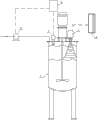
Fig. 1 is the head synoptic diagram of present embodiment.
Embodiment
Below in conjunction with accompanying drawing the preferred embodiment of the utility model is set forth in detail, thereby the protection domain of the utility model is made more explicit defining so that advantage of the utility model and characteristic can be easier to it will be appreciated by those skilled in the art that.
Consult shown in Figure 1; The technical scheme of present embodiment is achieved in that a kind of fluid level control device; Fluid level control device is installed on the tank diameter 1, and the top of tank diameter 1 is provided with the conduit with the internal communication of tank diameter 1, and an end of conduit is provided with pumping 6; The flowmeter of setting predetermined value is installed on the conduit; Fluid level control device comprises ultrasonic liquid level gauge 2, tuning-fork type liquid level gauge 3 and programmable logic controller (PLC) 5, and pumping 6 is connected with programmable logic controller (PLC) 5, and ultrasonic liquid level gauge 2, tuning-fork type liquid level gauge 3 are installed in the top of tank diameter 1 respectively and stretch in the tank diameter 1; The length of tuning-fork type liquid level gauge 3 distance from bottom tank diameters 1 bottom is less than the length of ultrasonic liquid level gauge 2 distance from bottom tank diameters 1 bottom, and tuning-fork type liquid level gauge 3, ultrasonic liquid level gauge 2 are connected with programmable logic controller (PLC) 5 respectively.
The length at the top of the distance from bottom tank diameter 1 of the tuning-fork type liquid level gauge 3 of present embodiment is 10-15cm, and ultrasonic liquid level gauge 2 is positioned at the center at tank diameter 1 top.
Demonstration control instrument 4 is installed on the tank diameter 1 in the present embodiment, shows that control instrument 4 is connected with tuning-fork type liquid level gauge 3, ultrasonic liquid level gauge 2 respectively, show that control instrument 4 is used to show the liquid level in the tank diameter 1.
After pumping 6 got in the tank diameter 1 by programmable logic controller (PLC) 5 control startups, the liquid level in the tank diameter 1 can slowly rise to the liquid level that flowmeter sets, behind the numerical value of setting on the arrival flowmeter; Pumping 6 can stop input liquid ink resin in tank diameter automatically, shows that control instrument 4 shows liquid level in the tank diameter 1, if flowmeter control is not normal; Liquid in the tank diameter 1 can surpass predetermined altitude, when liquid rises to tuning-fork type liquid level gauge 3 lower ends, shows that then control instrument 4 can send ultra level alarm; And when the untimely processing of operating personnel tank diameter 1; Liquid level can slowly rise to the bottom of ultrasonic liquid level gauge 2 again, and in a single day ultrasonic liquid level gauge 2 bottoms touch liquid, then can transmit a stop signal and give programmable logic controller (PLC) 5; Programmable logic controller (PLC) 5 control pumpings 6 stop in tank diameter 1, to carry the liquid ink resin; Such control safeguard measure just can not make the liquid resin in the tank diameter 1 excessive, thereby environmental pollution has reduced unnecessary loss.
Above embodiment is only for explaining the technical conceive and the characteristics of the utility model; Its purpose is to let the people that is familiar with this technology understand the content of the utility model and implements; Can not limit the protection domain of the utility model with this; All equivalences of being done according to the utility model spirit change or modify, and all should be encompassed in the protection domain of the utility model.

Claims (4)

1. fluid level control device; Said fluid level control device is installed on the tank diameter; The top of said tank diameter is provided with the conduit with the internal communication of tank diameter; One end of said conduit is provided with pumping, and the flowmeter of setting predetermined value is installed on the said conduit, and it is characterized in that: said fluid level control device comprises ultrasonic liquid level gauge, tuning-fork type liquid level gauge and programmable logic controller (PLC); Said pumping is connected with programmable logic controller (PLC); Said ultrasonic liquid level gauge, tuning-fork type liquid level gauge are installed in the top of said tank diameter respectively and stretch in the said tank diameter, and the length of said tuning-fork type liquid level gauge distance from bottom tank diameter bottom is less than the length of said ultrasonic liquid level gauge distance from bottom tank diameter bottom, and said tuning-fork type liquid level gauge, ultrasonic liquid level gauge are connected with said programmable logic controller (PLC) respectively.
2. fluid level control device according to claim 1 is characterized in that: the length at the top of the said tank diameter of distance from bottom of said tuning-fork type liquid level gauge is 10-15cm.
3. fluid level control device according to claim 1 is characterized in that: said ultrasonic liquid level gauge is positioned at the center at said tank diameter top.
4. fluid level control device according to claim 1 is characterized in that: the demonstration control instrument is installed on the said tank diameter, and said demonstration control instrument is connected with said tuning-fork type liquid level gauge, ultrasonic liquid level gauge respectively.
CN2012200689773U 2012-02-28 2012-02-28 Device for controlling liquid level Expired - Fee Related CN202494935U (en)

Priority Applications (1)

Application Number Priority Date Filing Date Title
CN2012200689773U CN202494935U (en) 2012-02-28 2012-02-28 Device for controlling liquid level

Applications Claiming Priority (1)

Application Number Priority Date Filing Date Title
CN2012200689773U CN202494935U (en) 2012-02-28 2012-02-28 Device for controlling liquid level

Publications (1)

Publication Number Publication Date
CN202494935U true CN202494935U (en) 2012-10-17

Family

ID=47001153

Family Applications (1)

Application Number Title Priority Date Filing Date
CN2012200689773U Expired - Fee Related CN202494935U (en) 2012-02-28 2012-02-28 Device for controlling liquid level

Country Status (1)

Country Link
CN (1) CN202494935U (en)

Cited By (3)

* Cited by examiner, † Cited by third party
Publication number Priority date Publication date Assignee Title
CN104034488A (en) * 2014-05-27 2014-09-10 燕京啤酒(玉林)有限公司 Leakage preventing detection mechanism of candle type machine cone base
CN104298264A (en) * 2014-11-03 2015-01-21 北京憶众联创电气科技有限公司 Anti-foaming liquid level detecting instrument
CN105928589A (en) * 2016-07-11 2016-09-07 安徽升隆电气有限公司 Ultrasonic radar material level meter

Cited By (4)

* Cited by examiner, † Cited by third party
Publication number Priority date Publication date Assignee Title
CN104034488A (en) * 2014-05-27 2014-09-10 燕京啤酒(玉林)有限公司 Leakage preventing detection mechanism of candle type machine cone base
CN104034488B (en) * 2014-05-27 2016-07-06 燕京啤酒(玉林)有限公司 Candle Shi Jizhuidi anti-leak testing agency
CN104298264A (en) * 2014-11-03 2015-01-21 北京憶众联创电气科技有限公司 Anti-foaming liquid level detecting instrument
CN105928589A (en) * 2016-07-11 2016-09-07 安徽升隆电气有限公司 Ultrasonic radar material level meter

Similar Documents

Publication Publication Date Title
CN203556164U (en) Antifoaming agent adding device
CN205015063U (en) Liquid level calibrating device and liquid level measurement system
CN201386130Y (en) Rare earth extraction and separation production automatic control device
CN106378054A (en) Liquid mixing device
CN203148509U (en) Negative pressure chamber voltage stabilizer of differential pressure transmitter of LNG production equipment
CN204228237U (en) Float-ball type Molten sulphur liquid level emasuring device
CN205042426U (en) An intelligent liquid blending machine
CN204752188U (en) Liquid filling device
CN203758584U (en) Stainless steel water tank water level control device
CN203799223U (en) Control system for volume pipe water calibration
CN103041744A (en) Equivalent automatic proportioning device for solutions
CN105148792B (en) Intelligent liquid blending machine and blending method
CN203955152U (en) A kind of blend tank
CN203345497U (en) Liquid storage tank
CN204331481U (en) A kind of gathering drives oil recovery frequency conversion medicament injection skid-mounted equipment
CN202083437U (en) Distributed intelligent wireless liquid level detection framework
CN202304959U (en) Device for measuring relation among volume of fuel tank, fuel level and output resistance of fuel pump
CN202048960U (en) Novel liquid level measuring device
CN207660813U (en) A kind of 98 acid metering apparatus for controlling pump of Acid of Hydrofluoric Acid Production
CN203163822U (en) Liquid level meter for liquefied natural gas pump tank
CN104389671A (en) Automobile plastic water tank with buoy
CN104318819B (en) A kind of Thermal Automation instrument test checking device
CN205255215U (en) System is applyed to paraffin
CN203507977U (en) Full-automatic liquid supplement device for reaction kettle
CN203012526U (en) Remote control system for double-volume water tank

Legal Events

Date Code Title Description
C14 Grant of patent or utility model
GR01 Patent grant
ASS Succession or assignment of patent right

Owner name: DONGGUAN DEFANG PRINTING INK SCIENCE AND TECHNOLOG

Free format text: FORMER OWNER: KUNSHAN GREAT WORLD INK + PAINT CO., LTD.

Effective date: 20140126

C41 Transfer of patent application or patent right or utility model
COR Change of bibliographic data

Free format text: CORRECT: ADDRESS; FROM: 215326 SUZHOU, JIANGSU PROVINCE TO: 523000 DONGGUAN, GUANGDONG PROVINCE

TR01 Transfer of patent right

Effective date of registration: 20140126

Address after: 523000 Guangdong province Dongguan City Qishi Town Lake Industrial Area

Patentee after: Dongguan Defang Printing Ink Science and Technology Company Limited

Address before: Nangang Street Zhangpu Kunshan city 215326 Suzhou City Office of Jiangsu province sunshine road No. 460

Patentee before: GREAT WORLD INK & PAINT CO., LTD.

ASS Succession or assignment of patent right

Owner name: KUNSHAN GREAT WORLD INK + PAINT CO., LTD.

Free format text: FORMER OWNER: DONGGUAN DEFANG PRINTING INK SCIENCE AND TECHNOLOGY COMPANY LTD.

Effective date: 20140418

C41 Transfer of patent application or patent right or utility model
COR Change of bibliographic data

Free format text: CORRECT: ADDRESS; FROM: 523000 DONGGUAN, GUANGDONG PROVINCE TO: 215326 SUZHOU, JIANGSU PROVINCE

TR01 Transfer of patent right

Effective date of registration: 20140418

Address after: Nangang Street Zhangpu Kunshan city 215326 Suzhou City Office of Jiangsu province sunshine road No. 460

Patentee after: GREAT WORLD INK & PAINT CO., LTD.

Address before: 523000 Guangdong province Dongguan City Qishi Town Lake Industrial Area

Patentee before: Dongguan Defang Printing Ink Science and Technology Company Limited

CF01 Termination of patent right due to non-payment of annual fee

Granted publication date: 20121017

Termination date: 20210228