The utility model content
The embodiment of the utility model provides a kind of 3D display, in order to through the grating of adjustable position is set in the 3D display, so that watch desirable 3D display effect in different distance.
For achieving the above object, the embodiment of the utility model adopts following technical scheme:
A kind of 3D display comprises: grating, display panel and backlight also comprise:
Objective table, said display panel and backlight are fixedly installed on this objective table;
Guide rail is separately fixed at the both sides of said objective table, and all vertical with the plane of said display panel;
Carry the grating platform, the bottom of said lift-launch grating platform is mutually meshing with said guide rail; Said grating is fixed on the said lift-launch grating platform.
Said 3D display also comprises:
Gearing is arranged on said lift-launch grating platform below, and is fixed on the said objective table, is used to drive said lift-launch grating platform and slides along said guide rail;
Said gearing also comprises: transmission gear or driving belt;
Said leading screw is arranged on said lift-launch grating platform below, and is fixed on the said objective table; The bottom of said lift-launch grating platform is being provided with sawtooth with the contacted position of said leading screw, and the screw thread of said leading screw is mutually meshing with the sawtooth of said lift-launch grating platform bottom; The major axis of said leading screw is vertical with the plane of said display panel.
Said leading screw is in the centre position of said objective table and said lift-launch grating platform.
Said 3D display also comprises: apparatus for adjusting position; Said apparatus for adjusting position links to each other with an end of said leading screw.
Drive unit; Said drive unit links to each other with an end of said leading screw.
Also comprise: distance sensing device and control device;
Said induction installation is fixed on the said 3D display;
Said control device connects said distance sensing device, and connects said drive unit.
Said distance sensing device is: infrared inductor or camera.
Said drive unit is: motor.
The embodiment of the utility model provides a kind of 3D display, can make the user watch desirable 3D display effect in different distance through regulating the viewing ratio of display.
Embodiment
To combine the accompanying drawing among the utility model embodiment below, the technical scheme among the utility model embodiment is carried out clear, intactly description, obviously, described embodiment only is the utility model part embodiment, rather than whole embodiment.Based on the embodiment in the utility model, those of ordinary skills are not making the every other embodiment that is obtained under the creative work prerequisite, all belong to the scope of the utility model protection.
Fig. 1 is the schematic diagram of the preposition 3D display of grating, and Fig. 2 is the schematic diagram of the rearmounted 3D display of grating.Among Fig. 1, Fig. 2, h is the distance of grating and display panel, and P is the width (being the distance between adjacent two data lines) of a sub-pix, and S is the optimum distance of people's eye distance from display, L be the people about distance between two.Wherein, for the preposition 3D display of grating shown in Figure 1, h is specially the distance of color membrane substrates in grating and the display panel, and the computing formula of human eye optimum distance (human eye is apart from the optimum distance of grating in the 3D display) is: and S=(h * L)/P.In addition, for the 3D display of grating postposition shown in Figure 2, h is specially the distance of array base palte in grating and the display panel; The computing formula of human eye optimum distance (human eye is apart from the distance of array base palte in the 3D display) is: S=(h * (L-P))/P; For same display, certain (usually, L=65mm) at L; When P was constant, viewing ratio S was relevant with h.
Embodiment one
A kind of 3D display that the utility model embodiment provides, as shown in Figure 3, be the rearmounted type 3D of grating display, comprising:
Objective table 1, guide rail 2, lift-launch grating platform 3, grating 4, display panel 5, backlight 6.
Wherein, display panel 5 and backlight 6 are fixedly installed on the objective table 1; Guide rail 2 is separately fixed at the both sides of objective table 1, and all vertical with the plane of display panel 5; Carry grating platform 3 and be arranged in (context is shown in the figure arrow) after the display panel 5, the bottom of carrying grating platform 3 is mutually meshing with guide rail 2, and grating 4 is fixed on lift-launch grating platform 3.
Carrying grating platform 3 can slide along guide rail on guide rail, so just can regulate the distance h of grating 4 to display panel 5, thereby reaches the purpose of regulating S.
The embodiment of the utility model provides a kind of 3D display, can make the user watch desirable 3D display effect in different distance through regulating the viewing ratio of display.
Embodiment two
A kind of 3D display that the utility model embodiment provides, as shown in Figure 4, be the rearmounted type 3D of grating display, comprising:
Objective table 1, guide rail 2, lift-launch grating platform 3, grating 4, display panel 5, backlight 6, gearing are screwed leading screw 7, apparatus for adjusting position 8.Certainly, above-mentioned gearing also can be driving belt or drive motor.
Wherein, display panel 5 and backlight 6 are fixedly installed on the objective table 1; Guide rail 2 is separately fixed at the both sides of objective table 1, and all vertical with the plane of display panel 5; Carry grating platform 3 and be arranged in (context is shown in the figure arrow) after the display panel 5, the bottom of carrying grating platform 3 is mutually meshing with guide rail 2, and grating 4 is fixed on the lift-launch grating platform 3.
Leading screw 7 is arranged on objective table 1 and the centre position of carrying grating platform 3, and the major axis of leading screw 7 is vertical with the plane of display panel 5.As shown in Figure 5, the bottom of carrying grating platform 3 is being provided with sawtooth 31 with leading screw 7 contacted positions, and the screw thread of leading screw 7 is mutually meshing with the sawtooth 31 that carries grating platform 3 bottoms; Like this, rotational lead screw 7 just can drive and carry grating platform 3 along guide rail 2 slips.
Apparatus for adjusting position 8 is connected an end of leading screw 7; Through adjustment apparatus for adjusting position 8 leading screw 7 is rotated; Thereby driving lift-launch grating platform 3 slides on guide rail 2; Can just reach like this and regulate the distance h of grating 4, thereby reach the purpose of regulating S, and make adjusting more accurately, conveniently to display panel 5.
The embodiment of the utility model provides a kind of 3D display, can regulate the viewing ratio of display easily and accurately, makes the user watch desirable 3D display effect in different distance.
Embodiment three
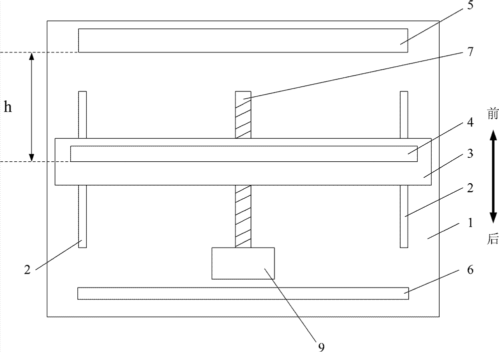
A kind of 3D display that the utility model embodiment provides, as shown in Figure 6, be the rearmounted type 3D of grating display, comprising:
Objective table 1, guide rail 2, lift-launch grating platform 3, grating 4, display panel 5, backlight 6, gearing are screwed leading screw 7, drive unit 9, distance sensing device and control device (not marking among the figure).Certainly, above-mentioned gearing also can be driving belt or drive motor.
Wherein, display panel 5 and backlight 6 are fixedly installed on the objective table 1; Guide rail 2 is separately fixed at the both sides of objective table 1, and all vertical with the plane of display panel 5; Carry grating platform 3 and be arranged in (context is shown in the figure arrow) after the display panel 5, the bottom of carrying grating platform 3 is mutually meshing with guide rail 2, and grating 4 is fixed on the lift-launch grating platform 3.
Leading screw 7 is arranged on objective table 1 and the centre position of carrying grating platform 3, and the major axis of leading screw 7 is vertical with the plane of display panel 5.As shown in Figure 7, the bottom of carrying grating platform 3 is being provided with sawtooth 31 with leading screw 7 contacted positions, and the screw thread of leading screw 7 is mutually meshing with the sawtooth 31 that carries grating platform 3 bottoms; Like this, rotational lead screw 7 just can make and carry grating platform 3 along guide rail 2 slips.
Drive unit 9 is connected an end of leading screw 7, opens drive unit 9 and just can drive leading screw 7 rotations, slides on guide rail 2 thereby drive lift-launch grating platform 3.
Distance sensing device is fixed on the 3D display, and control device is installed in the inside of 3D display, and distance sensing device connects control device through data line, and control device connects drive unit 9 through data line.
After opening distance sensing device; Distance sensing device can be responded to user's position automatically; And send user position information to control device through data line; Control device calculates according to the customer position information that receives, and slides on guide rail 2 thereby then come accessory drive 9 to drive leading screw 7 rotation drive lift-launch grating platforms 3 according to result of calculation.So just can under the user does not carry out the situation of any operation, automatically regulate the distance h of grating 4, thereby reach the purpose of regulating S to display panel 5.
The user's that distance sensing device can also detect automatically change in location; When user's position changes; Distance sensing device sends up-to-date customer position information to control device, through control device drive device drives leading screw 7 is rotated, thereby readjusts the position of grating.Like this, no matter how the user moves, and the 3D display can both be regulated according to user's position automatically, makes the user be in best viewing distance always, thereby makes the user on different distances, can both see desirable 3D effect.
Above-mentioned drive unit can be an electro-motor, and distance sensing device can be infrared ray or camera.
Present embodiment can also comprise the apparatus for adjusting position described in the embodiment two, so that when self-checking device goes wrong, also can regulate the viewing ratio of display.
The embodiment of the utility model provides a kind of 3D display, and the viewing ratio that can automatically regulate display according to the variation of user's position makes the user watch desirable 3D display effect in different distance.
Embodiment four
A kind of 3D display that the utility model embodiment provides, as shown in Figure 8, be grating prefix type 3D display, comprising:
Objective table 1, guide rail 2, lift-launch grating platform 3, grating 4, display panel 5, backlight 6.
Wherein, display panel 5 is fixedly installed on the objective table 1, and carries grating platform 3 and be arranged in (context is shown in Fig. 8 arrow) before the display panel 5, and remainder and embodiment one are identical, specifically can repeat no more with reference to embodiment one.
The embodiment of the utility model provides a kind of 3D display, can make the user watch desirable 3D display effect in different distance through regulating the viewing ratio of display.
Embodiment five
A kind of 3D display that the utility model embodiment provides, as shown in Figure 9, be grating prefix type 3D display, comprising:
Objective table 1, guide rail 2, lift-launch grating platform 3, grating 4, display panel 5, backlight 6, gearing are screwed leading screw 7, apparatus for adjusting position 8.Simultaneously, above-mentioned gearing also can be driving belt or drive motor.
Wherein, display panel 5 is fixedly installed on the objective table 1, and carries grating platform 3 and be arranged in (context is shown in Fig. 9 arrow) before the display panel 5, and remainder and embodiment two are identical, specifically can repeat no more with reference to embodiment two.
The embodiment of the utility model provides a kind of 3D display, can regulate the viewing ratio of display easily and accurately, makes the user watch desirable 3D display effect in different distance.
Embodiment six
A kind of 3D display that the utility model embodiment provides; Shown in figure 10; Be grating prefix type 3D display; Comprise: objective table 1, guide rail 2, lift-launch grating platform 3, grating 4, display panel 5, backlight 6, gearing are screwed leading screw 7, drive unit 9, distance sensing device and control device (not shown).Certainly, above-mentioned gearing also can be driving belt or drive motor.
Wherein, display panel 5 is fixedly installed on the objective table 1, and carries grating platform 3 and be arranged in (context is shown in Fig. 9 arrow) before the display panel 5, and remainder is identical with embodiment three, specifically can repeat no more with reference to embodiment three.
Above-mentioned drive unit can be an electro-motor, and distance sensing device can be infrared ray or camera.
Present embodiment can also comprise the apparatus for adjusting position described in the embodiment five, so that when self-checking device goes wrong, also can regulate the viewing ratio of display.
The embodiment of the utility model provides a kind of 3D display, and the viewing ratio that can automatically regulate display according to the variation of user's position makes the user watch desirable 3D display effect in different distance.
The above; Be merely the embodiment of the utility model; But the protection domain of the utility model is not limited thereto; Any technician who is familiar with the present technique field can expect changing or replacement in the technical scope that the utility model discloses easily, all should be encompassed within the protection domain of the utility model.Therefore, the protection domain of the utility model should be as the criterion with the protection domain of said claim.