CN202494772U - Magnetoresistive sensor for measuring magnetic field - Google Patents
Magnetoresistive sensor for measuring magnetic field Download PDFInfo
- Publication number
- CN202494772U CN202494772U CN 201220053923 CN201220053923U CN202494772U CN 202494772 U CN202494772 U CN 202494772U CN 201220053923 CN201220053923 CN 201220053923 CN 201220053923 U CN201220053923 U CN 201220053923U CN 202494772 U CN202494772 U CN 202494772U
- Authority
- CN
- China
- Prior art keywords
- sensor
- magnetoresistive
- arm
- magnetic field
- magnetoresistance
- Prior art date
- Legal status (The legal status is an assumption and is not a legal conclusion. Google has not performed a legal analysis and makes no representation as to the accuracy of the status listed.)
- Expired - Lifetime
Links
Images


Landscapes
- Measuring Magnetic Variables (AREA)
- Hall/Mr Elements (AREA)
Abstract
本实用新型设计了一种用于测量磁场的磁电阻传感器。本实用新型提供了磁电阻传感元件的灵敏度的计算,该灵敏度与形状各向异性能及外场相关。磁电阻元件的长轴与敏感方向平行,同时具有一个垂直敏感方向的外场分量Hcross可以进一步饱和磁电阻元件的磁矩。单片永磁体的作用是产生具有角度的Hcross场同时抵消沿易磁化轴方向的非理想场。高灵敏度磁电阻元件可以广泛应用在电气领域。本实用新型将会对其构成的六种电桥形式进行阐述。
The utility model designs a magnetoresistance sensor for measuring magnetic fields. The utility model provides the calculation of the sensitivity of the magnetoresistance sensing element, and the sensitivity is related to the shape anisotropy and the external field. The long axis of the magnetoresistive element is parallel to the sensitive direction, and at the same time, there is an external field component H cross perpendicular to the sensitive direction, which can further saturate the magnetic moment of the magnetoresistive element. The role of the monolithic permanent magnet is to generate an angled H cross field while canceling the non-ideal field along the easy axis. High-sensitivity magnetoresistive elements can be widely used in the electrical field. The utility model will set forth the six forms of electric bridges that it constitutes.
Description
技术领域 technical field
本发明涉及了一种磁电阻传感器,尤其为一种用于测量磁场的磁电阻传感器。 The invention relates to a magnetoresistance sensor, in particular to a magnetoresistance sensor for measuring a magnetic field.
背景技术 Background technique
磁性传感器广泛用于现代系统中以测量或感应磁场强度、电流、位置、运动、方向等物理参数。在现有技术中,有许多不同类型的传感器用于测量磁场和其他参数。但是,他们都受到了现有技术中的各种众所周知的限制,例如,尺寸过大,灵敏度低,动态范围窄,成本高,可靠性低以及其他因素。因此,持续地改进磁传感器,特别是改进易与半导体器件或集成电路整合的传感器及其制造方法是有必要的。 Magnetic sensors are widely used in modern systems to measure or sense physical parameters such as magnetic field strength, current, position, motion, orientation, etc. In the prior art, there are many different types of sensors used to measure magnetic fields and other parameters. However, they all suffer from various well-known limitations in the prior art, such as excessive size, low sensitivity, narrow dynamic range, high cost, low reliability, and other factors. Therefore, it is necessary to continuously improve magnetic sensors, especially sensors that are easy to integrate with semiconductor devices or integrated circuits and their manufacturing methods.
隧道结磁电阻传感器具有高灵敏度,尺寸小,成本低以及功耗低等优点。尽管MTJ传感器与半导体标准制造工艺相兼容,但是高灵敏度的MTJ传感器并没有实现低成本大规模生产。特别是传感器的成品率取决于MTJ元件磁阻输出的偏移值,构成电桥的MTJ的磁阻很难达到高的匹配度,同时正交磁场传感器在同一半导体基片上集成的制造工艺非常复杂。 Tunnel junction magnetoresistive sensors have the advantages of high sensitivity, small size, low cost and low power consumption. Although MTJ sensors are compatible with semiconductor standard fabrication processes, high-sensitivity MTJ sensors have not been mass-produced at low cost. In particular, the yield of the sensor depends on the offset value of the reluctance output of the MTJ element. The reluctance of the MTJ forming the bridge is difficult to achieve a high degree of matching. At the same time, the manufacturing process of the orthogonal magnetic field sensor integrated on the same semiconductor substrate is very complicated. .
可用于传感器的磁电阻元件的响应是由传感材料构成的多层膜的磁化方向的函数。为了获得磁感应通常需要一个外场对磁矩进行偏置使其工作在一个稳定灵敏的工作点上。这种偏置方式通常是采用外加线圈或者永磁体,这些设计从功耗、成本和大规模制造的角度来看是不可取的。 The response of the magnetoresistive element that can be used in the sensor is a function of the magnetization direction of the multilayer film composed of the sensing material. In order to obtain magnetic induction, an external field is usually required to bias the magnetic moment to make it work at a stable and sensitive operating point. This biasing method usually uses an external coil or permanent magnet, and these designs are not advisable from the perspective of power consumption, cost and large-scale manufacturing.
发明内容 Contents of the invention
针对上述问题,本发明提供一种用于测量磁场的磁电阻传感器,能够实现大规模生产,测量磁场的灵敏度更高,同时具备功耗低、尺寸小的特点。 In view of the above problems, the present invention provides a magnetoresistive sensor for measuring magnetic fields, which can realize mass production, has higher sensitivity for measuring magnetic fields, and has the characteristics of low power consumption and small size.
本发明公开了一种用于测量磁场的磁电阻传感器,它包括: The invention discloses a magnetoresistance sensor for measuring a magnetic field, which comprises:
基片,所述基片具有一“X-Y”表面,所述磁电阻传感器的敏感轴平行于Y轴,其中X轴垂直于Y轴; a substrate, the substrate has an "X-Y" surface, the sensitive axis of the magnetoresistive sensor is parallel to the Y axis, wherein the X axis is perpendicular to the Y axis;
至少一个感应臂,所述感应臂由磁电阻元件构成,所述磁电阻元件设置在基片的“X-Y”表面上,所述磁电阻元件沿Y轴方向的长度大于其沿X轴方向的长度; At least one sensing arm, the sensing arm is composed of a magneto-resistive element, the magneto-resistive element is arranged on the "X-Y" surface of the substrate, and the length of the magneto-resistive element along the Y-axis direction is greater than its length along the X-axis direction ;
多个设置在所述磁电阻传感器的基片上的条形永磁体,两两相邻的条形永磁体之间形成间隙磁场,该间隙磁场具有沿X轴和Y轴的分量; A plurality of bar-shaped permanent magnets arranged on the substrate of the magnetoresistive sensor, a gap magnetic field is formed between two adjacent bar-shaped permanent magnets, and the gap magnetic field has components along the X-axis and the Y-axis;
焊盘,所述焊盘设置在感应臂的末端可通过其将感应臂相电连。 The welding pad is arranged at the end of the sensing arm and can be used to electrically connect the sensing arm.
优选地,至少一个所述磁电阻元件被所述的间隙磁场在X轴方向饱和。 Preferably, at least one of the magneto-resistive elements is saturated in the X-axis direction by the gap magnetic field.
优选地,所述磁电阻传感器的磁电阻阻值随外场变化的响应曲线在所述磁电阻传感器的工作区间内具有高线性度、高斜率值、低磁滞。 Preferably, the response curve of the magnetoresistance resistance of the magnetoresistance sensor changing with the external field has high linearity, high slope value and low hysteresis within the working range of the magnetoresistance sensor.
优选地,对条形永磁体充磁以调节该条形永磁体的磁化强度和方向以调节所述磁电阻传感器的输出性能。 Preferably, the bar-shaped permanent magnet is magnetized to adjust the magnetization and direction of the bar-shaped permanent magnet to adjust the output performance of the magnetoresistive sensor.
优选地,所述磁电阻元件为MTJ元件或GMR元件。 Preferably, the magnetoresistive element is an MTJ element or a GMR element.
优选地,该磁电阻传感器为桥式磁场传感器。 Preferably, the magnetoresistive sensor is a bridge magnetic field sensor.
优选地,所述桥式磁场传感器为推挽全桥磁场传感器。 Preferably, the bridge-type magnetic field sensor is a push-pull full-bridge magnetic field sensor.
优选地,所述推挽全桥磁场传感器包括四个感应臂,在所述磁电阻传感器的工作区间内其中两个感应臂的磁电阻阻值随外场变化的响应曲线相对另外两个感应臂的磁电阻阻值随外场变化的响应曲线在相同的外场作用下具有相反的变化趋势。 Preferably, the push-pull full-bridge magnetic field sensor includes four sensing arms, and in the working range of the magnetoresistive sensor, the response curves of the magnetoresistance resistance values of two sensing arms changing with the external field are compared with those of the other two sensing arms. The response curve of the magnetoresistance value changing with the external field has the opposite trend under the same external field.
优选地,所述推挽全桥磁场传感器包括两个传感器芯片,每个传感器芯片包括具有“X-Y”表面的基片和设置在基片的表面上的两个感应臂,其中一个传感器芯片为相对另一个传感器芯片旋转180度排布,两个传感器芯片由同一晶圆切割制成。 Preferably, the push-pull full-bridge magnetic field sensor includes two sensor chips, each sensor chip includes a substrate with an "X-Y" surface and two sensing arms arranged on the surface of the substrate, one of the sensor chips is opposite The other sensor chip is rotated by 180 degrees, and the two sensor chips are cut from the same wafer.
优选地,感应臂之间可通过引线连接焊盘实现电连。 Preferably, the sensing arms can be electrically connected to the pads through wires.
优选地,所述桥式磁场传感器为参考全桥磁场传感器,该参考全桥磁场传感器包括感应臂和参考臂,每个参考臂由磁电阻元件构成。 Preferably, the bridge-type magnetic field sensor is a reference full-bridge magnetic field sensor, the reference full-bridge magnetic field sensor includes a sensing arm and a reference arm, and each reference arm is composed of a magnetoresistive element.
优选地,所述的参考全桥磁场传感器包括两个感应臂和两个参考臂,在所述磁电阻传感器的工作区间内感应臂的磁电阻阻值随外场变化的响应曲线的斜率绝对值远大于参考臂的磁电阻阻值随外场变化的响应曲线的斜率绝对值。 Preferably, the reference full-bridge magnetic field sensor includes two sensing arms and two reference arms, and in the working range of the magnetoresistive sensor, the absolute value of the slope of the response curve of the magnetoresistance resistance of the sensing arm changing with the external field is much larger The absolute value of the slope of the response curve of the magnetoresistance value of the reference arm changing with the external field.
优选地,所述的参考全桥磁场传感器包括一个传感器芯片,该传感器芯片上包括具有“X-Y”表面的基片和设置在基片的表面上的构成感应臂的磁电阻元件和构成参考臂的磁电阻元件。 Preferably, the reference full-bridge magnetic field sensor includes a sensor chip, which includes a substrate with an "X-Y" surface and a magnetoresistive element that constitutes the sensing arm and a magneto-resistive element that constitutes the reference arm that are arranged on the surface of the substrate. magnetoresistive element.
优选地,构成所述参考臂的磁电阻元件沿X轴方向的长度大于其沿Y轴方向的长度,在X轴方向的长度大于构成所述感应臂的磁电阻元件在X轴方向的长度。 Preferably, the length of the magneto-resistive element constituting the reference arm along the X-axis direction is greater than its length along the Y-axis direction, and the length in the X-axis direction is greater than the length of the magneto-resistive element constituting the sensing arm in the X-axis direction.
优选地,所述构成参考臂的磁电阻元件的表面覆盖有一层高磁导率的铁磁屏蔽层。 Preferably, the surface of the magnetoresistive element constituting the reference arm is covered with a ferromagnetic shielding layer with high magnetic permeability.
优选地,设置在参考臂附近的条形永磁体在其X轴方向的分量大于设置在传感臂附近的条形永磁体在其X轴方向的分量。 Preferably, the component of the bar-shaped permanent magnet arranged near the reference arm in its X-axis direction is greater than the component of the bar-shaped permanent magnet arranged near the sensing arm in its X-axis direction.
优选地,构成参考臂或感应臂的磁电阻元件上设置有一层或多层永磁偏置层。 Preferably, one or more permanent magnetic bias layers are arranged on the magnetoresistive element constituting the reference arm or the sensing arm.
优选地,构成参考臂的磁电阻元件上设置有一层或多层交换偏置层。 Preferably, one or more exchange bias layers are arranged on the magnetoresistive element constituting the reference arm.
优选地,所述桥式磁场传感器为推挽半桥磁场传感器,该推挽半桥磁场传感器由两个感应臂构成。 Preferably, the bridge-type magnetic field sensor is a push-pull half-bridge magnetic field sensor, and the push-pull half-bridge magnetic field sensor is composed of two sensing arms.
优选地,所述推挽半桥磁场传感器包括两个感应臂,在所述磁电阻传感器的工作区间内其中一个感应臂的磁电阻阻值随外场变化的响应曲线相对另一个感应臂的磁电阻阻值随外场变化的的响应曲线在相同的外场作用下具有相反的变化趋势。 Preferably, the push-pull half-bridge magnetic field sensor includes two sensing arms, and in the working range of the magnetoresistive sensor, the magnetoresistance resistance of one sensing arm varies with the response curve of the external field relative to the magnetoresistance of the other sensing arm The response curve of the resistance changing with the external field has the opposite trend under the same external field.
优选地,所述的推挽半桥磁场传感器包括两个传感器芯片,每个传感器芯片包括具有“X-Y”表面的基片和设置在基片的表面上的感应臂,其中一个传感器芯片为相对另一个传感器芯片旋转180度排布,两个传感器芯片由同一晶圆切割制成。 Preferably, the push-pull half-bridge magnetic field sensor includes two sensor chips, each sensor chip includes a substrate with an "X-Y" surface and sensing arms arranged on the surface of the substrate, wherein one sensor chip is opposite to the other. One sensor chip is rotated 180 degrees and two sensor chips are cut from the same wafer.
优选地,所述的推挽半桥磁场传感器的感应臂之间可通过引线连接焊盘实现电连。 Preferably, the sensing arms of the push-pull half-bridge magnetic field sensor can be electrically connected to pads through wires.
优选地,该磁电阻传感器为参考半桥磁场传感器,该参考半桥磁场传感器包括感应臂和参考臂,每个参考臂由磁电阻元件构成。 Preferably, the magnetoresistive sensor is a reference half-bridge magnetic field sensor, the reference half-bridge magnetic field sensor includes a sensing arm and a reference arm, and each reference arm is composed of a magnetoresistive element.
优选地,所述的参考半桥磁场传感器包括一个感应臂和一个参考臂,在所述磁电阻传感器的工作区间内感应臂的磁电阻阻值随外场变化的响应曲线的斜率绝对值远大于参考臂的磁电阻阻值随外场变化的响应曲线的斜率绝对值。 Preferably, the reference half-bridge magnetic field sensor includes a sensing arm and a reference arm, and in the working range of the magnetoresistive sensor, the absolute value of the slope of the response curve of the magnetoresistance resistance of the sensing arm changing with the external field is much greater than that of the reference The absolute value of the slope of the response curve of the magnetoresistance value of the arm changing with the external field.
优选地,所述的参考半桥磁场传感器包括一个传感器芯片,该传感器芯片上包括“X-Y”表面的基片和设置在基片的表面上的构成感应臂的磁电阻元件和构成参考臂的磁电阻元件。 Preferably, the reference half-bridge magnetic field sensor includes a sensor chip, the sensor chip includes a substrate with an "X-Y" surface and a magnetoresistive element that constitutes the sensing arm and a magnetoresistive element that constitutes the reference arm that are arranged on the surface of the substrate. resistive element.
优选地,构成所述参考臂的磁电阻元件沿X轴方向的长度大于其沿Y轴方向的长度,在X轴方向的长度大于构成所述感应臂的磁电阻元件在X轴方向的长度。 Preferably, the length of the magneto-resistive element constituting the reference arm along the X-axis direction is greater than its length along the Y-axis direction, and the length in the X-axis direction is greater than the length of the magneto-resistive element constituting the sensing arm in the X-axis direction.
优选地,所述构成参考臂的磁电阻元件的表面覆盖有一层高磁导率的铁磁屏蔽层。 Preferably, the surface of the magnetoresistive element constituting the reference arm is covered with a ferromagnetic shielding layer with high magnetic permeability.
优选地,设置在参考臂附近的条形永磁体在其X轴方向的分量大于设置在传感臂附近的条形永磁体在其X轴方向的分量。 Preferably, the component of the bar-shaped permanent magnet arranged near the reference arm in its X-axis direction is greater than the component of the bar-shaped permanent magnet arranged near the sensing arm in its X-axis direction.
优选地,构成参考臂或感应臂的磁电阻元件上设置有一层或多层永磁偏置层。 Preferably, one or more permanent magnetic bias layers are arranged on the magnetoresistive element constituting the reference arm or the sensing arm.
优选地,构成参考臂的磁电阻元件上设置有一层或多层交换偏置层。 Preferably, one or more exchange bias layers are arranged on the magnetoresistive element constituting the reference arm.
优选地,该磁电阻传感器为由两个独立的电流驱动源和两个感应臂全桥连接构成的半推挽全桥磁场传感器。 Preferably, the magnetoresistive sensor is a half-push-pull full-bridge magnetic field sensor composed of two independent current drive sources and two full-bridge connections of sensing arms.
优选地,所述半推挽全桥磁场传感器中的一个感应臂的磁电阻阻值随外场变化的响应曲线相对另一个感应臂的磁电阻阻值随外场变化的响应曲线在相同的外场具有相反的变化趋势。 Preferably, in the half-push-pull full-bridge magnetic field sensor, the response curve of the magnetoresistance resistance of one sensing arm varying with the external field is opposite to the response curve of the magnetoresistance resistance of the other sensing arm varying with the external field in the same external field. trend of change.
优选地,所述半推挽全桥磁场传感器包括两个传感器芯片,每个传感器芯片包括具有“X-Y”表面的基片和设置在基片的表面上的感应臂,其中一个传感器芯片为相对另一个传感器芯片旋转180度排布,两个传感器芯片由同一晶圆切割制成。 Preferably, the half-push-pull full-bridge magnetic field sensor includes two sensor chips, each sensor chip includes a substrate with an "X-Y" surface and sensing arms arranged on the surface of the substrate, wherein one sensor chip is opposite to the other. One sensor chip is rotated 180 degrees and two sensor chips are cut from the same wafer.
优选地,所述半推挽全桥磁场传感器的感应臂之间可通过引线连接焊盘实现电连。 Preferably, the sensing arms of the half-push-pull full-bridge magnetic field sensor can be electrically connected to pads through wires.
优选地,该磁电阻传感器为由两个独立的电流驱动源、一个感应臂和一个参考臂全桥连接构成的半参考全桥磁场传感器。 Preferably, the magnetoresistive sensor is a half-reference full-bridge magnetic field sensor composed of two independent current drive sources, a sensing arm and a reference arm full-bridge connection.
优选地,所述感应臂的磁电阻阻值随外场变化的响应曲线的斜率绝对值远大于参考臂的磁电阻阻值随外场变化的响应曲线的斜率绝对值。 Preferably, the absolute value of the slope of the response curve of the magnetoresistance resistance of the sensing arm varying with the external field is much larger than the absolute value of the slope of the response curve of the magnetoresistance resistance of the reference arm varying with the external field.
优选地,所述半参考全桥磁场传感器包括一个传感器芯片,该传感器芯片包括具有“X-Y”表面的基片和设置在基片的表面上的构成感应臂的磁电阻元件和构成参考臂的磁电阻元件。 Preferably, the half-reference full-bridge magnetic field sensor includes a sensor chip, the sensor chip includes a substrate with an "X-Y" surface, and a magnetoresistive element constituting the sensing arm and a magnetoresistive element constituting the reference arm disposed on the surface of the substrate. resistive element.
优选地,构成所述参考臂的磁电阻元件沿X轴方向的长度大于其沿Y轴方向的长度,在X轴方向的长度大于构成所述感应臂的磁电阻元件在X轴方向的长度。 Preferably, the length of the magneto-resistive element constituting the reference arm along the X-axis direction is greater than its length along the Y-axis direction, and the length in the X-axis direction is greater than the length of the magneto-resistive element constituting the sensing arm in the X-axis direction.
优选地,所述构成参考臂的磁电阻元件的表面覆盖有一层高磁导率的铁磁屏蔽层。 Preferably, the surface of the magnetoresistive element constituting the reference arm is covered with a ferromagnetic shielding layer with high magnetic permeability.
优选地,设置在参考臂附近的条形永磁体在其X轴方向的分量大于设置在传感臂附近的条形永磁体在其X轴方向的分量。 Preferably, the component of the bar-shaped permanent magnet arranged near the reference arm in its X-axis direction is greater than the component of the bar-shaped permanent magnet arranged near the sensing arm in its X-axis direction.
优选地,构成参考臂或感应臂的磁电阻元件上设置有一层或多层用磁偏置层。 Preferably, one or more magnetic bias layers are provided on the magnetoresistive element constituting the reference arm or the sensing arm.
优选地,构成参考臂的磁电阻元件上设置有一层或多层交换偏置层。 Preferably, one or more exchange bias layers are arranged on the magnetoresistive element constituting the reference arm.
本发明提供了一种标准半导体制造工艺、用于规模生产的线性桥式磁电阻传感器。该传感器采用高灵敏度的磁电阻传感元件例如隧道结磁电阻(MTJ)或者巨磁电阻(GMR)多层膜。设置单片永磁体是用来产生散场以提供偏置场以抵消传感元件的非理想磁行为。该永磁体产生的偏置场可以平衡内部的沿敏感方向的形状和材料的各向异性能,同时交叉轴磁偏置场可以优化传感器的灵敏度。因此高灵敏度磁场敏感元件可通过连接成电桥形式进一步加强其低偏移,高线性度,好的温度稳定性以拓宽其适用的领域。 The invention provides a standard semiconductor manufacturing process for a linear bridge magnetoresistance sensor used in mass production. The sensor uses highly sensitive magnetoresistive sensing elements such as tunnel junction magnetoresistance (MTJ) or giant magnetoresistance (GMR) multilayer films. A monolithic permanent magnet is provided to generate a fringe field to provide a bias field to counteract the non-ideal magnetic behavior of the sensing element. The bias field generated by the permanent magnet can balance the internal shape along the sensitive direction and the anisotropy of the material, while the cross-axis magnetic bias field can optimize the sensitivity of the sensor. Therefore, the high-sensitivity magnetic field sensitive element can further enhance its low offset, high linearity, and good temperature stability by connecting it in the form of a bridge to broaden its applicable field.
附图说明 Description of drawings
图1是一个隧道结磁电阻(MTJ)的横截面示意图,在MTJ元件的顶电极层和底电极层之间连接有欧姆表显示其阻值变化。 Figure 1 is a schematic cross-sectional view of a tunnel junction magnetoresistance (MTJ). An ohmmeter is connected between the top electrode layer and the bottom electrode layer of the MTJ element to show its resistance change.
图2是自旋阀元件参考层沿难轴方向磁化的磁电阻响应示意图。 Fig. 2 is a schematic diagram of the magnetoresistance response of the reference layer of the spin valve element magnetized along the hard axis direction.
图3是MTJ元件的响应曲线图, Figure 3 is the response curve of the MTJ element,
图4是旋转180°的后的MTJ元件在同一外场作用下(flipped die)的响应曲线图。 Figure 4 is the response curve of the MTJ element rotated 180° under the same external field (flipped die).
图5是将多个MTJ元件连接为一个磁电阻元件的示意图。 Fig. 5 is a schematic diagram of connecting multiple MTJ elements into one magnetoresistive element.
图6是推挽全桥传感器的电路示意图。 FIG. 6 is a schematic circuit diagram of a push-pull full-bridge sensor.
图7是参考全桥传感器的电路示意图。 FIG. 7 is a schematic circuit diagram of a reference full bridge sensor.
图8是推挽半桥传感器的电路示意图。 FIG. 8 is a schematic circuit diagram of a push-pull half-bridge sensor.
图9是参考半桥传感器的电路示意图。 FIG. 9 is a schematic circuit diagram of a reference half-bridge sensor.
图10是半推挽全桥磁场传感器的电路示意图。 Fig. 10 is a schematic circuit diagram of a half-push-pull full-bridge magnetic field sensor.
图11是半参考全桥传感器的电路示意图。 Figure 11 is a schematic circuit diagram of a half-referenced full-bridge sensor.
图12是桥式电路随外场变化的输出电压模拟示意图,该桥式电路由四个高灵敏度的MTJ元件的桥臂翻转排列构成。 Fig. 12 is a schematic diagram of the simulation of the output voltage of the bridge circuit changing with the external field. The bridge circuit is composed of four high-sensitivity MTJ elements in which the bridge arms are flipped and arranged.
图13标示了集成永磁体摆放的位置。永磁体相对于MTJ传感元件的长轴以及敏感轴平行。 Figure 13 indicates the placement of the integrated permanent magnets. The permanent magnet is parallel to the long axis of the MTJ sensing element and the sensitive axis.
图14是图16所示的永磁体和MTJ元件的截面图以及一对永磁体的磁感线分布。 FIG. 14 is a cross-sectional view of the permanent magnet and MTJ element shown in FIG. 16 and the distribution of magnetic flux lines of a pair of permanent magnets.
图15是通过设置MTJ元件周围的场强和方向的角度来控制其响应曲线的偏移和饱和场。 Figure 15 shows the offset and saturation field of the response curve controlled by setting the angle of the field strength and direction around the MTJ element.
图16是传感元件所处的一对片式永磁体中间的磁场分布,磁场强度是磁体宽度和磁体间距的函数。 Fig. 16 is the magnetic field distribution between a pair of piece permanent magnets where the sensing element is located, and the magnetic field strength is a function of the width of the magnet and the distance between the magnets.
图17是图16中的磁电阻元件周围的磁场分量示意图。图18是灵敏度关于Hcross/Hk的函数图。 FIG. 17 is a schematic diagram of magnetic field components around the magnetoresistive element in FIG. 16 . Figure 18 is a graph of sensitivity as a function of Hcross / Hk .
图19是两个芯片翻转排列的传感器设计布局图,每一块芯片都有两个传感臂,两块芯片构成一全桥。相同的两块芯片沿基片标准轴旋转180°排列。 Figure 19 is a layout diagram of a sensor design in which two chips are flipped and arranged. Each chip has two sensing arms, and the two chips form a full bridge. The same two chips are arranged rotated 180° along the standard axis of the substrate.
图20是一种规范的参考桥式传感器芯片布局图,该设计利用倾斜的永磁体设置传感臂的偏置场,竖直排列的永磁体设置参考臂的偏置场以优化电桥的输出,同时可以选择性地设置屏蔽层。 Figure 20 is a canonical layout of a reference bridge sensor chip. This design uses inclined permanent magnets to set the bias field of the sensing arm, and vertically arranged permanent magnets set the bias field of the reference arm to optimize the output of the bridge. , and can optionally set the shielding layer.
具体实施方式 Detailed ways
图1是隧道结磁电阻(Magnetic Tunnel Junctions, MTJ)元件的结构和电子测量原理图。MTJ元件1由钉扎层2、隧道势垒层5、铁磁层(敏感层)6构成。钉扎层2由铁磁层(被钉扎层)4和反铁磁层3构成,铁磁层4和反铁磁层3之间的交换耦合作用决定了铁磁层4的磁化方向;隧道势垒层5通常由MgO或Al2O3构成,位于铁磁层4的上部。铁磁层6位于隧道势垒层5的上部。箭头8和箭头7分别代表被钉扎层4和敏感层6的磁化方向。被钉扎层4的磁矩8在一定大小的磁场作用下是相对固定的,敏感层6的磁矩7相对于被钉扎层4的磁矩8的是相对自由且可旋转的。3、4、5、6的典型厚度为0.1 nm到100 nm之间。
Figure 1 is a schematic diagram of the structure and electronic measurement of the tunnel junction magnetoresistance (Magnetic Tunnel Junctions, MTJ) element. The
底电极层16和顶电极层17直接与相关的反铁磁层3和敏感层6电接触。电极层通常采用非磁性导电材料,能够携带电流输入欧姆计18。欧姆计18适用于已知的穿过整个隧道结的电流,并对电流(或电压)进行测量。通常情况下,隧道势垒层5提供了器件的大多数电阻,约为1000欧姆,而所有导体的阻值约为10欧姆。底电极层16位于绝缘基片9上方,绝缘基片9要比底电极层16要宽其位于其他材料构成的底基片10的上方。底基片的材料通常是硅、石英、耐热玻璃、GaAs、AlTiC或者是能够于晶圆集成的任何其他材料。硅由于其易于加工为集成电路(尽管磁性传感器不总是需要这种电路)成为最好的选择。
The bottom electrode layer 16 and the top electrode layer 17 are in direct electrical contact with the associated
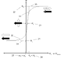
适合线性磁场测量的GMR或MTJ元件的输出图如图2所示。响应曲线20在低阻态21和高阻态22饱和,RL和RH分别代表低阻态和高阻态的阻值。响应曲线20在饱和场之间的区域是随外场Hsense线性变化的。外场Hsense平行于传感元件的敏感轴。被钉扎层4的磁矩8与敏感轴反平行意味着其指向-H的方向。当自由层6的磁矩7与被钉扎层4的磁矩8反平行时,磁电阻元件的响应曲线20为最大值,当两者平行时,为最小值。磁电阻响应曲线20的中间值随自由层6和被钉扎层4之间的角度的变化而变化。响应曲线20不是沿H=0的点对称的。饱和场25、26沿着HO点23典型的偏移场因此RL值对应的饱和场更接近H=0的点。HO值通常被称为“橘子皮效应(Orange Peel)”或“奈尔耦合(Neel Coupling)”,其典型值为1到40 Oe。其与磁电阻元件中铁磁性薄膜的结构和平整度有关,依赖于材料和制造工艺。
The output plot of a GMR or MTJ element suitable for linear magnetic field measurements is shown in Figure 2. The
如图2所示的响应曲线在饱和场25和26之间的区域的工作状态可以近似为方程: The operating state of the response curve shown in Figure 2 in the region between the saturation fields 25 and 26 can be approximated by the equation:

其中,HS是饱和场。HS被定量地定义为线性区域的切线与正负饱和曲线的切线的交点对应的值,该值是在响应曲线相对于HO点的不对称性消除的情况下所取的。 where HS is the saturation field. HS was quantitatively defined as the value corresponding to the intersection of the tangent of the linear region and the tangent of the positive and negative saturation curves, taken with the asymmetry of the response curve with respect to the HO point eliminated.
图2所示的是在理想情况下的响应曲线20。在理想状态下,磁电阻R随外场Hsense的变化是完美的线性关系,同时没有磁滞(在实际情况下,磁电阻的响应曲线随外场变化具有滞后的现象,我们称之为磁滞。磁电阻的响应曲线为一个回路,通常作为应用的磁电阻材料的磁滞很小,在实际使用中可以看做一个完美的线性曲线)。在现实应用的传感器领域,由于磁传感设计的制约以及材料的缺陷,这条曲线20会更弯曲。本发明涉及了传感器的设计、结构以及能够生产实施的工序,该传感器具有卓越的工作感应,在工作区域内同时具有高线性度、低磁滞、高灵敏度的特点(即磁电阻响应曲线斜率大)。
Figure 2 shows the
R-Hsense曲线30具有低阻态21的阻值RL和高阻态22的阻值RH。其高灵敏度的区域是在零场附近,传感器的工作区间位于零场附近,约为饱和场25和26之间1/3的区域。曲线30在H=0点处的切线为33。 该曲线的斜率和传感器的灵敏度成正比。零场切线33分别和低场切线34以及高场切线35相交于点25(-HS+HO)和点26(HS+HO)。如图3所示,当磁矩7与磁矩8反平行时,曲线30对应高阻态;当磁矩7和磁矩8平行时,曲线30对应低阻态。当7和8垂直时,阻值是位于RL和RH之间的中间值,这是理想的线性磁传感器的“工作点”。如图4所示,另一个磁电阻R与外场Hsense的变化曲线,该磁电阻是沿传感器的法线旋转了180°。在同一外场Hsense的作用下,该磁电阻R的被钉扎层4的和矢量磁矩8是平行于外场Hsense的。在这种情况下,旋转的芯片的R-Hsense的斜率为负值。普通摆放的磁电阻和旋转180°设置的磁电阻可以构造电桥,这被证明比其他可能的方法输出值更大。
The RH sense curve 30 has a resistance value R L in the
由于尺寸小,MTJ元件能够连接成串以增加灵敏度,噪声减少至1/F,同时可以提高其ESD性能,其实施方式见图5。这些磁电阻元件串被用来作为更为复杂的电路结构的磁电阻臂。MTJ元件40在底电极41和顶电极42层中间成三明治结构,内部的电流43垂直通过MTJ元件40水平方向交替流过顶电极层和底电极层。底电极41在绝缘层9的上方,而绝缘层9位于底基片10上。在每个元件串的末端是焊盘,也就是电阻臂和其他元件或欧姆计18连接的地方或者可以通过其和芯片上其他电路的部件连接而没有任何其他的连接方式。在通常情况下电流流动的方向并不对桥臂电阻的有效电阻产生影响。保持参考臂和感应臂的MTJ元件的尺寸相同是有利的,因为这会导致器件的刻蚀偏置不敏感,同时参考臂和感应臂MTJ元件串的电阻值是可以根据MTJ元件个数设置和改变的。
Due to the small size, MTJ elements can be connected in series to increase sensitivity, reduce noise to 1/F, and improve ESD performance at the same time. See Figure 5 for its implementation. These strings of magneto-resistive elements are used as magneto-resistive arms for more complex circuit structures. The
电桥是用来改变磁电阻传感器的信号,使其输出电压便于被放大。这可以改变信号的噪声,取消共模信号,减少温漂或其他的不足。上述的MTJ元件串可以连接构成惠斯通电桥或其他电桥。 The bridge is used to change the signal of the magnetoresistive sensor so that its output voltage can be easily amplified. This can change the noise of the signal, cancel common mode signals, reduce temperature drift or other defects. The above-mentioned MTJ element strings can be connected to form a Wheatstone bridge or other bridges.
图6是推挽全桥传感器电路的示意图。推挽全桥磁场传感器包括四个感应臂,在所述磁电阻传感器的工作区间内其中两个感应臂的磁电阻阻值随外场变化的响应曲线相对另外两个感应臂的磁电阻阻值随外场变化的响应曲线在相同的外场作用下具有相反的变化趋势。 FIG. 6 is a schematic diagram of a push-pull full-bridge sensor circuit. The push-pull full-bridge magnetic field sensor includes four sensing arms. In the working range of the magnetoresistive sensor, the response curves of the magnetoresistance resistance of two sensing arms changing with the external field are relative to the magnetoresistance resistance of the other two sensing arms. The response curves of external field changes have the opposite trend under the same external field.
推挽全桥磁场传感器包括两个传感器芯片,每个传感器芯片包括具有“X-Y”表面的基片和设置在基片的表面上的两个感应臂,其中一个传感器芯片为相对另一个传感器芯片旋转180度排布,两个传感器芯片由同一晶圆切割制成。 The push-pull full-bridge magnetic field sensor includes two sensor chips, each sensor chip includes a substrate with an "X-Y" surface and two sensing arms arranged on the surface of the substrate, one sensor chip is rotated relative to the other sensor chip Arranged at 180 degrees, the two sensor chips are cut from the same wafer.
感应臂之间可通过引线连接焊盘实现电连。 The sensing arms can be electrically connected to the pads through wires.
图7是参考全桥传感器电路的示意图。 7 is a schematic diagram of a reference full bridge sensor circuit.
桥式磁场传感器为参考全桥磁场传感器,该参考全桥磁场传感器包括感应臂和参考臂,每个参考臂由磁电阻元件构成。 The bridge-type magnetic field sensor is a reference full-bridge magnetic field sensor, and the reference full-bridge magnetic field sensor includes a sensing arm and a reference arm, and each reference arm is composed of a magnetoresistive element.
参考全桥磁场传感器包括两个感应臂和两个参考臂,在所述磁电阻传感器的工作区间内感应臂的磁电阻阻值随外场变化的响应曲线的斜率绝对值远大于参考臂的磁电阻阻值随外场变化的响应曲线的斜率绝对值。 The reference full-bridge magnetic field sensor includes two sensing arms and two reference arms. In the working range of the magnetoresistive sensor, the absolute value of the slope of the response curve of the magnetoresistance resistance of the sensing arm changing with the external field is much larger than the magnetoresistance of the reference arm The absolute value of the slope of the response curve of the resistance changing with the external field.
参考全桥磁场传感器包括一个传感器芯片,该传感器芯片上包括具有“X-Y”表面的基片和设置在基片的表面上的构成感应臂的磁电阻元件和构成参考臂的磁电阻元件。 The reference full-bridge magnetic field sensor includes a sensor chip, which includes a substrate with an "X-Y" surface and magnetoresistive elements constituting the sensing arm and magnetoresistive elements constituting the reference arm arranged on the surface of the substrate.
图8是推挽半桥传感器电路的示意图。 8 is a schematic diagram of a push-pull half-bridge sensor circuit.
桥式磁场传感器为推挽半桥磁场传感器,该推挽半桥磁场传感器由两个感应臂构成。 The bridge-type magnetic field sensor is a push-pull half-bridge magnetic field sensor, and the push-pull half-bridge magnetic field sensor is composed of two sensing arms.
推挽半桥磁场传感器包括两个感应臂,在所述磁电阻传感器的工作区间内其中一个感应臂的磁电阻阻值随外场变化的响应曲线相对另一个感应臂的磁电阻阻值随外场变化的的响应曲线在相同的外场作用下具有相反的变化趋势。 The push-pull half-bridge magnetic field sensor includes two sensing arms. In the working range of the magnetoresistive sensor, the magnetoresistance resistance of one sensing arm changes with the response curve of the external field relative to the magnetoresistance resistance of the other sensing arm. The response curves have opposite trends under the same external field.
推挽半桥磁场传感器包括两个传感器芯片,每个传感器芯片包括具有“X-Y”表面的基片和设置在基片的表面上的感应臂,其中一个传感器芯片为相对另一个传感器芯片旋转180度排布,两个传感器芯片由同一晶圆切割制成。 The push-pull half-bridge magnetic field sensor includes two sensor chips, each sensor chip includes a substrate with an "X-Y" surface and a sensing arm arranged on the surface of the substrate, and one sensor chip is rotated 180 degrees relative to the other sensor chip arrangement, two sensor chips are cut from the same wafer.
推挽半桥磁场传感器的感应臂之间可通过引线连接焊盘实现电连。 The sensing arms of the push-pull half-bridge magnetic field sensor can be electrically connected to the pads through wires.
图9是参考半桥传感器电路的示意图。 9 is a schematic diagram of a reference half-bridge sensor circuit.
该磁电阻传感器为参考半桥磁场传感器,该参考半桥磁场传感器包括感应臂和参考臂,参考臂由磁电阻元件构成。 The magnetoresistance sensor is a reference half-bridge magnetic field sensor, and the reference half-bridge magnetic field sensor includes a sensing arm and a reference arm, and the reference arm is composed of a magnetoresistance element.
参考半桥磁场传感器包括一个感应臂和一个参考臂,在所述磁电阻传感器的工作区间内感应臂的磁电阻阻值随外场变化的响应曲线的斜率绝对值远大于参考臂的磁电阻阻值随外场变化的响应曲线的斜率绝对值。 The reference half-bridge magnetic field sensor includes a sensing arm and a reference arm, and the absolute value of the slope of the response curve of the magnetoresistance resistance of the sensing arm varying with the external field within the working range of the magnetoresistance sensor is much greater than the magnetoresistance resistance of the reference arm The absolute value of the slope of the response curve as a function of the external field.
参考半桥磁场传感器包括一个传感器芯片,该传感器芯片上包括“X-Y”表面的基片和设置在基片的表面上的构成感应臂的磁电阻元件和构成参考臂的磁电阻元件。 The reference half-bridge magnetic field sensor includes a sensor chip, which includes a substrate with an "X-Y" surface, magnetoresistive elements constituting the sensing arm and magnetoresistive elements constituting the reference arm arranged on the surface of the substrate.
图10是半推挽全桥磁场传感器电路的示意图。 10 is a schematic diagram of a half-push-pull full-bridge magnetic field sensor circuit.
该磁电阻传感器为由两个独立的电流驱动源和两个感应臂全桥连接构成的半推挽全桥磁场传感器。 The magnetoresistance sensor is a half-push-pull full-bridge magnetic field sensor composed of two independent current drive sources and two full-bridge connections of sensing arms.
半推挽全桥磁场传感器中的一个感应臂的磁电阻阻值随外场变化的响应曲线相对另一个感应臂的磁电阻阻值随外场变化的响应曲线在相同的外场具有相反的变化趋势。 In the half push-pull full-bridge magnetic field sensor, the response curve of the magnetoresistance resistance of one sensing arm changing with the external field has an opposite trend to the response curve of the magnetoresistance resistance of the other sensing arm varying with the external field in the same external field.
半推挽全桥磁场传感器包括两个传感器芯片,每个传感器芯片包括具有“X-Y”表面的基片和设置在基片的表面上的感应臂,其中一个传感器芯片为相对另一个传感器芯片旋转180度排布,两个传感器芯片由同一晶圆切割制成。 The half-push-pull full-bridge magnetic field sensor includes two sensor chips, each sensor chip includes a substrate with an "X-Y" surface and sensing arms arranged on the surface of the substrate, and one sensor chip is rotated 180° relative to the other sensor chip. The two sensor chips are cut from the same wafer.
半推挽全桥磁场传感器的感应臂之间可通过引线连接焊盘实现电连。 The sensing arms of the half-push-pull full-bridge magnetic field sensor can be electrically connected to the pads through wires.
图11是半参考全桥传感器电路的示意图。 11 is a schematic diagram of a half-referenced full-bridge sensor circuit.
由两个独立的电流驱动源、一个感应臂和一个参考臂全桥连接构成了半参考全桥磁场传感器。 A half-reference full-bridge magnetic field sensor is composed of two independent current-driven sources, a sensing arm and a reference arm full-bridge connection.
感应臂的磁电阻阻值随外场变化的响应曲线的斜率绝对值远大于参考臂的磁电阻阻值随外场变化的响应曲线的斜率绝对值。 The absolute value of the slope of the response curve of the magnetoresistance resistance of the sensing arm varying with the external field is much larger than the slope absolute value of the response curve of the magnetoresistance resistance of the reference arm varying with the external field.
半参考全桥磁场传感器包括一个传感器芯片,该传感器芯片包括具有“X-Y”表面的基片和设置在基片的表面上的构成感应臂的磁电阻元件和构成参考臂的磁电阻元件。 The half-reference full-bridge magnetic field sensor includes a sensor chip, which includes a substrate with an "X-Y" surface and a magnetoresistive element constituting a sensing arm and a magnetoresistive element constituting a reference arm arranged on the surface of the substrate.
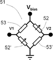
以电桥形式为“推挽全桥磁场传感器”50为例,该电桥含有四个随外场Hsense变化的桥臂,这些桥臂被定义为“感应臂”;正负桥臂的焊盘27、28在任意一个感应臂52的底部。为清晰起见这些焊盘在图中并未标示。感应臂52和52'的响应曲线R-Hsense的斜率为正值,同一外场作用下,感应臂54和54'的响应曲线R-Hsense的斜率为负值。位于52和54上的箭头的方向暗示了各自的R-Hsense曲线的斜率的符号。
Taking the form of the bridge as "push-pull full-bridge magnetic field sensor" 50 as an example, the bridge contains four bridge arms that vary with the H sense of the external field, and these bridge arms are defined as "sensing arms"; the pads of the positive and negative bridge arms 27, 28 are at the bottom of any
从顶端开始顺着圆周呈菱形排列的推挽全桥磁场传感器50的电焊盘为:偏置电压(Vbias, 45);右臂中心焊盘(V2, 48);地线焊盘(GND, 46)以及左臂中心焊盘(V1, 47)。传感器桥臂在基片9、10上制备且具有基片上的电触点,其布局图如上图所述。有很多种方式连接电桥臂和电桥的外接焊盘。典型的连接结构包括:芯片集成连接、绑线键合以及焊球连接。
The electrical pads of the push-pull full-bridge
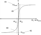
推挽全桥磁场传感器50的V-Hsense输出曲线60如图12所示。由附图3和附图4的RH和RL得到该曲线,首先需要计算输出电压V1-V2随外场Hsense的变化。在这种情况下,感应臂(52、52')以及(54、54')的值分别为RH和RL。电桥电路的阻值为:
The VH sense output curve 60 of the push-pull full-bridge

当左右桥臂具有相同的阻值,电流通过左右两侧电桥之后被平分: When the left and right bridge arms have the same resistance, the current is divided equally after passing through the left and right bridges:

左桥臂中心点的电压V1为: The voltage V1 at the center point of the left bridge arm is:

右桥臂中心点的电压V2为: The voltage V2 at the center point of the right bridge arm is:
, (5) , (5)
桥式传感器的输出被定义为: The output of the bridge sensor is defined as:

因此,输出电压V在正场方向上的最大值如图12所示为+Vpeak, 61。可以看到切线63穿过原点和+Vpeak61相交于Hsense=Hsat的点。因此,桥式电路的输出灵敏度被定义为桥式电路的输出在H=0的点的一阶导数:
Therefore, the maximum value of the output voltage V in the positive field direction is +V peak , 61 as shown in FIG. 12 . It can be seen that the tangent 63 passes through the origin and intersects +
, (7) , (7)
而, and,

其中Hcross是沿着传感器平面垂直于敏感方向为其提供磁偏置场以偏置自由层磁矩7的场。Hk是磁矩7的净有效各向异性能。Hk可以通过独立的方式例如震动样品磁强计(Vibrating Sample Magnetomete, VSM)或超导量子干涉仪(Superconducting Quantum Interference Device, SQUID)进行测量。此时我们替将方程8代入方程7可以得到灵敏度的V-Hsense曲线,如图12所示:
where H cross is the field that provides it with a magnetic bias field to bias the free layer magnetic moment 7 along the sensor plane perpendicular to the sensing direction. H k is the net effective anisotropy energy of magnetic moment 7 . H k can be measured by an independent method such as a vibrating sample magnetometer (Vibrating Sample Magnetomete, VSM) or a superconducting quantum interference device (Superconducting Quantum Interference Device, SQUID). At this point, instead of substituting

前面我们已经详细描述了推挽全桥传感器50的灵敏度的计算。
We have previously described the calculation of the sensitivity of the push-pull full-
接下来将针对相关的六种电桥形式的灵敏度做一个表格进行对比,此处省略完全的推导过程。电桥的结构如图6-11所示。其相对应的灵敏度和峰值电压如表1。 Next, a table will be made for comparison of the sensitivities of the six related bridge forms, and the complete derivation process will be omitted here. The structure of the bridge is shown in Figure 6-11. Its corresponding sensitivity and peak voltage are shown in Table 1.


表1 Table 1
如附图7所示,参考全桥传感器51中感应臂为52、52',参考臂为53、53'。参考臂53上没有箭头,表示其R-Hsense曲线的斜率非常小。
As shown in FIG. 7 , the sensing arms of the reference full-
如附图6所示,推挽全桥传感器50具有两类感应臂(52、52')以及(54、54'),这两类感应臂的R-Hsense曲线的斜率是相反的。位于感应臂52和54上方的箭头是各自的R-Hsense曲线的斜率的符号。
As shown in FIG. 6 , the push-pull full-
由表1中第一行和第二行对比可以看出,推挽全桥传感器50相比参考全桥传感器51具有更大的灵敏度因为所有的四个桥臂对信号都有贡献。
From the comparison between the first row and the second row in Table 1, it can be seen that the push-pull full-
如附图8所示,推挽半桥传感器55有两个非对称的感应臂52、54,
As shown in Figure 8, the push-pull half-bridge sensor 55 has two
如附图9所示,参考半桥传感器56只有一个感应臂52同时有一个参考臂53。
As shown in FIG. 9 , the reference half-
如附图10所示,半推挽全桥传感器57有两个非对称的感应臂52、54以及两个驱动源59,半推挽全桥磁场传感器由驱动源59驱动,而不是偏置电压。
As shown in accompanying drawing 10, half-push-pull full-bridge sensor 57 has two
如附图11所示,半参考全桥传感器58有一个感应臂52以及一个参考臂53。以及两个驱动源59,半参考磁场传感器由驱动源59驱动,而不是偏置电压。
As shown in FIG. 11 , the half-reference full-
如附图6和7所示,推挽全桥传感器50和参考全桥传感器51的焊盘沿顺时针方向,从顶部开始依次为:偏置电压(Vbias)、右桥臂的中心点(V2)、接地点(GND)以及左桥臂的中心点(V1)。这四个桥式电路的外接焊盘都可以连接两个不同的电阻臂。通常通过电压表连接V1点和V2点测出其差值(V1-V2)来测量桥式电路输出电压。
As shown in Figures 6 and 7, the pads of the push-pull full-
如附图8和附图9所示的推挽半桥电路传感器55和参考半桥传感器具有3个外接焊盘,沿顺时针方向,从顶部开始依次为:偏置电压(Vbias)、中心点V1以及接地点(GND),桥式电路可通过此进行电连。 The push-pull half-bridge circuit sensor 55 and the reference half-bridge sensor shown in Figure 8 and Figure 9 have three external pads, clockwise, starting from the top: bias voltage (Vbias), center point V1 and the ground point (GND), through which the bridge circuit can be electrically connected.
推挽半桥传感器55和参考电桥传感器56的输出电压可以通过很多已知的方法进行测量。一种方法是:在V1和GND焊盘之间连接电压表,V1和GND之间的电位差(V1-GND)就是输出电压。另一种方法是:在V1和Vref(由外接电路或设备提供的稳恒电压)的焊盘之间连接电压表,V1和Vref之间的电位差(V1-Vref)就是输出信号。Vref可由一个反向偏置的二极管、一个分压电路或其他已知的方法提供。
The output voltages of the push-pull half-bridge sensor 55 and the
如附图10和附图11所示的半推挽全桥磁场传感器57和半参考全桥传感器58具有3个外接焊盘,沿顺时针方向,从顶部开始依次为:左半桥和右半桥。左半桥由恒流源I1(59),中心点V1以及接地点GND组成。右半桥由恒流源I2(59'),中心点V2以及接地点GND组成。
The half-push-pull full-bridge magnetic field sensor 57 and the half-reference full-
半推挽全桥传感器57和半参考全桥传感器58的输出电压可以通过很多已知的方法进行测量。一种方法是:通过电压表连接V1点和V2点测出其差值(V1-V2)来测量桥式电路输出电压。
The output voltages of the half-push-pull full-bridge sensor 57 and the half-reference full-
半推挽全桥传感器57和半参考全桥传感器58中的稳恒电流源I1和I2可以由许多已知的方法实现。一种方法是由电压控制反馈回路进行监控和调节一组磁电阻元件中单个磁电阻元件产生的电压。另一种方法是利用一组磁电阻元件中一个磁电阻元件的输出。这种方法需要满足一组磁电阻元件的阻值远大于单个磁电阻元件的阻值。当电路工作时,桥式电路的阻值发生变化,桥式电路的电压也会相应发生变化,因为电路的能量由稳恒电流源提供,而不是电压源。
The constant current sources I1 and I2 in the half-push-pull full-bridge sensor 57 and the half-reference full-
在参考全桥传感器52、参考半桥传感器56和半参考全桥传感器58中提到了“参考臂53”。所谓参考臂53是相对于感应臂来说具有很低的灵敏度,在响应曲线上表现为在传感器的工作范围内,感应臂的响应曲线的斜率的绝对值要远大于参考臂53。改变参考元件和传感元件的ΔR/R是不实际的,因此可以通过改变Hs来改变灵敏度。这种方法可以通过几种不同技术的结合来实现:
磁屏蔽——将高磁导率铁磁层沉积在参考臂上以削弱外加磁场的作用。 Magnetic shielding – a high permeability ferromagnetic layer is deposited on the reference arm to attenuate the effect of an applied magnetic field.
形状各向异性能——由于参考元件和感应元件有不同的尺寸因此具有不同的形状各向异性能。最普遍的做法是使参考元件的长轴长度大于感应元件的长轴长度,短轴长度小于感应元件的短轴长度,因此参考元件平行于敏感方向的退磁效应要远大于感应元件。 Shape Anisotropy - Due to the different dimensions of the reference element and the sensing element have different shape anisotropy. The most common method is to make the length of the long axis of the reference element longer than the length of the long axis of the sensing element, and the length of the short axis is smaller than the length of the short axis of the sensing element, so the demagnetization effect of the reference element parallel to the sensitive direction is much greater than that of the sensing element.
交换偏置——该技术是通过MTJ磁电阻元件自由层和相邻的反铁磁层或永磁层的交换耦合创建一个有效的垂直于敏感方向的外场。可以在自由层和交换偏置层间设置Cu或Ta的隔离层来降低交换偏置强度。多层膜结构分述如下: Exchange Biasing—This technique is to create an effective external field perpendicular to the sensitive direction through the exchange coupling of the free layer of the MTJ magnetoresistive element and the adjacent antiferromagnetic layer or permanent magnetic layer. A Cu or Ta isolation layer can be set between the free layer and the exchange bias layer to reduce the exchange bias strength. The multilayer film structure is described as follows:
种子层/反铁磁层1/铁磁层/Ru/铁磁层/绝缘层/铁磁层/隔离层/反铁磁层2/保护层 . . .
Seed layer/
种子层/反铁磁层1/铁磁层Ru/铁磁层/绝缘层/铁磁层/隔离层/永磁层/保护层 . . .
Seed layer/
种子层/反铁磁层1/铁磁层/Ru/铁磁层/绝缘层/铁磁层/反铁磁层2/保护层 . . . seed layer/antiferromagnetic layer1/ferromagnetic layer/Ru/ferromagnetic layer/insulating layer/ferromagnetic layer/antiferromagnetic layer2/protection layer . . .
种子层/反铁磁层1/铁磁层/Ru/铁磁层/绝缘层/铁磁层/永磁层/保护层 . . .
Seed layer/
其中,反铁磁层1(AF1)和反铁磁层2(AF2)是反铁磁材料,如PtMn、IrMn、FeMn。铁磁层(FM)采用一些具有代表性的由铁磁合金构成的铁磁薄膜或多层膜,包括但不限于NiFe、CoFeB、CoFe和NiFeCo。绝缘层可能是任何能够自旋极化的绝缘材料,如氧化铝或氧化镁。隔离层通常是Ta、Ru 或 Cu这些非铁磁材料的薄膜。反铁磁层AF1的反铁磁阻隔温度(Blocking Temperature)要低于AF2的,使铁磁层/Ru/铁磁层结构的钉扎层的偏置场和自由层的偏置场正交垂直。 Wherein, antiferromagnetic layer 1 (AF1) and antiferromagnetic layer 2 (AF2) are antiferromagnetic materials, such as PtMn, IrMn, FeMn. The ferromagnetic layer (FM) adopts some representative ferromagnetic thin films or multilayer films composed of ferromagnetic alloys, including but not limited to NiFe, CoFeB, CoFe and NiFeCo. The insulating layer may be any insulating material capable of spin polarization, such as aluminum oxide or magnesium oxide. The isolation layer is usually a thin film of non-ferromagnetic materials such as Ta, Ru or Cu. The antiferromagnetic blocking temperature (Blocking Temperature) of the antiferromagnetic layer AF1 is lower than that of AF2, so that the bias field of the pinned layer of the ferromagnetic layer/Ru/ferromagnetic layer structure is perpendicular to the bias field of the free layer .
散场偏置(永磁偏置)——在该项技术中, Fe、Co、 Cr和Pt等永磁合金材料被沉积到传感元件表面或磁隧道结上,用于提供散磁场以偏置MTJ元件的响应曲线。永磁偏置的一个优势是可以在电桥构成以后的使用一个大的磁场初始化永磁体。另外一个非常重要的优势是偏置场可以消除MTJ元件的磁畴以稳定和线性化MTJ元件的输出。该设计的巨大优点在于其在设计调整上具有很大的灵活性。下面是可以实现的多层膜结构: Stray Field Bias (Permanent Magnet Bias) - In this technique, permanent magnetic alloy materials such as Fe, Co, Cr, and Pt are deposited on the surface of the sensing element or on the magnetic tunnel junction to provide a stray magnetic field to bias Response curves of MTJ elements. An advantage of permanent magnetic biasing is that a large magnetic field can be used to initialize the permanent magnets after bridge construction. Another very important advantage is that the bias field can eliminate the magnetic domains of the MTJ element to stabilize and linearize the output of the MTJ element. A great advantage of this design is its great flexibility in design adjustments. The following multilayer film structures can be realized:
种子层/反铁磁层1/铁磁层/Ru/铁磁层/绝缘层/反铁磁层/厚隔离层/永磁层/保护层. . . Seed layer/antiferromagnetic layer1/ferromagnetic layer/Ru/ferromagnetic layer/insulating layer/antiferromagnetic layer/thick isolation layer/permanent magnetic layer/protection layer . . .
其他技术涉及到在MTJ元件两侧设置偏置磁体。 Other techniques involve placing bias magnets on either side of the MTJ element.
以上调整灵敏度的技术可以单独使用或将几种技术结合起来使用。当将这些可用的几种技术结合起来可以使
接下来将会对提供Hcross场的首选方式做一定描述。如附图13所示,磁电阻传感器70固定在两个片上永磁体71中间。半导体基片底部上构造的顶层显示的并不清晰。
A description of the preferred way of providing the H cross field will follow. As shown in FIG. 13 , the
条形永磁体之间具有间隙(Gap)72,宽度(W)73,厚度(t)74和长度(Ly)75。条形永磁体被设计为提供一个垂直于敏感轴(Y轴)76的交叉偏置场,主要是在基片的面内。这个轴被称为交叉轴或直接称为X轴78。磁电阻元件70被设计成具有宽度WMR82、长度LMR83的椭圆形状。穿过磁电阻元件70的部分见图1。
There is a gap (Gap) 72 , a width (W) 73 , a thickness (t) 74 and a length (Ly) 75 between the bar-shaped permanent magnets. The permanent bar magnets are designed to provide a crossed bias field perpendicular to the sensitive axis (Y-axis) 76, primarily in the plane of the substrate. This axis is called the cross axis or simply the
条形永磁体通常在初始阶段采用一个大的磁场充磁,因此它们的剩磁MPM77主要是垂直于敏感轴76的,在很大程度上是平行于X轴78的场,并位于X-Y面内。此处X轴和Y轴是标准正交的笛卡尔坐标轴,Z轴是基片的法线方向。图14是磁感线在X-Z平面的投影。这些场的大小和方向的可以计算。
Bar permanent magnets are usually initially magnetized with a large magnetic field, so their
条形永磁体的磁场被认为是在如图15所示的磁体的边缘90和91形成的虚拟磁荷和磁化边界条件作用的结果。剩磁MPM77的方向相对于敏感轴(Y轴)76呈夹角θPM92。磁荷大小随着剩磁MPM77的大小和方向θPM92进行变化,并且与条形永磁体的倾斜角(“θref”或“θsns”)相关:
The magnetic field of the bar-shaped permanent magnet is considered to be the result of virtual magnetic charges and magnetization boundary conditions formed at the
或 or

虚拟磁荷产生的磁场为: The magnetic field generated by the virtual magnetic charge is:
, (17) , (17)
如图15所示在两块条形永磁体71间磁电阻元件70的面上的最终的磁场为矢量Hgap94。该场的分量方向主要垂直于条形永磁体71的边缘。场94'被复制平移到图的右侧以作比较。矢量Hgap和X轴之间的夹角θgap满足:
As shown in FIG. 15 , the final magnetic field on the surface of the

或 or

在这种情况下θPM=θref或θref=π/2,位于磁电阻元件中心的磁场是剩磁Mr的函数: In this case θ PM = θ ref or θ ref = π/2, the magnetic field at the center of the magnetoresistive element is a function of the remanence M r :

公式19是图16所示的W73和gap72的函数,该函数表示参考元件和感应元件的饱和场可以通过改变磁体71的形状维度而改变。使用相同的MTJ元件、MTJ三维尺寸以及条形永磁体薄膜在参考元件和传感元件上,在Hcross100是Hsense101的6.5倍作用下,参考元件的饱和场是传感元件的6.5倍。这个比值对于带有参考臂53电桥来说是足够的,而通过适当的设计可以将这个比值增加到10。对于图6中的推挽全桥传感器50只设置了一种条形永磁体薄膜尺寸因为这种结构并没有参考臂因为不需要。
Equation 19 is a function of W73 and gap72 shown in FIG. 16 , which indicates that the saturation field of the reference element and the sensing element can be changed by changing the shape dimension of the
图17是图16中的磁电阻元件周围的磁场分量示意图。包括Hcross95、Hoff96以及其合矢量Hgap94'。该图表明通过设置条形永磁体71边缘和敏感方向的夹角,可以同时产生Hcross95和消除偏移场Hoff96,这是为了:(1)设定磁电阻元件70的饱和场值,消除其偏移场HO23;(2)优化电桥输出的对称性、偏移和灵敏度。此外,设置剩磁MPM77和敏感方向的夹角θPM92是为了在传感芯片制备以后,可以提供一个微调装置能够最小化偏移值或对称性,这种方法可以提高产品优率。
FIG. 17 is a schematic diagram of magnetic field components around the magnetoresistive element in FIG. 16 . Including
完成对片上条形永磁体产生的交叉轴磁场的大致描述之后,现在对方程(8)求导推出方程(9),该方程表明了磁电阻灵敏度与其几何形状项以及铁磁材料的性能的关系。这一理论的发展是MTJ元件的自由层6的磁性物质具有厚度TMR11(见图1)。磁电阻元件70自由层在X-Y平面的形状如图8和图11所示,磁电阻元件70具有长轴LMR83比短轴WMR82长的椭圆形轮廓,长轴和短轴分别和Y轴76和X轴78平行。
Having completed the general description of the cross-axis magnetic field generated by the on-chip bar permanent magnet, we can now derive Equation (9) by deriving Equation (8), which shows the relationship of magnetoresistance sensitivity to its geometry term and the properties of ferromagnetic materials . A development of this theory is that the magnetic substance of the
当磁电阻元件工作时,它受到如图15所示的净矢量场HMR104的作用,外场和X轴具有夹角θMR105,这样可以产生磁电阻元件70自由层6的净磁能MMR106。MMR106相对于X轴具有夹角ΦMR107。
When the magnetoresistance element works, it is subjected to the effect of the net
灵敏度被定义为R-Hsense曲线在场强为零时的一阶导数(斜率),可以通过下面的方法进行计算: Sensitivity is defined as the first derivative (slope) of the RH sense curve when the field strength is zero, which can be calculated by the following method:
(1) 找到磁电阻元件的磁自由能关于HMR、MMR的函数,HMR、MMR关于θMR和ΦMR的函数; (1) Find the function of the magnetic free energy of the magnetoresistive element with respect to H MR , M MR , and the functions of H MR , M MR with respect to θ MR and Φ MR ;
(2) 使能级最小化; (2) Minimize the energy level;
(3) 解决角度θMR和外场的函数关系; (3) Solve the functional relationship between the angle θ MR and the external field;
(4) 得到MMR-HMR函数的导数在HMR=0时的值已决定零场时的灵敏度。 (4) The value of the derivative of the M MR -H MR function at H MR =0 has determined the sensitivity at zero field.
为了解释磁电阻元件的尺寸对其磁性能的影响,给出典型的LMR、WMR以及TMR值,分别为3000 nm、12000 nm以及6 nm,其在X、Y、Z方向上的比例为500:2000:1。因此,在这个尺寸下的退磁因子为: In order to explain the influence of the size of the magnetoresistive element on its magnetic properties, the typical L MR , W MR and T MR values are given, which are 3000 nm, 12000 nm and 6 nm respectively, and their ratios in the X, Y and Z directions It is 500:2000:1. Therefore, the demagnetization factor at this size is:

总能量=外场赋加的能量+自身的能量 Total energy = energy added by the external field + own energy

第二项的自发磁化场包括两个在X、Y、Z具有常量的单轴场:一个是退磁场(d),另一个是材料各向异性能(k)。 The spontaneous magnetization field of the second term consists of two uniaxial fields with constants in X, Y, and Z: one is the demagnetizing field (d) and the other is the material anisotropy energy (k).


然后做一些简化近似: Then do some simplifying approximations:
(1) HMR完全沿着Y轴; (1) H MR is completely along the Y axis;
(2) Hcross完全沿着X轴; (2) H cross is completely along the X axis;
(3) Mz=0,因为dz >> dx, dy。 (3) M z =0, because dz >> dx, dy.
则方程(21)简化为: Then Equation (21) simplifies to:
, (25) , (25)
将(22)和(23)插入至(25),则总能量变为: Inserting (22) and (23) into (25), the total energy becomes:


, (28) , (28)
将(28)最小化以找到方程对θ的依赖: Minimize (28) to find the dependence of the equation on θ:

假设Hcross使磁电阻元件的MMR饱和,因此我们可以解决极小角θ的极限: Assuming that H cross saturates the M MR of the magnetoresistive element, we can therefore resolve the limit of the extremely small angle θ:
, (30) , (30)

注意,总的各向异性能为: Note that the total anisotropy can be:

使用极小角度的近似: Approximation using extremely small angles:

零场的一阶导数为: The first derivative of the zero field is:

假设电桥传感器在饱和状态下的电压为Vp,则灵敏度为: Assuming that the voltage of the bridge sensor at saturation is Vp , the sensitivity is:

这与交叉场Hcross和各向异性场Hk的差异相关。图18是灵敏度(V/V/Oe)随Hcross/Hk(无量纲)变化的曲线。可以看到随着Hcross/Hk的减小至1,灵敏度的计算值增值无穷大。实际上,Hcross设置为稍微比Hk要高,这样就可以使传感器的感应区域更宽,同时降低磁滞,避免其他的磁影响使自由层的MMR不至于被饱和。 This is related to the difference in the cross field H cross and the anisotropy field H k . Figure 18 is a plot of sensitivity (V/V/Oe) versus H cross /H k (dimensionless). It can be seen that as H cross /H k decreases to 1, the calculated value of sensitivity increases infinitely. In fact, H cross is set to be slightly higher than H k , so that the sensing area of the sensor can be wider, and at the same time reduce the hysteresis, and avoid other magnetic influences so that the MMR of the free layer will not be saturated.
在大规模工业生产中,磁电阻元件是制备在圆形的基片上,称之为晶圆,在具体应用中可将晶圆通过切割为单个或两个磁电阻元件的芯片进行电连构成电桥,再进行封装。 In large-scale industrial production, the magnetoresistive element is prepared on a circular substrate, called a wafer. In specific applications, the wafer can be cut into a single or two magnetoresistive element chips for electrical connection to form a circuit. Bridge, and then package.
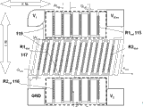
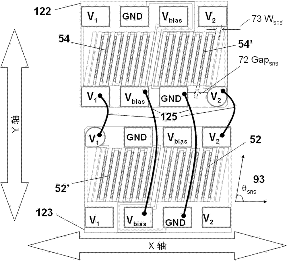
图19是使用如图16和图13中的磁电阻元件70的推挽全桥传感器芯片的布局图。两个相同的芯片122和123是由同一块晶圆切割制成,被封装为一个传感器。两块芯片相对于Z轴相互旋转180°,其敏感面为X-Y平面。每一个芯片都有两个电隔离的磁电阻感应臂。
FIG. 19 is a layout diagram of a push-pull full-bridge sensor chip using the
推挽全桥传感器50通过引线125进行电连接。矩形的焊盘位于每个芯片的边缘,除了一个焊线位是圆形的以便于直观地确定每一个芯片焊盘的数量和方向。每一个电路的节点都有两个焊盘(总共有8个),一个用于内部的桥式连接,另一个用于与外部的器件连接。这使得位于芯片122顶部的焊盘可以通过引线连接到引线框的封装引脚和PCB上。
The push-pull full-
在所给的芯片中,元件的长轴沿着敏感轴方向。芯片上的条形永磁体呈倾斜设置,具有宽度W73,两块磁体间的间距为Gap72,倾斜角为θsns93。这些磁体提供了磁偏置场以饱和感应元件,当附加提供的Hoff满足Hoff-Ho > Hsat时。这是一个推挽桥展示其线性工作状态所必须的。右上方的负的磁电阻54'连接于GND和V2之间。左上方负的磁电阻54连接在Vbias和V1之间。磁电阻54和54'的R-Hsense响应曲线见中插图120,在外场Hsense的负的方向具有高阻态。
In a given chip, the long axis of the element is along the sensitive axis. The bar-shaped permanent magnets on the chip are inclined and have a width of W73, the distance between two magnets is Gap72, and the inclination angle is
图20是参考全桥传感器51的布局图,该参考桥设置了感应臂和参考臂间具有不同宽度、角度以及间隔的倾斜的条形永磁体,如图所示,构成参考臂的磁电阻元件的长轴垂直于敏感轴Y轴,在X轴方向上的长度要大于构成感应臂的磁电阻元件,使参考臂平行于敏感方向的退磁效应要远大于感应臂。在这个设计中,参考臂和感应臂在基片上一次性制备完成,可通过片上沉积导线或引线键合进行电连构成电桥结构,从该晶圆上切割制成的参考全桥传感器位于一个基片上,这种结构我们称之为“单片式传感器”,单片式传感器相对于多芯片封装的传感器来说,简化了制备工艺的同时缩小了传感器的体积。MTJ元件串位于不同倾角的条形永磁体的中间,115、116、117和118为电桥的桥臂。在这个设计中,θref=π/2,θsns在π/4和π/2之间。使偏移归零的优化可以同时调整参考臂和感应臂MTJ元件的数量,或只是对参考臂或感应臂偏移优化。如图虚线所示的矩形屏蔽层119也是可选的方法。屏蔽层的作用是进一步降低参考臂115和116的有效灵敏度。
Fig. 20 is a layout diagram of a reference full-
其余桥式磁场传感器的布局图与上述相似,在此就不再累述了。 The layout diagrams of the rest of the bridge-type magnetic field sensors are similar to those described above, and will not be repeated here.
用于测量磁场的磁电阻传感器能够实现大规模生产,测量磁场的灵敏度更高,同时具备功耗低、尺寸小的特点。 Magneto-resistive sensors for measuring magnetic fields can be mass-produced, have higher sensitivity for measuring magnetic fields, and have the characteristics of low power consumption and small size.
上述实施例只为说明本实用新型的技术构思及特点,其目的在于让熟悉此项技术的人士能够了解本实用新型的内容并据以实施,并不能以此限制本实用新型的保护范围。凡根据本实用新型精神实质所作的等效变化或修饰,都应涵盖在本实用新型的保护范围之内。 The above-mentioned embodiments are only to illustrate the technical concept and characteristics of the present utility model, and its purpose is to enable those familiar with this technology to understand the content of the present utility model and implement it accordingly, and not to limit the protection scope of the present utility model. All equivalent changes or modifications made according to the spirit of the utility model shall fall within the protection scope of the utility model.
Claims (42)
Priority Applications (1)
| Application Number | Priority Date | Filing Date | Title |
|---|---|---|---|
| CN 201220053923 CN202494772U (en) | 2012-02-20 | 2012-02-20 | Magnetoresistive sensor for measuring magnetic field |
Applications Claiming Priority (1)
| Application Number | Priority Date | Filing Date | Title |
|---|---|---|---|
| CN 201220053923 CN202494772U (en) | 2012-02-20 | 2012-02-20 | Magnetoresistive sensor for measuring magnetic field |
Publications (1)
| Publication Number | Publication Date |
|---|---|
| CN202494772U true CN202494772U (en) | 2012-10-17 |
Family
ID=47000995
Family Applications (1)
| Application Number | Title | Priority Date | Filing Date |
|---|---|---|---|
| CN 201220053923 Expired - Lifetime CN202494772U (en) | 2012-02-20 | 2012-02-20 | Magnetoresistive sensor for measuring magnetic field |
Country Status (1)
| Country | Link |
|---|---|
| CN (1) | CN202494772U (en) |
Cited By (5)
| Publication number | Priority date | Publication date | Assignee | Title |
|---|---|---|---|---|
| CN102565727A (en) * | 2012-02-20 | 2012-07-11 | 江苏多维科技有限公司 | Magnetic resistance sensor for measuring magnetic field |
| WO2015010649A1 (en) * | 2013-07-26 | 2015-01-29 | 江苏多维科技有限公司 | Single reluctance tmr magnetic field sensor chip and currency detector magnetic head |
| CN105093139A (en) * | 2015-06-09 | 2015-11-25 | 江苏多维科技有限公司 | Push-pull X shaft magneto-resistor sensor |
| CN105866712A (en) * | 2015-01-21 | 2016-08-17 | 中国科学院上海微系统与信息技术研究所 | Superconducting quantum interference device |
| WO2017173992A1 (en) * | 2016-04-06 | 2017-10-12 | 江苏多维科技有限公司 | Anisotropic magnetoresistance (amr) sensor not requiring set/reset device |
-
2012
- 2012-02-20 CN CN 201220053923 patent/CN202494772U/en not_active Expired - Lifetime
Cited By (12)
| Publication number | Priority date | Publication date | Assignee | Title |
|---|---|---|---|---|
| CN102565727A (en) * | 2012-02-20 | 2012-07-11 | 江苏多维科技有限公司 | Magnetic resistance sensor for measuring magnetic field |
| WO2013123873A1 (en) * | 2012-02-20 | 2013-08-29 | 江苏多维科技有限公司 | Magneto-resistive sensor for measuring magnetic field |
| CN102565727B (en) * | 2012-02-20 | 2016-01-20 | 江苏多维科技有限公司 | For measuring the magnetic resistance sensor in magnetic field |
| US11287490B2 (en) | 2012-02-20 | 2022-03-29 | MultiDimension Technology Co., Ltd. | Magnetoresistive sensor with sensing elements and permanent magnet bars oriented at non-orthogonal and non-parallel angles with respect to the sensing direction of the sensing elements |
| WO2015010649A1 (en) * | 2013-07-26 | 2015-01-29 | 江苏多维科技有限公司 | Single reluctance tmr magnetic field sensor chip and currency detector magnetic head |
| US9804235B2 (en) | 2013-07-26 | 2017-10-31 | MultiDimension Technology Co., Ltd. | Single magnetoresistor TMR magnetic field sensor chip and magnetic currency detector head |
| CN105866712A (en) * | 2015-01-21 | 2016-08-17 | 中国科学院上海微系统与信息技术研究所 | Superconducting quantum interference device |
| CN105866712B (en) * | 2015-01-21 | 2018-07-06 | 中国科学院上海微系统与信息技术研究所 | A kind of superconducting quantum interference device |
| CN105093139A (en) * | 2015-06-09 | 2015-11-25 | 江苏多维科技有限公司 | Push-pull X shaft magneto-resistor sensor |
| CN105093139B (en) * | 2015-06-09 | 2017-11-24 | 江苏多维科技有限公司 | A kind of push-pull type X-axis magnetic resistance sensor |
| WO2017173992A1 (en) * | 2016-04-06 | 2017-10-12 | 江苏多维科技有限公司 | Anisotropic magnetoresistance (amr) sensor not requiring set/reset device |
| US11346901B2 (en) | 2016-04-06 | 2022-05-31 | MultiDimension Technology Co., Ltd. | Anisotropic magnetoresistive (AMR) sensor without set and reset device |
Similar Documents
| Publication | Publication Date | Title |
|---|---|---|
| CN102565727B (en) | For measuring the magnetic resistance sensor in magnetic field | |
| CN102590768B (en) | Magneto-resistance magnetic field gradient sensor | |
| EP2752675B1 (en) | Mtj three-axis magnetic field sensor and encapsulation method thereof | |
| CN102426344B (en) | Three-axis magnetic field sensor | |
| CN102419393B (en) | Current sensor | |
| CN102621504B (en) | Monolithic reference full bridge magnetic field sensor | |
| JP6193212B2 (en) | Single chip 2-axis bridge type magnetic field sensor | |
| CN102435963B (en) | Monolithic dual-axis bridge-type magnetic field sensor | |
| CN104104376B (en) | Push-pull type chip overturns half-bridge reluctance switch | |
| CN102540112B (en) | Single chip pull-push bridge type magnetic field sensor | |
| CN202210144U (en) | Single-chip reference full-bridge magnetic field sensor | |
| JP2014512003A (en) | Single-chip push-pull bridge type magnetic field sensor | |
| WO2015058632A1 (en) | Push-pull bridge-type magnetic sensor for high-intensity magnetic fields | |
| CN202494772U (en) | Magnetoresistive sensor for measuring magnetic field | |
| CN202794487U (en) | Magneto-resistor magnetic field gradient sensor | |
| CN202421321U (en) | Current sensor | |
| CN203233390U (en) | Push-pull type half-bridge reluctance switch with overturning chips | |
| CN202210145U (en) | MTJ triaxial magnetic field sensor |
Legal Events
| Date | Code | Title | Description |
|---|---|---|---|
| C14 | Grant of patent or utility model | ||
| GR01 | Patent grant | ||
| CX01 | Expiry of patent term |
Granted publication date: 20121017 |
|
| CX01 | Expiry of patent term |