CN202494511U - Signal collector for realizing automatic acquisition of vibration signals - Google Patents
Signal collector for realizing automatic acquisition of vibration signals Download PDFInfo
- Publication number
- CN202494511U CN202494511U CN201220025456XU CN201220025456U CN202494511U CN 202494511 U CN202494511 U CN 202494511U CN 201220025456X U CN201220025456X U CN 201220025456XU CN 201220025456 U CN201220025456 U CN 201220025456U CN 202494511 U CN202494511 U CN 202494511U
- Authority
- CN
- China
- Prior art keywords
- signal
- processing unit
- vibration
- vibration signal
- picker
- Prior art date
- Legal status (The legal status is an assumption and is not a legal conclusion. Google has not performed a legal analysis and makes no representation as to the accuracy of the status listed.)
- Expired - Fee Related
Links
- 238000012545 processing Methods 0.000 claims abstract description 54
- 238000006243 chemical reaction Methods 0.000 claims abstract description 26
- 238000004891 communication Methods 0.000 claims description 28
- 230000005540 biological transmission Effects 0.000 abstract description 14
- 230000003321 amplification Effects 0.000 abstract description 5
- 238000003199 nucleic acid amplification method Methods 0.000 abstract description 5
- 239000003990 capacitor Substances 0.000 description 12
- 238000012360 testing method Methods 0.000 description 7
- 238000010586 diagram Methods 0.000 description 5
- 238000000034 method Methods 0.000 description 3
- 238000001514 detection method Methods 0.000 description 2
- 230000007613 environmental effect Effects 0.000 description 2
- 238000012544 monitoring process Methods 0.000 description 2
- 230000009286 beneficial effect Effects 0.000 description 1
- 238000013461 design Methods 0.000 description 1
- DMBHHRLKUKUOEG-UHFFFAOYSA-N diphenylamine Chemical compound C=1C=CC=CC=1NC1=CC=CC=C1 DMBHHRLKUKUOEG-UHFFFAOYSA-N 0.000 description 1
- 238000005516 engineering process Methods 0.000 description 1
- 239000000835 fiber Substances 0.000 description 1
- 238000007689 inspection Methods 0.000 description 1
- 238000012986 modification Methods 0.000 description 1
- 230000004048 modification Effects 0.000 description 1
- 238000012797 qualification Methods 0.000 description 1
Images


Landscapes
- Arrangements For Transmission Of Measured Signals (AREA)
Abstract
The utility model discloses a signal collector for realizing automatic acquisition of vibration signals, belonging to the field of signal acquisition. The signal collector comprises a sensor, a processing unit, a differential amplification circuit, an analog-to-digital conversion unit, a vibrator, a wireless transmission module and a power supply circuit. The power supply circuit provides power for the signal collector, the processing unit sends a control signal to the vibrator which drives the vibration of an object, the sensor acquires vibration signals of the object and sends the vibration signals to the differential amplification circuit for differential amplification processing, the analog-to-digital conversion unit converts the processed vibration signals into vibration digital signals, which are then modulated by the processing unit and sent by the wireless transmission module. By adopting the signal collector provided by the utility model, automatic acquisition of vibration signals is realized.
Description
Technical field
The utility model relates to a kind of signal picker, particularly a kind of signal picker of realizing that vibration signal is gathered automatically.
Background technology
As shown in Figure 1; Present signal picker great majority are made up of sensor and processing unit; Sensor is used for acquired signal and this signal is sent to processing unit; Again by processing unit to this signal amplify, analog to digital conversion and modulation treatment, the signal after will modulating then sends with the mode of wire transmission.
Along with the range of application expansion of signal picker, traditional signals collecting box can not satisfy current engineering demand.For example; Gathering the vibration signal of certain object under the vibration situation, thereby when detecting the self performance of this object, the testing staff need buy a Vib. again; This Vib. is connected with object; And only under the testing staff starts the situation of this Vib., just can realize vibration signals, promptly in whole vibration signals process, must have the testing staff to monitor at the scene, can't realize the automatic collection of vibration signal.
The utility model content
The goal of the invention of the utility model is: to the problem of above-mentioned existence, a kind of signal picker of realizing that vibration signal is gathered automatically is provided.
The technical scheme that the utility model adopts is such: a kind of signal picker of realizing that vibration signal is gathered automatically, comprise sensor, processing unit and power circuit, and wherein said sensor is used to gather vibration signal and sends to this processing unit;
Said processing unit is used for this vibration signal is carried out modulation treatment;
Said power circuit is used for to this signal picker power supply being provided;
It is characterized in that: go back the involving vibrations device, wherein the control signal output ends of this processing unit connects the input end of this Vib.;
Said processing unit is used to transmit control signal to this Vib.;
Said Vib. is used for after receiving this control signal, driving object vibration.
This signal picker also comprises wireless transport module, and this processing unit is used for sending this vibration signal after modulation through this wireless transport module.
This signal picker also comprises the radio communication detecting unit; Be used to detect wireless communication state; And when wireless communication state is good, send enable signal to this processing unit, this processing unit sends this vibration signal after modulation through this wireless transport module after receiving this enable signal.
This signal picker also comprises differential amplifier circuit, is used for receiving vibration signal and this vibration signal being carried out the difference processing and amplifying from this sensor.
This signal picker also comprises AD conversion unit, is used for this vibration signal after the difference processing and amplifying is carried out analog to digital conversion, converts the vibration digital signal to.
In sum, owing to adopted technique scheme, the beneficial effect of the utility model is:
1, when gathering the vibration signal of object, must adopt Vib. and traditional signal picker to carry out artificial field monitoring collection simultaneously at present; The utility model then is integrated in this Vib. in the signal picker, the automatic collection that period that transmits control signal through processing unit in the modelled signal collector and frequency can realize vibration signal;
2, traditional signal picker adopts the mode of wire transmission to transmit this vibration signal more; The utility model has then increased Wireless transmission mode; Increased the radio communication detecting unit that is used to detect wireless communication state in addition; And this radio detection unit sends enable signal to this processing unit when wireless communication state is good; Only after the test side of processing unit receives this enable signal, just send this vibration signal, thereby guaranteed stability of data transmission and integrality through wireless transport module;
3, traditional signal picker adopts the modes of directly gathering more when gathering vibration signal; And only vibration signal is realized amplification, analog to digital conversion and modulation treatment by processing unit; The mode that the utility model then adopts difference to gather has effectively solved the influence of difference mode signal to data.
Description of drawings
Fig. 1 is the circuit theory diagrams of traditional signal picker;
Fig. 2 is the circuit theory diagrams of the utility model;
Fig. 3 is the circuit diagram of power circuit among first embodiment of the utility model;
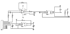
Fig. 4 is the circuit diagram of differential amplifier circuit among first embodiment of the utility model, AD conversion unit and radio communication detecting unit;
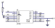
Fig. 5 is the circuit diagram of processing unit among first embodiment of the utility model.
Embodiment
Below in conjunction with accompanying drawing, the utility model is done detailed explanation.
For the purpose, technical scheme and the advantage that make the utility model is clearer,, the utility model is further elaborated below in conjunction with accompanying drawing and embodiment.Should be appreciated that specific embodiment described herein only in order to explanation the utility model, and be not used in qualification the utility model.
As shown in Figure 2; This signal picker is made up of piezoelectric transducer, processing unit, Vib., differential amplifier circuit, analog to digital conversion circuit, wireless transport module, radio communication detecting unit and power circuit; Wherein this power circuit is used for to this signal picker power supply being provided; The control signal output ends of processing unit connects Vib.; The output terminal of piezoelectric transducer connects differential amplifier circuit, and the output terminal of differential amplifier circuit connects AD conversion unit, the signal input part of the output terminal connection processing unit of AD conversion unit; The test side of the output terminal connection processing unit of radio communication detecting unit, and the signal output part of processing unit connects this wireless transport module.When gathering the vibration signal of object under the vibration situation; Processing unit is used to transmit control signal to Vib.; Vib. drives object vibration, and this piezoelectric transducer is gathered the vibration signal of this object under the vibration situation, and this differential amplifier circuit carries out the difference processing and amplifying to this vibration signal; Vibration signal after this AD conversion unit amplifies difference converts the vibration digital signal to; Processing unit is used for this vibration digital signal is carried out modulation treatment, and this processing unit is under the good situation of radio communication detecting unit display radio communication conditions, and the vibration digital signal after will modulating through wireless transport module sends.Differential amplifier circuit, analog to digital conversion circuit, processing unit, wireless transport module, radio communication detecting unit and power circuit all are packaged in the collecting cassette in the utility model; This piezoelectric transducer and Vib. then are arranged on outside the collecting cassette, are used for fixing on object under test.This piezoelectric transducer adopts SMD piezoelectric sensor; Its volume is little, be convenient to install; The collecting sensor signal line is guided to and is buried in the underground collecting cassette such as the vibration signal of gathering railroad track the time, and collecting cassette is buried in underground, more helps signal and does not receive interference from outside signals.
At first; When gathering the vibration signal of object, must adopt Vib. and traditional signal picker to carry out artificial field monitoring collection simultaneously at present; The utility model then is integrated in this Vib. in the signal picker, the automatic collection that period that transmits control signal through processing unit in the modelled signal collector and frequency can realize vibration signal.The utility model is particularly useful for the frequent situation of gathering the object vibration signal of needs, such as the vibration signal of gathering railroad track.
Secondly; Traditional signal picker is the modes of directly gathering that adopt when gathering vibration signal more; And only vibration signal is realized amplification, analog to digital conversion and modulation treatment by processing unit; The mode that the utility model then adopts difference to gather has effectively solved the influence of difference mode signal to data, and adopts effective shielding measure to improve EMC (the Electro Magnetic Compatibility of system; Electro Magnetic Compatibility) performance still can be gathered and judge the utility model accurately to signal under harsh environmental conditions.
At last; Traditional signal picker adopts the mode of wire transmission to transmit this vibration signal more; The utility model has then increased Wireless transmission mode; Increased the radio communication detecting unit that is used to detect wireless communication state in addition; And this radio detection unit sends enable signal to this processing unit when wireless communication state is good, only after the test side of processing unit receives this enable signal, just sends this vibration signal through wireless transport module, thereby has guaranteed stability of data transmission and integrality.In first embodiment of the utility model; The wire transmission mode of vibration signal can include but not limited to high voltage power line, power line Support Level, set up special-purpose additional communication circuit, fiber plant order wire, utilize signal lamp existing communication circuit, and wireless transmission method can include but not limited to satellite communications such as WIFI, bluetooth, zigbee, radio frequency and gps satellite, Galilean satellite system and Chinese big-dipper satellite.When measuring the vibration signal of railroad track, preferably adopting the high voltage power line is this vibration signal of wire transmission media transmission, by this high voltage power line this vibration signal of form transmission with power line carrier.
In first embodiment of the utility model; As shown in Figure 3; This power circuit comprises 2.5V parallel voltage-stabilizing diode U4 and power conversion chip U6; Wherein power supply VCC connects the input end IN of 2.5V parallel voltage-stabilizing diode U4, the positive pole of polarity diode C8 respectively through resistance R 9; 2.5V the pressure feedback port VF of parallel voltage-stabilizing diode U4 connects its input end IN and passes through resistance R 11 ground connection, the earth terminal GND of this 2.5V parallel voltage-stabilizing diode U4 and the equal ground connection of negative pole of polarity diode C8 through resistance R 10.This power supply VCC is V+ through the voltage of resistance R 9 outputs, and this voltage V+ offers port 3 and the AD conversion unit U3 of data-interface CON shown in Figure 4.
The port CAP+ of power conversion chip U6 connects the negative pole connectivity port CAP-of anodal and this polar capacitor C10 of polar capacitor C10; Port V+ connects power supply VCC and passes through capacitor C 3 ground connection; Port VOUT connects power supply-VCC and connects the negative pole of polar capacitor C11, the plus earth of this polar capacitor C11.The voltage of the port NC output of this power conversion chip U6 is V33, and this voltage V33 offers radio communication detecting unit U2 shown in Figure 4, AD conversion unit U3 and processing unit U5 shown in Figure 5.
Adopt above-mentioned power circuit; The Wen Bo that has reduced external interference as much as possible and caused is to the influence of system signal; Improve the reliability of image data, and processing unit U5 implements inspection to the electric power thus supplied of this power circuit, to guarantee the stability of this signal picker power supply.The model of the 2.5V parallel voltage-stabilizing diode U4 of above-mentioned power circuit employing in the present embodiment is LM336, and the model that this power conversion chip U6 adopts is ME7660.
As shown in Figure 4, the port one of data-interface CON connects the reverse input end of differential amplifier circuit through resistance R 2, and connects the positive input of differential amplifier circuit successively through resistance R 2, capacitor C 1; The positive-negative power input end of this differential amplifier circuit connect respectively power supply VCC ,-VCC; First end of differential amplifier circuit connects the 8th end and five terminal ground connection through resistance R 1, has improved the EMC performance of system through the shielding measure of this design, and system still can be gathered signal and judge under harsh environmental conditions accurately.The output terminal of differential amplifier circuit is through the port VIN+ of resistance R 4 connection AD conversion unit U3, and the output terminal of differential amplifier circuit is also successively through resistance R 4, capacitor C 2 ground connection.The port VIN-ground connection of AD conversion unit; And port VDD connects power supply V+ and passes through capacitor C 5 ground connection; The port SCL of this AD conversion unit U3, SDA connect power supply V33 through resistance R 7, R8 respectively, and this port SCL, SDA connect P1.2 and the P1.3 of processing unit U5 shown in Figure 5 as the output terminal of AD conversion unit U3.
The port 4 of data-interface CON connects the port VIN of radio communication detecting unit U2 and connects the positive pole of polar capacitor C7; The minus earth of polar capacitor C7; The port VIN of this radio communication detecting unit U2 connects power supply V33 and port RSN connects power supply V33 through resistance R 5; The port VOUT of this radio communication detecting unit U2 connects the positive pole of polar capacitor C9; The positive pole of this polar capacitor C9 also connects power supply VCC and minus earth, and the Enable Pin EN of this radio communication detecting unit U2 connects the P0.3 of processing unit U5 shown in Figure 5, and whether good enable signal sends to processing unit U5 to be used to represent wireless communication state.
The model of this differential amplifier circuit employing is AD620BR in the present embodiment, and the model that AD conversion unit adopts is ADS1100, and the model that this radio communication detecting unit U2 adopts is SP6200.
As shown in Figure 5, the P0.1 of processing unit U5 connects the port 7 of data-interface CON, is used for the control signal of control Vib. vibration is sent to Vib.; The port TXD of this processing unit U5, RXD connect the port 9,10 of data-interface CON respectively, are used for piezoelectric transducer is carried out read-write operation.The model of this processing unit employing is LPC915 in the present embodiment.
The above is merely the preferred embodiment of the utility model; Not in order to restriction the utility model; Any modification of being done within all spirit and principles at the utility model, be equal to replacement and improvement etc., all should be included within the protection domain of the utility model.
Claims (5)
1. a signal picker of realizing that vibration signal is gathered automatically comprises sensor, processing unit and power circuit, and wherein said sensor is used to gather vibration signal and sends to this processing unit;
Said processing unit is used for this vibration signal is carried out modulation treatment;
Said power circuit is used for to this signal picker power supply being provided;
It is characterized in that: go back the involving vibrations device, wherein the control signal output ends of this processing unit connects the input end of this Vib.;
Said processing unit is used to transmit control signal to this Vib.;
Said Vib. is used for after receiving this control signal, driving object vibration.
2. the signal picker that realization vibration signal according to claim 1 is gathered automatically is characterized in that: also comprise wireless transport module, this processing unit is used for sending this vibration signal after modulation through this wireless transport module.
3. the signal picker that realization vibration signal according to claim 2 is gathered automatically; It is characterized in that: also comprise the radio communication detecting unit; Be used to detect wireless communication state; And when wireless communication state is good, send enable signal to this processing unit, this processing unit sends this vibration signal after modulation through this wireless transport module after receiving this enable signal.
4. the signal picker of gathering automatically according to any one described realization vibration signal in the claim 1~3 is characterized in that: also comprise differential amplifier circuit, be used for receiving vibration signal and this vibration signal being carried out the difference processing and amplifying from this sensor.
5. the signal picker that realization vibration signal according to claim 4 is gathered automatically is characterized in that: also comprise AD conversion unit, be used for this vibration signal after the difference processing and amplifying is carried out analog to digital conversion, convert the vibration digital signal to.
Priority Applications (1)
| Application Number | Priority Date | Filing Date | Title |
|---|---|---|---|
| CN201220025456XU CN202494511U (en) | 2012-01-19 | 2012-01-19 | Signal collector for realizing automatic acquisition of vibration signals |
Applications Claiming Priority (1)
| Application Number | Priority Date | Filing Date | Title |
|---|---|---|---|
| CN201220025456XU CN202494511U (en) | 2012-01-19 | 2012-01-19 | Signal collector for realizing automatic acquisition of vibration signals |
Publications (1)
| Publication Number | Publication Date |
|---|---|
| CN202494511U true CN202494511U (en) | 2012-10-17 |
Family
ID=47000736
Family Applications (1)
| Application Number | Title | Priority Date | Filing Date |
|---|---|---|---|
| CN201220025456XU Expired - Fee Related CN202494511U (en) | 2012-01-19 | 2012-01-19 | Signal collector for realizing automatic acquisition of vibration signals |
Country Status (1)
| Country | Link |
|---|---|
| CN (1) | CN202494511U (en) |
Cited By (2)
| Publication number | Priority date | Publication date | Assignee | Title |
|---|---|---|---|---|
| CN108955554A (en) * | 2018-08-01 | 2018-12-07 | 姜忠华 | A kind of Beidou number natural disaster monitoring management system |
| CN114894294A (en) * | 2022-05-15 | 2022-08-12 | 南京理工大学紫金学院 | Small-size low-noise vibration sensor |
-
2012
- 2012-01-19 CN CN201220025456XU patent/CN202494511U/en not_active Expired - Fee Related
Cited By (2)
| Publication number | Priority date | Publication date | Assignee | Title |
|---|---|---|---|---|
| CN108955554A (en) * | 2018-08-01 | 2018-12-07 | 姜忠华 | A kind of Beidou number natural disaster monitoring management system |
| CN114894294A (en) * | 2022-05-15 | 2022-08-12 | 南京理工大学紫金学院 | Small-size low-noise vibration sensor |
Similar Documents
| Publication | Publication Date | Title |
|---|---|---|
| CN101725366B (en) | Position detecting device for coal winning machine on integrated excavating coal face | |
| CN104581058A (en) | Fan signal acquiring device | |
| CN202494511U (en) | Signal collector for realizing automatic acquisition of vibration signals | |
| CN106230376A (en) | A kind of Power Line Inspection System based on the Big Dipper | |
| CN204065423U (en) | Field discrete earthquake digital recording equipment | |
| CN211905489U (en) | Steel rail current and voltage acquisition device | |
| CN104901682A (en) | M-Bus host circuit | |
| CN103925949B (en) | Agriculture detection device | |
| CN205404716U (en) | Fault detection device and object transmission detection system of correlation sensor | |
| CN113691955B (en) | Communication method and system for detection data of air purifier | |
| CN109632084A (en) | A kind of vacuum magnetic levitation pepe monitoring system | |
| CN104502713A (en) | Low-power-consumption conductivity sensor applied to wireless transmission system | |
| CN106773967B (en) | Vibrating wire acquisition instrument with vibrating wire sensor diagnosis function | |
| CN202433039U (en) | Environmental parameter measuring device based on RFID (radio frequency identification devices) | |
| CN212723394U (en) | Thing reconnaissance sensor based on wireless transmission | |
| CN104181332A (en) | Wireless posture/impact measurement recording system | |
| CN210183328U (en) | Cascade type cableless probe rod communication circuit | |
| CN103389512A (en) | Digital collection and transmission circuit for near-field subwaves and auxiliary signals of air gun earthquake focus | |
| CN210777026U (en) | Data acquisition and transmission device | |
| CN209895491U (en) | Information transmission system for underground control | |
| CN211346908U (en) | Information monitoring system of high-voltage power equipment | |
| CN107241551A (en) | A kind of intelligent charging stake project installation instrument | |
| CN202041872U (en) | Automatic power control device | |
| CN201953377U (en) | Signal transmission device for coal seam gas well detection signal | |
| CN202686391U (en) | Railway train approach monitoring device based on geomagnetic anomaly |
Legal Events
| Date | Code | Title | Description |
|---|---|---|---|
| C14 | Grant of patent or utility model | ||
| GR01 | Patent grant | ||
| C17 | Cessation of patent right | ||
| CF01 | Termination of patent right due to non-payment of annual fee |
Granted publication date: 20121017 Termination date: 20140119 |