CN202494431U - High-speed photoelectric non-contact displacement deflection measuring device - Google Patents
High-speed photoelectric non-contact displacement deflection measuring device Download PDFInfo
- Publication number
- CN202494431U CN202494431U CN2012200657170U CN201220065717U CN202494431U CN 202494431 U CN202494431 U CN 202494431U CN 2012200657170 U CN2012200657170 U CN 2012200657170U CN 201220065717 U CN201220065717 U CN 201220065717U CN 202494431 U CN202494431 U CN 202494431U
- Authority
- CN
- China
- Prior art keywords
- led light
- main frame
- speed
- emitting device
- photoelectricity
- Prior art date
- Legal status (The legal status is an assumption and is not a legal conclusion. Google has not performed a legal analysis and makes no representation as to the accuracy of the status listed.)
- Expired - Fee Related
Links
Images
Landscapes
- Length Measuring Devices By Optical Means (AREA)
Abstract
The utility model relates to a high-speed photoelectric non-contact displacement deflection measuring device, comprising a bright LED light-emitting device, a sighting device, a photoelectric receiving host and a computer which is preloaded with special data acquisition and processing software. The photoelectric receiving host comprises an optical path switching mechanism, a high-speed CCD image sensor and a high-precision angle sensor. The high-precision angle sensor is mounted on a vertical rotary shaft of a tripod. The high-speed CCD image sensor is arranged on the high-precision angle sensor. The optical path switching mechanism is arranged on a side of the high-speed CCD image sensor and image points which are formed on the high-speed CCD image sensor are thus controlled. The sighting device is provided on the bright LED light-emitting device. The photoelectric receiving host is communicated with the computer via a data bus. The device can be used for measuring and monitoring bridge deflection, ground subsidence, building subsidence and moving, and has the advantages of wide range of use, high-speed non-contact measurement, convenient installation and debugging and the like.
Description
Technical field
The utility model relates to a kind of measurement mechanism, relates in particular to a kind of photo-electric non-cpntact measurement device that is used in the building engineering survey field.
Background technology
Each item infrastructure constructions such as road and rail are located in the Chinese national economy construction always in occupation of critical role.Simultaneously, the various building structures in infrastructure are related to the healthy and sustainable development of national economy and the people's the security of the lives and property especially like the normal operation of bridge, building, dam etc.
Guarantee that the important means that these infrastructure can normally be runed is exactly the measurement to its index of correlation.As everyone knows; In the building engineering survey field; Detection and the more traditional method of monitoring rate to distortion, displacement are to use spirit-leveling instrument, transit or total powerstation etc.; But under the situation of some special occasions or specific (special) requirements, gather change in displacement etc. like high-speed and continuous, these conventional instruments can not provide good solution.
In recent years; Domestic and international association area has developed some in succession and has utilized special-purpose displacement measuring devices such as image method, Principles of Laser; Verify through the engineering field survey; More or less there are some problems, relatively poor like the coarse ease for use that causes of structural design own, lower etc. than the precision that is easier to be affected by the external environment.
The utility model content
For overcoming above-mentioned defective, it is with in extensive range that the purpose of the utility model provides a kind of, and existing similar detection means possesses higher precision, convenient more easy-to-use use-pattern, photo-electric noncontact digit shift measurement apparatus and method at a high speed.
For achieving the above object, the utility model adopts following technical scheme:
A kind of high speed optoelectronic formula noncontact displacement deflection measuring apparatus; Comprise that high bright LED light-emitting device, alignment clamp, photoelectricity receive main frame and computing machine; It is characterized in that said photoelectricity receives main frame and comprises light path switching mechanism, high-speed CCD imageing sensor and high-precision angle sensor; High-precision angle sensor is installed in the vertical rotating shaft of tripod, and the high-speed CCD imageing sensor is arranged on the high-precision angle sensor, and the light path switching mechanism is arranged on high-speed CCD imageing sensor side and can controls the picture point that forms on the high-speed CCD imageing sensor; Alignment clamp places on the high bright LED light-emitting device, and photoelectricity receives main frame and carries out communication through data bus and computing machine.
Described light path switching mechanism is plug-type.
The mounting plane quadrature of described alignment clamp and LED light-emitting device, the LED light that the LED light-emitting device sends when measuring with assurance is parallel with the optical axis that photoelectricity receives main frame.
The data bus that carries out data communication with said computing machine passes from the inner light path of photoelectricity reception main frame.
When using this device, adopt following method:
1) at first the bright LED of the height device of giving out light firmly is installed on the testee, regulates the light level of high bright LED light-emitting device and vertical direction of illumination, sight the main frame position through sighting device;
2) next adjust main frame level and luffing angle, make main frame sight high bright LED light-emitting device, and on the high-speed CCD imageing sensor, form effective picture point through plug-type light path switching mechanism.
3) set the correlation parameter of current sampling rate and brightness of image, contrast through software interface, import the current current main frame luffing angle that obtains by high-precision angle sensor, calculate current optical system magnification.
4) free displacement or displacement, high bright LED light-emitting device movement therewith mounted thereto, the also corresponding real time altering of picture point position when object under test.View data always gets into computing machine through the computer interface transmission through data.
5) special software obtains picture point pixel variable quantity through calculating in real time, further draws the actual size of ohject displacement or vibration through the magnification of light path system, and high-speed real-time is drawn displacement or vibration time history plot table.Can be special-purpose file layout with data storage simultaneously,, can further improve the reliability and the precision of measurement data through post-processed or repeatedly measurement contrast.
Compared with prior art, the present invention has following advantage and characteristics:
1, the light path switching mechanism employing of photoelectricity reception main frame is plug-type, and simple and reliable on the structure, ergonomic can provide good operating experience.
2, on the high bright LED light-emitting device alignment clamp is set, makes that LED light can to receive main frame light path system optical axis parallel with photoelectricity, thereby the light intensity that the high-speed CCD imageing sensor is received is the strongest, can carry out high-speed real-time and measure, and has greatly improved sampling rate.
3, high-precision angle sensor combines the alignment clamp on the high bright LED light-emitting device, has further improved the computational accuracy of on-the-spot light path system magnification, and then improves measuring accuracy.
4, data bus is connected with computer interface after instrument internal runs through light path, is skillfully constructed, and is reasonable in design, simple in structure.Neither influence the operate as normal of light path, data in high speed transmission in the time of guaranteeing to measure again simultaneously.
Description of drawings
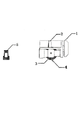
Fig. 1 is emission of the present invention and photoelectric receiving arrangement synoptic diagram;
Fig. 2 is a system construction synoptic diagram of the present invention.
Among the figure, light path switching mechanism 1, high-speed CCD imageing sensor 2, high precision angle detection device 3, data bus 4, alignment clamp 5, photoelectricity receive main frame 6, tripod 7, computing machine 8.
Embodiment
Below in conjunction with description of drawings and embodiment the utility model is further described:
Like Fig. 1, shown in 2; A kind of high speed optoelectronic formula noncontact displacement deflection measuring apparatus; Comprise that high bright LED light-emitting device, alignment clamp 5, photoelectricity receive the computing machine 8 of main frame 6 and prepackage exclusive data acquisition process software; Said photoelectricity receives main frame 6 and comprises light path switching mechanism 1, high-speed CCD imageing sensor 2 and high-precision angle sensor 3; High-precision angle sensor 3 is installed in the vertical rotating shaft of tripod 7, and high-speed CCD imageing sensor 2 is arranged on the high-precision angle sensor 3, and light path switching mechanism 1 is arranged on high-speed CCD imageing sensor 2 sides and can controls the picture point that forms on the high-speed CCD imageing sensor 2; Alignment clamp 5 places on the high bright LED light-emitting device, and photoelectricity receives main frame 6 and carries out communication through data bus 4 and computing machine 8.Described light path switching mechanism 1 is plug-type, the mounting plane quadrature of described alignment clamp 5 and LED light-emitting device, and the LED light that the LED light-emitting device sends when measuring with assurance is parallel with the optical axis that photoelectricity receives main frame 6.The data bus 4 that described and computing machine 8 carries out data communication passes from the light path of photoelectricity reception main frame 6 inside.
During use, alignment clamp 5 is made on the high bright LED light-emitting device that is installed on the testee, sight photoelectricity and receive main frame 6; Be positioned at the level and the angle of pitch of the reception main frame 6 on the tripod 7 through adjustment, and use plug-type light path switching mechanism 1 to make the LED light-emitting device on high-speed CCD imageing sensor 2, form effective picture point;
High bright LED light-emitting device can along with the testee displacement with or vibration be synchronized with the movement, also corresponding change in location can take place through the picture point of optical system imaging on high-speed CCD imageing sensor 2 simultaneously;
High-speed CCD imageing sensor 2 is sent to the view data and the main frame angle of pitch in the computing machine 8 through data bus 4 with high-precision angle sensor 3 in real time.
Special software calculates the view data of obtaining, and obtains picture point pixel variable quantity.Can draw the actual size of ohject displacement or vibration according to the magnification of light path system.The current angle of pitch that obtains through high-precision angle sensor 3 is at last revised current light path system magnification, further improves precision.
When using apparatus of the present invention and method that ohject displacement or vibration are measured, the high bright LED light-emitting device that at first will guarantee to be installed on the testee can form effective picture point through light path system on the high-speed CCD imageing sensor.Effectively utilize optical system for the reliability that improves device reaches, reduce and measure cost, this measuring system adopts plug-type light path throw-over gear.Carrying out the photoelectricity main frame when sighting the LED emitter, open the light path switching mechanism, sight the LED emitter through optical system; When carrying out displacement or vibration survey, close the light path switching mechanism, this moment, optical system got into the imaging duty, can be through the data bus real time transmitting image data to computing machine, by pre installation software package high-speed real-time displacement calculating and vibration and curve plotting.
Generally, the sampling rate and the time shutter of some imageing sensors such as CCD are inversely proportional to.When actual engineering survey; High bright LED light-emitting device receives the distance of main frame hundreds of rice usually apart from photoelectricity; Based on trimmed book body and the characteristic in atmosphere, propagated thereof; When photoelectricity main frame optical system is sighted high bright LED light-emitting device, utilize alignment clamp to realize the parallel also of crucial importance of LED light and main frame optical axis.The light intensity that only in this way could guarantee the reception of high-speed CCD imageing sensor is the strongest, under the situation of the picture point of obtaining equal in quality, can adopt the short time shutter, has given full play to the performance of high-speed CCD imageing sensor, has realized the high-speed real-time collection.
Another practical problems that when measuring, need consider is that high bright LED light-emitting device and photoelectricity receive main frame usually not at same elevation; When measuring the vertical deformation that is caused by load or vibrating, the plane of LED light-emitting device movement therewith is inevitable angled with photoelectricity main frame optical system imaging face like this.At this moment change the magnification that only to consider optical system self when going to calculate the practical distortion amount by the imaging point pixel, will revise data according to the angle of pitch of current photoelectricity reception main frame simultaneously.For this this device is equipped with the high precision angle detection device on vertical rotation axis, import the vertical deflection angle that current photoelectricity receives main frame at software interface, software utilizes this angle modification magnification, and then improves measuring accuracy.
It will be recognized by those skilled in the art, under the prerequisite that does not depart from protection scope of the present invention, can carry out various modifications, variation and combination, and think that this modification, variation and combination are within the scope of originality thought above-mentioned embodiment.
Claims (4)
1. high speed optoelectronic formula noncontact displacement deflection measuring apparatus; Comprise that high bright LED light-emitting device, alignment clamp (5), photoelectricity receive main frame (6) and computing machine (8); It is characterized in that said photoelectricity receives main frame (6) and comprises light path switching mechanism (1), high-speed CCD imageing sensor (2) and high-precision angle sensor (3); High-precision angle sensor (3) is installed in the vertical rotating shaft of tripod (7); High-speed CCD imageing sensor (2) is arranged on the high-precision angle sensor (3); Light path switching mechanism (1) is arranged on high-speed CCD imageing sensor (2) side and can controls high-speed CCD imageing sensor (2) and go up the picture point that forms, and alignment clamp (5) places on the high bright LED light-emitting device, and photoelectricity receives main frame (6) and carries out communication through data bus (4) and said computing machine (8).
2. a kind of high speed optoelectronic formula noncontact displacement deflection measuring apparatus as claimed in claim 1 is characterized in that described light path switching mechanism (1) is for plug-type.
3. a kind of high speed optoelectronic formula noncontact displacement deflection measuring apparatus as claimed in claim 1; The mounting plane quadrature that it is characterized in that described alignment clamp (5) and LED light-emitting device, the LED light that the LED light-emitting device sends when measuring with assurance is parallel with the optical axis that photoelectricity receives main frame (6).
4. a kind of high speed optoelectronic formula noncontact displacement deflection measuring apparatus as claimed in claim 1 is characterized in that the data bus (4) that carries out data communication with said computing machine (8) passes from the inner light path of photoelectricity reception main frame (6).
Priority Applications (1)
| Application Number | Priority Date | Filing Date | Title |
|---|---|---|---|
| CN2012200657170U CN202494431U (en) | 2012-02-27 | 2012-02-27 | High-speed photoelectric non-contact displacement deflection measuring device |
Applications Claiming Priority (1)
| Application Number | Priority Date | Filing Date | Title |
|---|---|---|---|
| CN2012200657170U CN202494431U (en) | 2012-02-27 | 2012-02-27 | High-speed photoelectric non-contact displacement deflection measuring device |
Publications (1)
| Publication Number | Publication Date |
|---|---|
| CN202494431U true CN202494431U (en) | 2012-10-17 |
Family
ID=47000656
Family Applications (1)
| Application Number | Title | Priority Date | Filing Date |
|---|---|---|---|
| CN2012200657170U Expired - Fee Related CN202494431U (en) | 2012-02-27 | 2012-02-27 | High-speed photoelectric non-contact displacement deflection measuring device |
Country Status (1)
| Country | Link |
|---|---|
| CN (1) | CN202494431U (en) |
-
2012
- 2012-02-27 CN CN2012200657170U patent/CN202494431U/en not_active Expired - Fee Related
Similar Documents
| Publication | Publication Date | Title |
|---|---|---|
| CN101694084B (en) | Ground on-vehicle mobile detecting system | |
| CN102798377B (en) | Planar error measurement analysis system and method | |
| CN102564335B (en) | Method for measuring deformation of large-scale tunnel | |
| CN103411585A (en) | Sedimentation measurement method by laser spot imaging technique | |
| CN204101008U (en) | A kind of take laser as the high precision long distance CCD twin shaft autocollimator of light source | |
| CN102519383A (en) | Bridge dynamic deflection facula imaging measuring device and method | |
| CN210946763U (en) | Slope deformation monitoring system | |
| CN101339003A (en) | Device and method for automatic measurement of horizontal two-dimensional displacement of large structures | |
| CN109870279A (en) | Bridge deflection detection system and detection method based on digital image processing technology | |
| CN102589523A (en) | Method and equipments for remotely monitoring displacement of building | |
| CN205482917U (en) | Subside based on linear array CCD and warp measuring transducer | |
| CN101788269B (en) | Displacement measuring device with reference and measuring method | |
| CN202889534U (en) | Visual angle measuring device for camera | |
| CN106908779A (en) | It is a kind of based on light intensity signal matching tunnel in light sensing away from positioner | |
| CN203100724U (en) | Device for ranging by utilizing photo taken by camera | |
| CN105698749A (en) | Laser distance measuring sensor | |
| CN201974214U (en) | Liquid level measuring device based on linear array CCD (charge coupled device) and transparent tube | |
| CN203053678U (en) | Detection calibration apparatus for multi-optical axis dynamic consistency | |
| CN204963799U (en) | Measure relative displacement's laser image real -time supervision device | |
| CN202494431U (en) | High-speed photoelectric non-contact displacement deflection measuring device | |
| CN204346366U (en) | A kind of facula position measurement instrument | |
| CN207263662U (en) | A kind of rigid contact net detection device | |
| CN102607431B (en) | High-precision continuous crack width scanner | |
| CN108195347A (en) | Ruler self-reading leveling measurement method and device | |
| CN107941473A (en) | A kind of Long focal length measurement device with fringe contrast automatic regulation function |
Legal Events
| Date | Code | Title | Description |
|---|---|---|---|
| C14 | Grant of patent or utility model | ||
| GR01 | Patent grant | ||
| CF01 | Termination of patent right due to non-payment of annual fee |
Granted publication date: 20121017 Termination date: 20150227 |
|
| EXPY | Termination of patent right or utility model |