Wide area formula LED illumination bulb
Technical field
The utility model belongs to lighting bulb, relates in particular to a kind of LED illumination bulb.
Background technology
Traditional light fixture all is to use the light emitting source of the made bulb of a tungsten filament, halogen or other metals, gas as light fixture; And all cooperate one transparent or have color and a lampshade that can transmitted light according to the function needs; Make light that bulb sends after appearing lampshade, can form the color of different demands.
Yet the shortcoming of this kind conventional bulb structure is: power consumption, easy heating and life-span are short, moreover after lamp is spoilt; Illumination functions just no longer is provided, and the light that the bulb that has sends must appear coloured lampshade, can cause light luminance to descend; So increasing in recent years light fixture; Successively with light emitting source by traditional bulb, made into light emitting diode (Lighting Emitting Diode, LED).The for example traffic lights on the road, flashlight or ornament lamp etc.; All having used light emitting diode module instead comes luminous; As for Vehicular lamp such as automobile tail light and brake light or the like; Also adopt light emitting diode module already in a large number, this is because advantage such as light emitting diode has low power consuming, economizes the energy, the life-span is long, durable, shatter-proof, volume is little, reaction is fast.
Yet because light emitting diode is point light source light-emitting, the common led lamp of institute under the assembly light design of using most light emitting diodes, will cause the even problem of uneven illumination because its irradiating angle is comparatively narrow at present.For example, because the light path design of light emitting diode, it only has the irradiating angle of about 180 degree, can't be distributed in the smallpox board on bulb top by uniform irradiation, and makes us the effect of feeling dim.If desire is eliminated the not enough sensation of this kind illumination, the light emitting diode that only can use high power is with increase brightness, yet this will cause harsh test to existing heat radiation module, thereby increases manufacturing cost, and the decline in service life.
Summary of the invention
The deficiency limited for the irradiating angle that overcomes existing LED illumination bulb, that uneven illumination is even, the utility model provide a kind of increase irradiation angle range, illumination wide area formula LED illumination bulb more uniformly.
The utility model solves the technical scheme that its technical problem adopted:
A kind of wide area formula LED illumination bulb; Comprise radiating shell, illumination module, lampshade and electrical connection section, said illumination module comprises circuit board, and said electrical connection section is connected with the upper end of radiating shell; The lower end mounting circuit boards of said radiating shell; Said lampshade is installed in the lower end of radiating shell, and said circuit board is positioned at said lampshade, and said illumination module also comprises the first light emitting diode group and the second light emitting diode group; Said circuit board is provided with in order to the loading end of light emitting diode to be installed; Said loading end is divided into central region and one week of edge, and the said first light emitting diode group is installed in said central region, and the said second light emitting diode group is installed in one week of said edge.
Preferred a kind of scheme: said loading end is positive towards the one side of said lampshade, and the one side that deviates from said lampshade is the back side, and the said first light emitting diode group is installed in positive central region, and the said second light emitting diode group is installed in positive one week of edge.
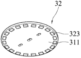
Or: said loading end is positive towards the one side of said lampshade, and the one side that deviates from said lampshade is the back side, and the said first light emitting diode group is installed in positive central region, and the said second light emitting diode group is installed in one week of edge at the back side.
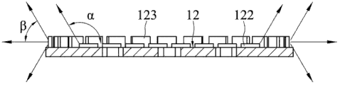
In the said first light emitting diode group, the positive irradiation angle of first light emitting diode is α, α with the loading end for the horizontal plane span be 0 the degree to 120 the degree; In the said second light emitting diode group, the side of second light emitting diode according to and back of the body irradiation angle β, β is that 0 degree is to 60 degree with the loading end for the horizontal plane span.
The said second light emitting diode group comprises a plurality of second light emitting diodes, and circular arc compartment of terrains such as said a plurality of second light emitting diodes are installed in one week of said edge.
Said radiating shell is coniform body, and the side wall surface of said radiating shell is uniformly-spaced installed vent rib.
Upper end outer rim one circle of said radiating shell is provided with lug boss.
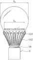
The diameter of said loading end is L
1, the maximum cross section diameter of said lampshade is L
2, L
1And L
2Satisfy following relational expression: 1/3L
1>L
2
The beneficial effect of the utility model mainly shows: increase irradiation angle range, illumination is more even.
Description of drawings
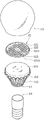
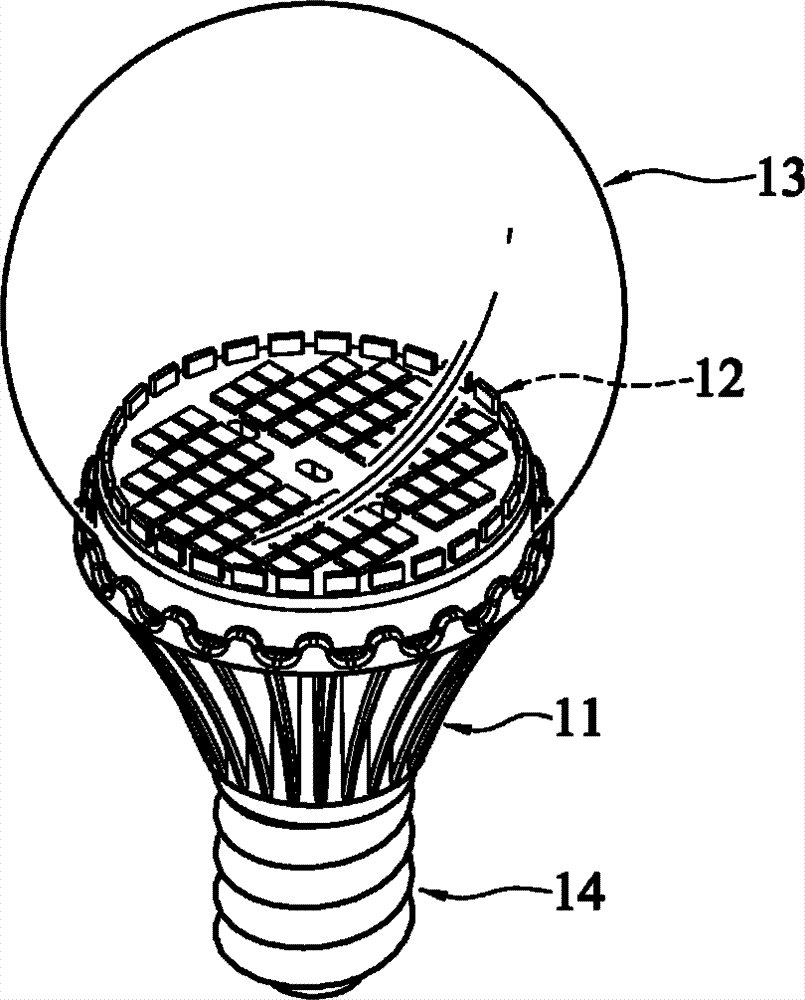
Fig. 1 is the exploded view of the wide area formula LED illumination bulb of embodiment 1;
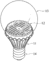
Fig. 2 is the structure chart of the wide area formula LED illumination bulb of embodiment 1;
Fig. 3 is the light path sketch map of the wide area formula LED illumination bulb of embodiment 1;
Fig. 4 is the plane of the wide area formula LED illumination bulb of embodiment 1;
Fig. 5 is the radiation response sketch map of the wide area formula LED illumination bulb of embodiment 1;
Fig. 6 is the exploded view of the wide area formula LED illumination bulb of embodiment 2;
Fig. 7 is the back of circuit board sketch map of the wide area formula LED illumination bulb of embodiment 2;
Fig. 8 is the radiation response sketch map of the wide area formula LED illumination bulb of embodiment 2.
The specific embodiment
Below in conjunction with accompanying drawing the utility model is further described.
With reference to Fig. 1~Fig. 8, a kind of wide area formula LED illumination bulb comprises a radiating shell 11, an illumination module 12, a lampshade 13 and an electrical connection section 14.
Wherein, said radiating shell 11 can dispel the heat ceramic made, and is a cone shape.Said radiating shell 11 has a pedestal 111, a plurality of vent rib 112 and a plurality of lug boss 113.
Stretch to the outer 111 upper surfaces by said radiating shell 11 of said pedestal.
112 of said vent ribs are formed on the side wall surface of said radiating shell 11, and said vent rib 112 is to be brought together towards the other end along stretching by the end face that said pedestal 111 is set.Said vent rib 112 is to supply heat conduction to use, so that thermal source is dissipated in the air by vent rib 112 convection current.
113 of said lug bosses are provided with the end face lateral margin place projection setting at interval of said pedestal 111 by said radiating shell 11, and are a wave-like.
12 of said illumination module comprise a circuit board 121, a plurality of first light emitting diode 122 and a plurality of second light emitting diode 123.
Said circuit board 121 is located at one of said pedestal side, and has a loading end, and the diameter that said loading end is set is L
2Said loading end comprises central region 1211 and one week 1212 of edge.
Said first light emitting diode 122 can surface mount technology, and (Surface mount technology SMT) is arranged at intervals on the central region 1211 of loading end of said circuit board 121.And can provide said wide area formula light emitting diode bulb 1 forward according to the angle.
Said second light emitting diode 123 can surface mount technology (Surface mount technology, the edge that SMT) is arranged at intervals at said circuit board 121 loading ends is on one week 1212, with said first light emitting diode 122 around wherein.Said second light emitting diode 123 can provide said wide area formula light emitting diode bulb 1 side direction according to the angle and dorsad according to the angle.
Said lampshade 13 can be made by transparent glass or plastic cement, and cover at one of said radiating shell 11 side.Wherein, the diameter of the cross section of said lampshade 13 the widest part is L
1
14 opposite sides that are arranged at said radiating shell 11 of said electrical connection section, and be electrically connected to said circuit board 121.Said electrical connection section 14 is can supply to be inserted on the lamp socket 2, on turn-on power to circuit board 121, uses power supply and gives said first light emitting diode 122 and said second light emitting diode 123.
When said wide area formula LED illumination bulb 1 when using; Said first light emitting diode 122 is arranged on the central region 1211 of loading end of said circuit board 121; Said second light emitting diode 123 is arranged at one week of edge of said loading end; And said pedestal 111 can be reduced by the outside projection of one of said radiating shell 11 end face and covers the back light source; Therefore, the light source that is produced by said first light emitting diode 122 just can provide according to effect, the light source that is produced by said second light emitting diode 123 can provide side according to and the back of the body according to effect.Light source more can be uniformly distributed in the illumination place.
Wherein, in a preferred embodiment, the positive irradiation angle α of said first light emitting diode 122; Horizontal plane by said pedestal 111 is counted, and is about 0 degree to 120 degree, and the side of said second light emitting diode 123 is shone and back of the body irradiation angle β; Horizontal plane by said loading end is counted, and is about 0 degree to 60 degree.In addition, L
1With L
2Can satisfy 1/3L
1>L
2Relational expression.By this; Just can provide simultaneously according to, side according to and the back of the body light angle of shining, and become the lamp envelope design of a wide projectional angle, and more can uniform irradiation to commonly using the position that bulb can't shine; And have more the effect of uniformly light-emitting, supply the user to obtain the illuminating effect of more comfortable and nature.
Please with reference to the 6th figure, the 7th figure and the 8th figure, it is exploded view, back of circuit board sketch map and light path sketch map for this creation wide area formula LED illumination bulb second embodiment.Among the figure, said wide area formula LED illumination bulb 3 comprises a radiating shell 31, an illumination module 32, a lampshade 33 and an electrical connection section 34.32 of said illumination module comprise a circuit board 321, a plurality of first light emitting diode 322 and a plurality of second light emitting diode 323.
In the present embodiment, because the structure of said radiating shell 32, said lampshade 23 and said electrical connection section 34 is identical with first embodiment with shape, repeat no more at this.The difference of the present embodiment and first embodiment is that said second light emitting diode 323 more can surface mount technology (Surface mount technology; SMT) edge at the back side that is arranged at said circuit board 321 is on one week; And directly provide the back of the body according to effect, to save manufacturing cost.
In sum, the wide area formula LED illumination bulb of the utility model, its effect is to be subject to according to establishing angle compared to existing bulb only can provide the forward irradiating angle, the utility model can provide side according to and back of the body irradiation angle, and can strengthen range of exposures.