CN202493344U - Electronic control system of revolution speed of diesel engine - Google Patents
Electronic control system of revolution speed of diesel engine Download PDFInfo
- Publication number
- CN202493344U CN202493344U CN2012201202492U CN201220120249U CN202493344U CN 202493344 U CN202493344 U CN 202493344U CN 2012201202492 U CN2012201202492 U CN 2012201202492U CN 201220120249 U CN201220120249 U CN 201220120249U CN 202493344 U CN202493344 U CN 202493344U
- Authority
- CN
- China
- Prior art keywords
- tooth bar
- engine
- rack
- controller
- rack displacement
- Prior art date
- Legal status (The legal status is an assumption and is not a legal conclusion. Google has not performed a legal analysis and makes no representation as to the accuracy of the status listed.)
- Expired - Fee Related
Links
- 238000006073 displacement reaction Methods 0.000 claims abstract description 52
- 238000002347 injection Methods 0.000 claims abstract description 25
- 239000007924 injection Substances 0.000 claims abstract description 25
- 230000005540 biological transmission Effects 0.000 claims 1
- 238000011897 real-time detection Methods 0.000 claims 1
- 239000000446 fuel Substances 0.000 abstract description 24
- 238000002485 combustion reaction Methods 0.000 abstract description 4
- 239000000126 substance Substances 0.000 description 2
- 230000009286 beneficial effect Effects 0.000 description 1
- 238000010586 diagram Methods 0.000 description 1
- 238000000034 method Methods 0.000 description 1
- 238000005086 pumping Methods 0.000 description 1
- 239000002699 waste material Substances 0.000 description 1
Images

Landscapes
- Electrical Control Of Air Or Fuel Supplied To Internal-Combustion Engine (AREA)
Abstract
一种柴油发动机转速电控系统属于柴油发动机转速控制领域,该系统包括发动机电控单元、发动机转速控制器、齿条位置控制器、齿条位移执行器、齿条位移传感器和发动机转速传感器;发动机电控单元与齿条位置控制器相连,齿条位置控制器与齿条位移执行器相连,齿条位移执行器与齿条位移传感器相连,齿条位移传感器与齿条位置控制器相连,发动机转速传感器分别与发动机转速控制器、发动机主轴相连,发动机转速控制器与发动机电控单元相连。本实用新型采用位置闭环和转速闭环的双闭环结构,对喷油泵的齿条移动控制精确,提高汽缸内的柴油燃烧效率,节约燃料。
A diesel engine speed electronic control system belongs to the field of diesel engine speed control, the system includes an engine electronic control unit, an engine speed controller, a rack position controller, a rack displacement actuator, a rack displacement sensor and an engine speed sensor; The electronic control unit is connected to the rack position controller, the rack position controller is connected to the rack displacement actuator, the rack displacement actuator is connected to the rack displacement sensor, the rack displacement sensor is connected to the rack position controller, the engine speed The sensors are respectively connected with the engine speed controller and the engine main shaft, and the engine speed controller is connected with the engine electronic control unit. The utility model adopts a double-closed-loop structure of position closed-loop and rotational speed closed-loop, which can precisely control the movement of the rack of the fuel injection pump, improve the combustion efficiency of diesel in the cylinder, and save fuel.
Description
技术领域 technical field
本实用新型属于柴油发动机转速控制领域,涉及一种柴油发动机转速电控系统。The utility model belongs to the field of diesel engine speed control and relates to an electric control system for the speed of a diesel engine.
背景技术 Background technique
柴油发动机喷油泵体内的泵油元件由喷油泵、柱塞和套筒组成。喷油泵体的上部是吸油腔,吸油腔通过两个小进油孔与压油腔相连,位于柱塞之上的压油腔经由柱塞上的垂直槽与吸油腔相通。供油终点以及所供的油量随着油泵柱塞的移动而产生变化。当柱塞向上移动而盖过吸油腔的进油孔时,喷油泵即开始供油;当柱塞的斜坡形控制边缘与进油孔相遇时,供油便停止了。因此,每个柱塞位置所对应的喷油量同发动机扭矩有一定的比例关系,与螺旋线成一定角度的柱塞旋转到一定角度即对应一定的喷油量。而喷油泵内柱塞的旋转是通过齿条的移动实现的。The pumping components in the fuel injection pump body of a diesel engine are composed of a fuel injection pump, a plunger and a sleeve. The upper part of the fuel injection pump body is the oil suction chamber, which is connected with the oil pressure chamber through two small oil inlet holes, and the oil pressure chamber located above the plunger communicates with the oil suction chamber through the vertical groove on the plunger. The end point of oil supply and the amount of oil supplied change with the movement of the oil pump plunger. When the plunger moves upward to cover the oil inlet hole of the oil suction chamber, the fuel injection pump starts to supply oil; when the slope-shaped control edge of the plunger meets the oil inlet hole, the oil supply stops. Therefore, the fuel injection quantity corresponding to each plunger position has a certain proportional relationship with the engine torque, and the plunger at a certain angle with the helix rotates to a certain angle to correspond to a certain fuel injection quantity. The rotation of the plunger in the fuel injection pump is realized by the movement of the rack.
目前,由柴油发动机驱动的车辆经常出现尾气排放超标的情况,这往往是由于柴油发动机对其喷油泵的齿条移动控制不够精确造成的,这种控制的不精确还会导致汽缸内的柴油燃烧效率低下,造成燃料的浪费和燃烧不充分,排放的尾气中有害物质含量超标,对环境造成严重污染。At present, vehicles driven by diesel engines often have excessive exhaust emissions. This is often caused by the diesel engine's inaccurate control of the rack movement of its fuel injection pump. This inaccurate control will also lead to diesel combustion in the cylinder. The efficiency is low, resulting in waste of fuel and insufficient combustion, and the content of harmful substances in the exhaust gas exceeds the standard, causing serious pollution to the environment.
因此,提供一种对柴油发动机喷油泵齿条移动进行精确控制的电控系统势在必行。Therefore, it is imperative to provide an electronic control system that accurately controls the rack movement of the diesel engine fuel injection pump.
实用新型内容 Utility model content
为了解决现有柴油发动机电控系统无法对柴油发动机喷油泵齿条移动进行精确控制的技术问题,本实用新型提供了一种柴油发动机转速电控系统。In order to solve the technical problem that the existing diesel engine electronic control system cannot accurately control the movement of the fuel injection pump rack of the diesel engine, the utility model provides an electronic control system for the diesel engine speed.
本实用新型解决技术问题所采取的技术方案如下:The technical scheme that the utility model solves the technical problem that takes is as follows:
一种柴油发动机转速电控系统包括发动机电控单元、发动机转速控制器、齿条位置控制器、齿条位移执行器、齿条位移传感器和发动机转速传感器;A diesel engine speed electronic control system includes an engine electronic control unit, an engine speed controller, a rack position controller, a rack displacement actuator, a rack displacement sensor and an engine speed sensor;
发动机电控单元与齿条位置控制器相连,齿条位置控制器与齿条位移执行器相连,齿条位移执行器与齿条位移传感器相连,齿条位移传感器与齿条位置控制器相连,发动机转速传感器分别与发动机转速控制器、发动机主轴相连,发动机转速控制器与发动机电控单元相连;齿条位置控制器、齿条位移执行器、齿条位移传感器构成位置闭环;发动机转速传感器、发动机转速控制器、发动机电控单元、齿条位置控制器、齿条位移执行器、发动机主轴构成转速闭环;The engine electronic control unit is connected to the rack position controller, the rack position controller is connected to the rack displacement actuator, the rack displacement actuator is connected to the rack displacement sensor, the rack displacement sensor is connected to the rack position controller, and the engine The speed sensor is respectively connected with the engine speed controller and the engine main shaft, and the engine speed controller is connected with the engine electronic control unit; the rack position controller, the rack displacement actuator and the rack displacement sensor form a position closed loop; the engine speed sensor, the engine speed The controller, the engine electronic control unit, the rack position controller, the rack displacement actuator, and the engine main shaft form a speed closed loop;
齿条位置控制器依据其接收到的发动机电控单元传送的齿条目标位置数据对齿条位移执行器进行控制;The rack position controller controls the rack displacement actuator according to the rack target position data received from the engine electronic control unit;
齿条位移执行器驱动发动机喷油泵的齿条以齿条目标位置数据对应的位移极值点为边界做往复运动;The rack displacement actuator drives the rack of the engine fuel injection pump to reciprocate with the displacement extreme point corresponding to the target position data of the rack as the boundary;
齿条位移传感器实时检测齿条实际到达的边界位置,并将齿条实际到达的边界位置数据传送给齿条位置控制器;The rack displacement sensor detects the boundary position actually reached by the rack in real time, and transmits the boundary position data actually reached by the rack to the rack position controller;
齿条位置控制器将齿条位移传感器传来的齿条实际到达的边界位置数据与发动机电控单元传来的齿条目标位置数据做差,获得的位置数据差值经过位置闭环后得到喷油泵齿条目标边界位置的修正值,位置闭环依据齿条目标边界位置的修正值修正喷油泵齿条位置,进而修正发动机主轴的实际转速;The rack position controller makes a difference between the actual arrival boundary position data of the rack transmitted from the rack displacement sensor and the target position data of the rack transmitted from the engine electronic control unit. The correction value of the target boundary position of the rack, the position closed loop corrects the rack position of the fuel injection pump according to the correction value of the target boundary position of the rack, and then corrects the actual speed of the engine main shaft;
发动机转速传感器实时检测发动机主轴的实际转速,并将发动机主轴的实际转速数据传送给发动机转速控制器;The engine speed sensor detects the actual speed of the engine main shaft in real time, and transmits the actual speed data of the engine main shaft to the engine speed controller;
发动机转速控制器将发动机转速传感器传送的发动机主轴的实际转速数据与发动机电控单元传送的目标转速数据做差,获得的转速数据差值经过发动机电控单元转换为齿条目标位置修正数据,并将该齿条目标位置修正数据传送给齿条位置控制器;The engine speed controller makes a difference between the actual speed data of the engine main shaft transmitted by the engine speed sensor and the target speed data transmitted by the engine electronic control unit, and the obtained speed data difference is converted into rack target position correction data by the engine electronic control unit, and Send the rack target position correction data to the rack position controller;
齿条位置控制器将齿条位移传感器传来的齿条实际到达的边界位置数据与发动机电控单元传来的齿条目标位置修正数据做差,获得的位置数据差值经过位置闭环后得到喷油泵齿条目标边界位置的修正值,位置闭环依据齿条目标边界位置的修正值修正喷油泵齿条位置,进而修正发动机主轴的实际转速。The rack position controller makes a difference between the actual arrival boundary position data of the rack transmitted from the rack displacement sensor and the correction data of the rack target position transmitted from the engine electronic control unit, and the obtained position data difference is obtained after the position closed loop. The correction value of the target boundary position of the fuel pump rack, the position closed loop corrects the position of the fuel injection pump rack according to the correction value of the target boundary position of the rack, and then corrects the actual speed of the engine main shaft.
本实用新型的有益效果是:该系统采用双闭环结构,对喷油泵的齿条移动控制精确,提高汽缸内的柴油燃烧效率,节约燃料,进而减少柴油发动机尾气排放中的有害物质含量,降低对环境造成的污染。The beneficial effects of the utility model are: the system adopts a double-closed-loop structure, which can accurately control the rack movement of the fuel injection pump, improve the combustion efficiency of diesel in the cylinder, save fuel, and further reduce the content of harmful substances in the exhaust emission of diesel engines, reducing the impact on pollution caused by the environment.
附图说明 Description of drawings
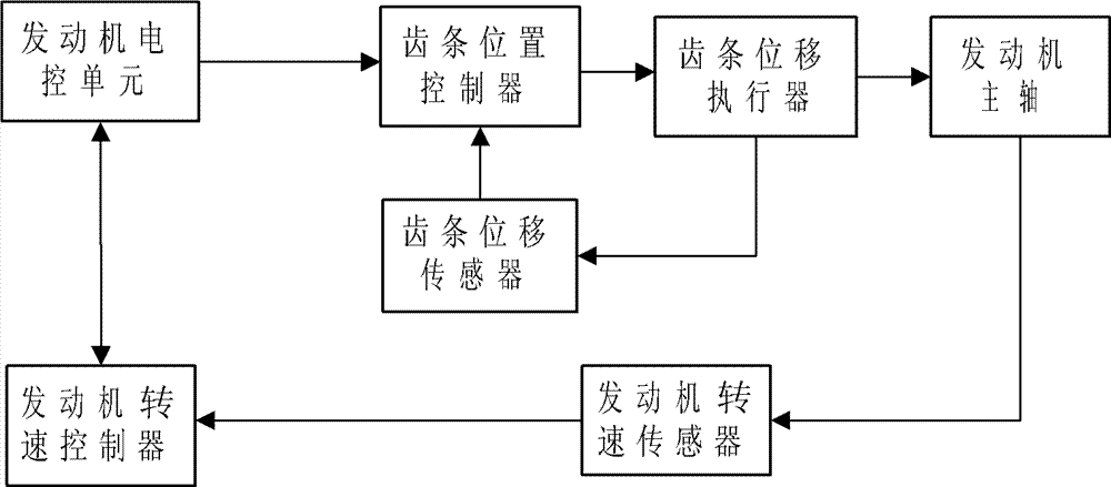
图1是本实用新型柴油发动机转速电控系统的结构框图。Fig. 1 is a structural block diagram of the electric control system for the rotational speed of the diesel engine of the present invention.
具体实施方式 Detailed ways
下面结合附图对本实用新型做进一步详细说明。Below in conjunction with accompanying drawing, the utility model is described in further detail.
如图1所示,本实用新型的柴油发动机转速电控系统由发动机电控单元、发动机转速控制器、齿条位置控制器、齿条位移执行器、齿条位移传感器、发动机转速传感器组成;发动机电控单元与齿条位置控制器相连,齿条位置控制器与齿条位移执行器相连,齿条位移执行器与齿条位移传感器相连,齿条位移传感器与齿条位置控制器相连,发动机转速传感器分别与发动机转速控制器、发动机主轴相连,发动机转速控制器与发动机电控单元相连;齿条位置控制器、齿条位移执行器、齿条位移传感器构成位置闭环;发动机转速传感器、发动机转速控制器、发动机电控单元、齿条位置控制器、齿条位移执行器、发动机主轴构成转速闭环。As shown in Figure 1, the diesel engine speed electronic control system of the utility model is composed of an engine electronic control unit, an engine speed controller, a rack position controller, a rack displacement actuator, a rack displacement sensor, and an engine speed sensor; The electronic control unit is connected to the rack position controller, the rack position controller is connected to the rack displacement actuator, the rack displacement actuator is connected to the rack displacement sensor, the rack displacement sensor is connected to the rack position controller, the engine speed The sensors are respectively connected with the engine speed controller and the engine main shaft, and the engine speed controller is connected with the engine electronic control unit; the rack position controller, the rack displacement actuator and the rack displacement sensor form a position closed loop; the engine speed sensor, the engine speed control The controller, the engine electronic control unit, the rack position controller, the rack displacement actuator, and the engine spindle form a closed loop of speed.
本实用新型的柴油发动机转速电控系统的工作原理是:齿条位置控制器依据发动机电控单元传送的齿条目标位置数据对齿条位移执行器进行控制;齿条位移执行器驱动发动机喷油泵的齿条做往复运动;齿条位移传感器实时将齿条的边界位置数据传送给齿条位置控制器;齿条位置控制器通过位置闭环修正喷油泵齿条位置,进而修正发动机主轴的实际转速;发动机转速传感器实时将发动机主轴的实际转速数据传送给发动机转速控制器;发动机转速控制器通过转速闭环修正发动机主轴的实际转速。The working principle of the diesel engine rotational speed electric control system of the utility model is: the rack position controller controls the rack displacement actuator according to the rack target position data transmitted by the engine electronic control unit; the rack displacement actuator drives the engine fuel injection pump The rack does reciprocating motion; the rack displacement sensor transmits the boundary position data of the rack to the rack position controller in real time; the rack position controller corrects the rack position of the fuel injection pump through the position closed loop, and then corrects the actual speed of the engine spindle; The engine speed sensor transmits the actual speed data of the engine main shaft to the engine speed controller in real time; the engine speed controller corrects the actual speed of the engine main shaft through the speed closed loop.
本实用新型以德国的BOSCH直列式喷油泵和6DE2柴油机为对象,完成喷油泵齿条位移和发动机转速的控制实验。其中,发动机电控单元采用Winbond(华邦)公司的W77E58单片机;齿条位移执行采用德国BOSCH公司的电磁执行器,该电磁执行器由PWM波(脉宽调制信号)进行驱动,PWM波的频率变化范围在150Hz-250Hz之间;齿条位移传感器采用德国BOSCH公司电控喷油泵产品中的位移传感器;齿条行程为0~20毫米,齿条位置控制器对齿条位置的控制精度≤0.04毫米。The utility model takes the German BOSCH in-line fuel injection pump and 6DE2 diesel engine as objects, and completes the control experiment of the rack displacement of the fuel injection pump and the engine speed. Among them, the engine electronic control unit adopts the W77E58 single-chip microcomputer of Winbond (Winbond) company; the rack displacement execution adopts the electromagnetic actuator of the German BOSCH company, and the electromagnetic actuator is driven by PWM wave (pulse width modulation signal), and the frequency of PWM wave The change range is between 150Hz-250Hz; the rack displacement sensor adopts the displacement sensor in the electric control fuel injection pump product of BOSCH company in Germany; the stroke of the rack is 0-20 mm, and the control accuracy of the rack position controller to the rack position is ≤0.04 mm.
Claims (1)
Priority Applications (1)
| Application Number | Priority Date | Filing Date | Title |
|---|---|---|---|
| CN2012201202492U CN202493344U (en) | 2012-03-27 | 2012-03-27 | Electronic control system of revolution speed of diesel engine |
Applications Claiming Priority (1)
| Application Number | Priority Date | Filing Date | Title |
|---|---|---|---|
| CN2012201202492U CN202493344U (en) | 2012-03-27 | 2012-03-27 | Electronic control system of revolution speed of diesel engine |
Publications (1)
| Publication Number | Publication Date |
|---|---|
| CN202493344U true CN202493344U (en) | 2012-10-17 |
Family
ID=46999576
Family Applications (1)
| Application Number | Title | Priority Date | Filing Date |
|---|---|---|---|
| CN2012201202492U Expired - Fee Related CN202493344U (en) | 2012-03-27 | 2012-03-27 | Electronic control system of revolution speed of diesel engine |
Country Status (1)
| Country | Link |
|---|---|
| CN (1) | CN202493344U (en) |
Cited By (3)
| Publication number | Priority date | Publication date | Assignee | Title |
|---|---|---|---|---|
| CN102913335A (en) * | 2012-10-26 | 2013-02-06 | 中国北车集团大连机车车辆有限公司 | Method and device for controlling natural gas electrospray of high-power diesel engine |
| CN104847510A (en) * | 2015-03-23 | 2015-08-19 | 柳州柳工挖掘机有限公司 | Automatic engineering mechanical engine rotation speed drift compensation method |
| CN111102082A (en) * | 2019-12-30 | 2020-05-05 | 三一重机有限公司 | Accelerator control device, control method thereof and excavator |
-
2012
- 2012-03-27 CN CN2012201202492U patent/CN202493344U/en not_active Expired - Fee Related
Cited By (6)
| Publication number | Priority date | Publication date | Assignee | Title |
|---|---|---|---|---|
| CN102913335A (en) * | 2012-10-26 | 2013-02-06 | 中国北车集团大连机车车辆有限公司 | Method and device for controlling natural gas electrospray of high-power diesel engine |
| CN102913335B (en) * | 2012-10-26 | 2015-03-25 | 中国北车集团大连机车车辆有限公司 | Method and device for controlling natural gas electrospray of high-power diesel engine |
| CN104847510A (en) * | 2015-03-23 | 2015-08-19 | 柳州柳工挖掘机有限公司 | Automatic engineering mechanical engine rotation speed drift compensation method |
| CN104847510B (en) * | 2015-03-23 | 2017-11-24 | 柳州柳工挖掘机有限公司 | Engineering machinery engine rotating speed drift automatic compensating method |
| CN111102082A (en) * | 2019-12-30 | 2020-05-05 | 三一重机有限公司 | Accelerator control device, control method thereof and excavator |
| CN111102082B (en) * | 2019-12-30 | 2022-07-29 | 三一重机有限公司 | Accelerator control device, control method thereof and excavator |
Similar Documents
| Publication | Publication Date | Title |
|---|---|---|
| CN101440765B (en) | Control method of a direct injection system of the common rail type provided with a high-pressure fuel pump | |
| RU2360139C2 (en) | Controller of internal combustion engine | |
| CN202493344U (en) | Electronic control system of revolution speed of diesel engine | |
| CN104791211B (en) | Electromagnetic type variable cam mechanism and little pulsation variable-flow fueller | |
| CN102562341A (en) | Engine control unit | |
| CN100549393C (en) | Internal combustion engine idle speed controller and internal combustion engine | |
| CN102562337A (en) | Controller for high-pressure oil pump of gasoline direct-injection engine based on volume of fuel oil | |
| CN102506001B (en) | A kind of injection characteristics scaling method based on electronically controlled unit pump pretravel | |
| CN204716409U (en) | Marine high-pressure common rail diesel engine automatical control system | |
| RU2009115665A (en) | ELECTRONIC ENGINE CONTROL SYSTEM FOR PISTON PUMP | |
| CN104265473B (en) | The energy-saving control system and engineering machinery of a kind of engine | |
| CN105240177A (en) | Diesel engine fuel oil injection electrically-controlled unit combination pump for non-road mobile machinery | |
| CN113958382A (en) | Low-speed diesel engine electronic cylinder oiling control system | |
| CN105569863B (en) | Engine fuel injection control method and engine electric-controlled unit | |
| CN101922391B (en) | Fuel jet electronic combination unit pump of diesel engine | |
| CN102383956B (en) | Air inlet electric control spraying two-stroke kerosene engine | |
| CN1200436A (en) | Engine controls for construction machinery | |
| CN2606486Y (en) | A Magneto Motor Rotor for EFI Motorcycle | |
| CN204591609U (en) | Electromagnetic type variable cam mechanism and little pulsation variable-flow oil supplying device | |
| CN203201670U (en) | System for hydraulic compression control of homogenized mixed gas combustion of internal combustion engine | |
| CN103775322B (en) | Sensory feedback programmable servo volume adjustable hydraulic pump | |
| CN105781769A (en) | Device and method for low pumping losses of gasoline rotor machine through interval oil injection | |
| CN202187830U (en) | Two-stroke kerosene engine with air inlet flue capable of electronically-controlled injection | |
| CN202926473U (en) | Diesel engine electric control speed regulating device based on single chip microcomputer | |
| CN205154396U (en) | Novel internal -combustion engine transmission device |
Legal Events
| Date | Code | Title | Description |
|---|---|---|---|
| C14 | Grant of patent or utility model | ||
| GR01 | Patent grant | ||
| C17 | Cessation of patent right | ||
| CF01 | Termination of patent right due to non-payment of annual fee |
Granted publication date: 20121017 Termination date: 20130327 |