CN202492864U - Drive control system of prefabricated pile experimental centrifuge - Google Patents
Drive control system of prefabricated pile experimental centrifuge Download PDFInfo
- Publication number
- CN202492864U CN202492864U CN2012200893900U CN201220089390U CN202492864U CN 202492864 U CN202492864 U CN 202492864U CN 2012200893900 U CN2012200893900 U CN 2012200893900U CN 201220089390 U CN201220089390 U CN 201220089390U CN 202492864 U CN202492864 U CN 202492864U
- Authority
- CN
- China
- Prior art keywords
- programmable logic
- logic controller
- frequency converter
- model
- utility
- Prior art date
- Legal status (The legal status is an assumption and is not a legal conclusion. Google has not performed a legal analysis and makes no representation as to the accuracy of the status listed.)
- Expired - Fee Related
Links
- 238000002474 experimental method Methods 0.000 claims description 5
- 230000009286 beneficial effect Effects 0.000 abstract description 2
- 238000004519 manufacturing process Methods 0.000 abstract description 2
- 239000004567 concrete Substances 0.000 description 6
- 238000000034 method Methods 0.000 description 5
- 238000010586 diagram Methods 0.000 description 3
- 235000017166 Bambusa arundinacea Nutrition 0.000 description 1
- 235000017491 Bambusa tulda Nutrition 0.000 description 1
- 241001330002 Bambuseae Species 0.000 description 1
- 235000015334 Phyllostachys viridis Nutrition 0.000 description 1
- 229910000831 Steel Inorganic materials 0.000 description 1
- 239000011425 bamboo Substances 0.000 description 1
- 239000004568 cement Substances 0.000 description 1
- 238000010276 construction Methods 0.000 description 1
- 230000007547 defect Effects 0.000 description 1
- 230000000694 effects Effects 0.000 description 1
- 238000009776 industrial production Methods 0.000 description 1
- 230000004048 modification Effects 0.000 description 1
- 238000012986 modification Methods 0.000 description 1
- 238000000465 moulding Methods 0.000 description 1
- 239000011513 prestressed concrete Substances 0.000 description 1
- 239000010959 steel Substances 0.000 description 1
Images


Classifications
-
- Y—GENERAL TAGGING OF NEW TECHNOLOGICAL DEVELOPMENTS; GENERAL TAGGING OF CROSS-SECTIONAL TECHNOLOGIES SPANNING OVER SEVERAL SECTIONS OF THE IPC; TECHNICAL SUBJECTS COVERED BY FORMER USPC CROSS-REFERENCE ART COLLECTIONS [XRACs] AND DIGESTS
- Y02—TECHNOLOGIES OR APPLICATIONS FOR MITIGATION OR ADAPTATION AGAINST CLIMATE CHANGE
- Y02P—CLIMATE CHANGE MITIGATION TECHNOLOGIES IN THE PRODUCTION OR PROCESSING OF GOODS
- Y02P90/00—Enabling technologies with a potential contribution to greenhouse gas [GHG] emissions mitigation
- Y02P90/02—Total factory control, e.g. smart factories, flexible manufacturing systems [FMS] or integrated manufacturing systems [IMS]
Landscapes
- Centrifugal Separators (AREA)
Abstract
本实用新型公开了预制桩实验型离心机驱动控制系统,其特征在于,包括速度传感器、可编程逻辑控制器、变频器和人机界面,所述速度传感器安装于离心机管模的外部,速度传感器的信号由可编程逻辑控制器的输入端接收,人机界面上位控制可编程逻辑控制器,可编程逻辑控制器的输出端连接变频器,变频器的另一端连接有电机。本实用新型的有益效果在于:可以实现精确的工艺要求,参数调整方便,人机界面更人性化,从而提高劳动效率,为自动化生产提供保障。
The utility model discloses a drive control system for a prefabricated pile experimental centrifuge, which is characterized in that it includes a speed sensor, a programmable logic controller, a frequency converter and a man-machine interface, the speed sensor is installed outside the pipe mold of the centrifuge, and the speed The signal of the sensor is received by the input terminal of the programmable logic controller, the human-machine interface host controls the programmable logic controller, the output terminal of the programmable logic controller is connected to the frequency converter, and the other end of the frequency converter is connected to the motor. The beneficial effect of the utility model is that: accurate technological requirements can be realized, parameter adjustment is convenient, and the human-machine interface is more humanized, thereby improving labor efficiency and providing guarantee for automatic production.
Description
技术领域 technical field
本实用新型涉及混凝土实验型预制桩设备技术领域,特别是预应力混凝土管桩实验型离心机的驱动控制。The utility model relates to the technical field of concrete experimental prefabricated pile equipment, in particular to the driving control of a prestressed concrete pipe pile experimental centrifuge.
背景技术 Background technique
作为建筑领域的离心混凝土制品在市场上较多,如有管桩、电杆、方桩、竹节桩和带肋桩等。它们都是通过离心式模具在离心机上高速旋转,使模具中的混凝土作高速离心运动,制作成混凝土制品。离心工艺十分成熟,都已经进入大规模工业化生产,但实验型离心机目前还是一片空白,如前期水泥制品工业用离心成型机技术条件(JC/T822-2003)等国家规范对混凝土离心工艺的基本性能做了明确规定。为了制作出符合要求的预制桩,需要前期大量的实验来完成。然而,在实际实验中,实验型离心机的转速由于钢模磨损、电压、其它部件的损耗等,都将影响实验数据,此类原因将会使得预制桩的实验变的不稳定。There are many centrifugal concrete products in the construction field, such as pipe piles, poles, square piles, bamboo piles and ribbed piles. They all rotate at a high speed on a centrifuge through a centrifugal mold, so that the concrete in the mold is centrifugally moved at a high speed to make concrete products. The centrifuge process is very mature and has entered large-scale industrial production, but the experimental centrifuge is still a blank, such as the technical conditions of the centrifugal molding machine for the cement product industry (JC/T822-2003) and other national standards for the basic centrifuge process of concrete. Performance is clearly defined. In order to make prefabricated piles that meet the requirements, a lot of experiments in the early stage are required to complete. However, in the actual experiment, the speed of the experimental centrifuge will affect the experimental data due to the wear of the steel mold, the loss of voltage, and other components. Such reasons will make the experiment of the prefabricated pile unstable.
综上所述,针对现有技术的缺陷,特别需要一种预制桩实验型离心机驱动控制系统,以解决以上提到的问题。To sum up, in view of the defects of the prior art, there is a special need for a prefabricated pile experimental centrifuge drive control system to solve the above-mentioned problems.
实用新型内容 Utility model content
本实用新型所要解决的技术问题在于,克服现有技术中存在的理论转速与实际转速不符,参数调整不方便的问题,提供一种精度高的、自动校准的预制桩实验型离心机驱动控制系统。The technical problem to be solved by the utility model is to overcome the problems existing in the prior art that the theoretical rotation speed does not match the actual rotation speed and the problem of inconvenient parameter adjustment, and provide a high-precision, automatic calibration prefabricated pile experimental centrifuge drive control system .
本实用新型所解决的技术问题可以采用以下技术方案来实现:The technical problem solved by the utility model can be realized by adopting the following technical solutions:
预制桩实验型离心机驱动控制系统,其特征在于,包括速度传感器、可编程逻辑控制器、变频器和人机界面,所述速度传感器安装于离心机管模的外部,速度传感器的信号由可编程逻辑控制器的输入端接收,人机界面上位控制可编程逻辑控制器,可编程逻辑控制器的输出端连接变频器,变频器的另一端连接有电机。The prefabricated pile experimental type centrifuge drive control system is characterized in that it includes a speed sensor, a programmable logic controller, a frequency converter and a man-machine interface. The speed sensor is installed outside the centrifuge pipe mold, and the signal of the speed sensor can be controlled by The input terminal of the programmable logic controller is received, the human-machine interface host controls the programmable logic controller, the output terminal of the programmable logic controller is connected to the frequency converter, and the other end of the frequency converter is connected to the motor.
在本实用新型的一个实施例中,所述变频器采用RS-485接口。In one embodiment of the present utility model, the frequency converter adopts RS-485 interface.
本实用新型的有益效果在于:可以实现精确的工艺要求,参数调整方便,人机界面更人性化,从而提高劳动效率,为自动化生产提供保障。The beneficial effect of the utility model is that: accurate technological requirements can be realized, parameter adjustment is convenient, and the human-machine interface is more humanized, thereby improving labor efficiency and providing guarantee for automatic production.
附图说明 Description of drawings
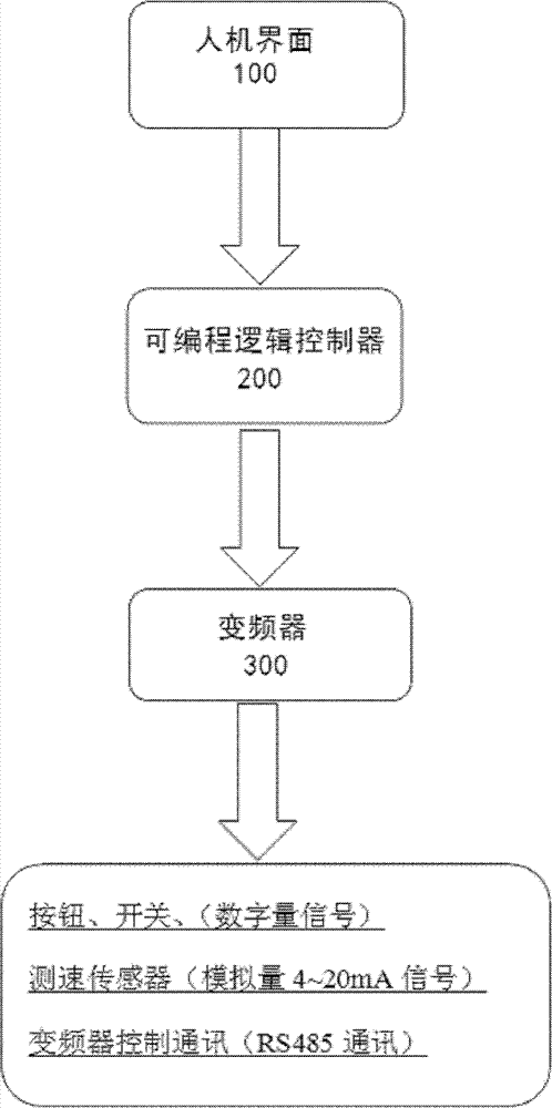
图1为本实用新型所述的控制系统的框架图。Fig. 1 is a frame diagram of the control system described in the utility model.
图2为本实用新型所述的人机界面示意图。Fig. 2 is a schematic diagram of the man-machine interface described in the present invention.
图3为本实用新型所述的PLC程序示意图。Fig. 3 is a schematic diagram of the PLC program described in the utility model.
具体实施方式 Detailed ways
为使本实用新型实现的技术手段、创作特征、达成目的与功效易于明白了解,下面结合具体实施方式,进一步阐述本实用新型。In order to make the technical means, creative features, goals and effects achieved by the utility model easy to understand, the utility model will be further elaborated below in conjunction with specific embodiments.
如图1所示,本实用新型所述的预制桩实验型离心机驱动控制系统,其特征在于,包括速度传感器、可编程逻辑控制器、变频器和人机界面,所述速度传感器安装于离心机管模的外部,速度传感器的信号由可编程逻辑控制器的输入端接收,人机界面上位控制可编程逻辑控制器,可编程逻辑控制器的输出端连接变频器,变频器的另一端连接有电机;所述变频器采用RS-485接口。As shown in Fig. 1, the drive control system of the prefabricated pile experimental centrifuge described in the utility model is characterized in that it includes a speed sensor, a programmable logic controller, a frequency converter and a man-machine interface, and the speed sensor is installed in the centrifuge Outside the machine tube mold, the signal of the speed sensor is received by the input terminal of the programmable logic controller. There is a motor; the frequency converter adopts RS-485 interface.
所述人机界面如图2所示,人机界面程序五参数修改和运行界面,可以修改运转速度和时间。The man-machine interface is shown in Figure 2, the man-machine interface program five parameter modification and operation interface, can modify the operating speed and time.
如图3所示,本实用新型的工作流程如下:首先,PLC读出设置转速,发指令给变频器驱动电机,测速传感器(X0,X1)检测实际速度,如果实际速度超过或低于理论速度的2%,通过测速传感器将信号传送给PLC,PLC内部程序通过PID运算,实时自动修正电机转速;反之,PID将不工作,程序正常运转,使电机转速在工艺要求内。As shown in Figure 3, the working process of the utility model is as follows: first, the PLC reads the set speed, sends instructions to the frequency converter to drive the motor, and the speed sensor (X0, X1) detects the actual speed, if the actual speed exceeds or is lower than the theoretical speed 2%, the signal is transmitted to the PLC through the speed sensor, and the internal program of the PLC automatically corrects the motor speed in real time through the PID operation; otherwise, the PID will not work, and the program will run normally to make the motor speed within the process requirements.
本实用新型涉及混凝土实验型预制桩,参数调整方便,转速运转可控,实验数据精确。降低了管模实际转速与理论转速的差异,保障产品的稳定性。The utility model relates to a concrete experimental prefabricated pile, which has the advantages of convenient parameter adjustment, controllable rotating speed and accurate experimental data. The difference between the actual speed of the pipe mold and the theoretical speed is reduced, and the stability of the product is guaranteed.
以上显示和描述了本实用新型的基本原理和主要特征和本实用新型的优点。本行业的技术人员应该了解,本实用新型不受上述实施例的限制,上述实施例和说明书中描述的只是说明本实用新型的原理,在不脱离本实用新型精神和范围的前提下,本实用新型还会有各种变化和改进,这些变化和改进都落入要求保护的本实用新型范围内。本实用新型要求保护范围由所附的权利要求书及其等效物界定。The basic principles and main features of the present utility model and the advantages of the present utility model have been shown and described above. Those skilled in the industry should understand that the utility model is not limited by the above-mentioned embodiments. The above-mentioned embodiments and descriptions only illustrate the principle of the utility model. Without departing from the spirit and scope of the utility model, the utility model The new model also has various changes and improvements, and these changes and improvements all fall within the scope of the claimed utility model. The scope of protection required by the utility model is defined by the appended claims and their equivalents.
Claims (2)
Priority Applications (1)
| Application Number | Priority Date | Filing Date | Title |
|---|---|---|---|
| CN2012200893900U CN202492864U (en) | 2012-03-09 | 2012-03-09 | Drive control system of prefabricated pile experimental centrifuge |
Applications Claiming Priority (1)
| Application Number | Priority Date | Filing Date | Title |
|---|---|---|---|
| CN2012200893900U CN202492864U (en) | 2012-03-09 | 2012-03-09 | Drive control system of prefabricated pile experimental centrifuge |
Publications (1)
| Publication Number | Publication Date |
|---|---|
| CN202492864U true CN202492864U (en) | 2012-10-17 |
Family
ID=46999099
Family Applications (1)
| Application Number | Title | Priority Date | Filing Date |
|---|---|---|---|
| CN2012200893900U Expired - Fee Related CN202492864U (en) | 2012-03-09 | 2012-03-09 | Drive control system of prefabricated pile experimental centrifuge |
Country Status (1)
| Country | Link |
|---|---|
| CN (1) | CN202492864U (en) |
-
2012
- 2012-03-09 CN CN2012200893900U patent/CN202492864U/en not_active Expired - Fee Related
Similar Documents
| Publication | Publication Date | Title |
|---|---|---|
| CN103301927B (en) | Automatic control system of road stone crusher | |
| CN205485598U (en) | Large -scale electric machine coil coiling machine control system | |
| CN204820234U (en) | Injection molding machine of sucking disc manipulator is rotated in area | |
| CN201473634U (en) | Device for reducing waste silk in semi-automatic spinning line | |
| CN201410556Y (en) | Full-automatic control device for cast iron pipe production equipment | |
| CN104295543B (en) | Hybrid power engineering machinery composite move control method | |
| CN202492864U (en) | Drive control system of prefabricated pile experimental centrifuge | |
| CN203635643U (en) | Full automatic wire drawing machine control system | |
| CN102502410B (en) | Quick following control method for lifting motor and opening and closing motor of grabbing crane | |
| CN202120083U (en) | Integrated control system of centrifugal casting machine | |
| CN202894310U (en) | Automatic pouring machine for achieving equipressure and equal quantity of sector ladle and liquid iron through parameter control of tilting angle and cutting angle | |
| CN202984624U (en) | Control device of roller type centrifugal casting machine | |
| CN204056442U (en) | A kind of multi-functional three servo wrapping machine control setups | |
| CN206999370U (en) | A kind of dust-proof feeding inlet structure of ABS products feed paddle device | |
| CN202468392U (en) | Blower fan switching control system for roller kiln | |
| CN104480579A (en) | Method for realizing spindle speed curve of spinning machine spindle yarn winding | |
| CN202805721U (en) | Control system for vertical type numerical control spinning machine | |
| CN104943232A (en) | Automatic adjustment and control system for mold closing height of fine blanking machine and control method thereof | |
| CN205874226U (en) | High -speed coating feed system for wire drawing | |
| CN203012536U (en) | Automatic-control PH neutralization device | |
| CN204904055U (en) | Caragana microphylla granulation machine intelligent control device | |
| CN202480371U (en) | Device for automatically controlling thickness and gram weight of film from blown film machine | |
| CN204360172U (en) | Large-scale automatic centrifugation ore separators PLC control system | |
| CN203191765U (en) | Automatic Control System of Pipe Making Machine | |
| CN201792465U (en) | Energy-saving control system for injection molding machine |
Legal Events
| Date | Code | Title | Description |
|---|---|---|---|
| C14 | Grant of patent or utility model | ||
| GR01 | Patent grant | ||
| CF01 | Termination of patent right due to non-payment of annual fee |
Granted publication date: 20121017 Termination date: 20160309 |
|
| CF01 | Termination of patent right due to non-payment of annual fee |