CN202492796U - Intelligent dynamometric support for bridge health - Google Patents
Intelligent dynamometric support for bridge health Download PDFInfo
- Publication number
- CN202492796U CN202492796U CN201220019408XU CN201220019408U CN202492796U CN 202492796 U CN202492796 U CN 202492796U CN 201220019408X U CN201220019408X U CN 201220019408XU CN 201220019408 U CN201220019408 U CN 201220019408U CN 202492796 U CN202492796 U CN 202492796U
- Authority
- CN
- China
- Prior art keywords
- optical fiber
- force
- support
- plate
- measuring
- Prior art date
- Legal status (The legal status is an assumption and is not a legal conclusion. Google has not performed a legal analysis and makes no representation as to the accuracy of the status listed.)
- Expired - Fee Related
Links
- 239000013307 optical fiber Substances 0.000 claims abstract description 69
- 230000003287 optical effect Effects 0.000 claims abstract description 7
- 239000000835 fiber Substances 0.000 claims description 6
- 239000011521 glass Substances 0.000 claims description 6
- 229920000271 Kevlar® Polymers 0.000 claims description 5
- 229910000831 Steel Inorganic materials 0.000 claims description 5
- 239000004761 kevlar Substances 0.000 claims description 5
- 239000010959 steel Substances 0.000 claims description 5
- 230000001939 inductive effect Effects 0.000 claims 1
- 238000012544 monitoring process Methods 0.000 abstract description 14
- 238000005259 measurement Methods 0.000 abstract description 2
- 230000002159 abnormal effect Effects 0.000 abstract 1
- 238000000034 method Methods 0.000 description 4
- 238000001514 detection method Methods 0.000 description 3
- 238000010586 diagram Methods 0.000 description 3
- 238000005516 engineering process Methods 0.000 description 3
- 230000003862 health status Effects 0.000 description 3
- 230000007774 longterm Effects 0.000 description 3
- 238000012360 testing method Methods 0.000 description 3
- XAGFODPZIPBFFR-UHFFFAOYSA-N aluminium Chemical compound [Al] XAGFODPZIPBFFR-UHFFFAOYSA-N 0.000 description 2
- 229910052782 aluminium Inorganic materials 0.000 description 2
- 238000004364 calculation method Methods 0.000 description 2
- 238000007689 inspection Methods 0.000 description 2
- 238000009434 installation Methods 0.000 description 2
- 238000004458 analytical method Methods 0.000 description 1
- 238000010276 construction Methods 0.000 description 1
- 238000013480 data collection Methods 0.000 description 1
- 230000007812 deficiency Effects 0.000 description 1
- 229920006335 epoxy glue Polymers 0.000 description 1
- 238000002474 experimental method Methods 0.000 description 1
- 238000012423 maintenance Methods 0.000 description 1
- 238000000691 measurement method Methods 0.000 description 1
- 238000012986 modification Methods 0.000 description 1
- 230000004048 modification Effects 0.000 description 1
- 238000011179 visual inspection Methods 0.000 description 1
Images


Landscapes
- Force Measurement Appropriate To Specific Purposes (AREA)
Abstract
本实用新型涉及一种桥梁健康的智能测力支座,包括板式橡胶支座,其特征在于:所述板式橡胶支座安装有测力元件,所述测力元件包括多个用于感应支座的轴压力和剪切力且对称设置在板式橡胶支座内的光纤应变传感器,所述光纤应变传感器均连接到将光信号转换成电信号并以应变的形式显示出来的光纤数据采集转换器,并取光纤数据采集转换器采集的多个光纤应变传感器读数的平均值作为最终的支座受力应变测量值。本实用新型能准确、有效地监测桥梁支座的受力情况,且该支座外形上无异于普通支座,其制作和安装方便,可以用来对桥梁的施工荷载、车辆超载和桥梁性能的异常变化进行实时跟踪和监测。
The utility model relates to an intelligent force-measuring support for bridge health, which includes a plate-type rubber support, and is characterized in that: the plate-type rubber support is equipped with a force-measuring element, and the force-measuring element includes a plurality of The axial pressure and shear force are symmetrically arranged in the optical fiber strain sensor in the plate rubber bearing, and the optical fiber strain sensor is connected to the optical fiber data acquisition converter that converts the optical signal into an electrical signal and displays it in the form of strain, And the average value of the readings of multiple optical fiber strain sensors collected by the optical fiber data acquisition converter is taken as the final force and strain measurement value of the support. The utility model can accurately and effectively monitor the stress situation of the bridge support, and the shape of the support is no different from that of the ordinary support. Real-time tracking and monitoring of abnormal changes.
Description
技术领域 technical field
本实用新型涉及一种桥梁健康监测的智能测力支座,适用于监测桥梁及其它工程结构。 The utility model relates to an intelligent force-measuring bearing for bridge health monitoring, which is suitable for monitoring bridges and other engineering structures. the
背景技术 Background technique
一直以来,桥梁支座的监测主要是通过传统的手工和目测的方法进行的,例如借助望远镜等简单工具进行检查,一般必须到桥下登梯或使用高花费的桥梁监测车进行检测。由于墩台较高,而且梁、板与墩台之间的净空很小,检测工作不仅非常不便,而且具有一定的危险性。最主要的是这种检测方法无法确定支座的实际工作性能,也无法监测支座的受力情况乃至桥梁结构的健康状况。 For a long time, the monitoring of bridge bearings has been mainly carried out through traditional manual and visual inspection methods, such as inspections with the help of simple tools such as telescopes. Generally, it is necessary to go to the bridge under the bridge or use a high-cost bridge monitoring vehicle for inspection. Due to the high pier abutment and the small clearance between beams, slabs and pier abutment, the detection work is not only very inconvenient, but also has certain dangers. The most important thing is that this detection method cannot determine the actual working performance of the bearing, nor can it monitor the stress situation of the bearing or even the health status of the bridge structure. the
发明内容 Contents of the invention
鉴于现有技术的不足,本实用新型的目的在于提供一种能准确、有效地检测桥梁健康状况的智能测力支座。 In view of the deficiencies in the prior art, the purpose of this utility model is to provide an intelligent force-measuring bearing that can accurately and effectively detect the health status of a bridge. the
为了实现上述目的,本实用新型的技术方案是:一种桥梁健康的智能测力支座,包括板式橡胶支座,其特征在于:所述板式橡胶支座安装有测力元件,所述测力元件包括多个用于感应支座的轴压力和剪切力且对称设置在板式橡胶支座内的光纤应变传感器,所述光纤应变传感器均连接到将光信号转换成电信号并以应变形式显示出来的光纤数据采集转换器。 In order to achieve the above object, the technical solution of this utility model is: an intelligent force-measuring bearing for healthy bridges, including a plate-type rubber bearing, characterized in that: the plate-type rubber bearing is equipped with a force-measuring element, and the force-measuring The element includes a plurality of optical fiber strain sensors that are used to sense the axial pressure and shear force of the bearing and are symmetrically arranged in the plate rubber bearing. The optical fiber strain sensors are all connected to the out of the fiber optic data acquisition converter. the
进一步地,所述测力元件包括两个光纤应变传感器,所述两个光纤应变传感器沿板式橡胶支座中间层的加强钢板的中轴线对称粘贴。 Further, the force measuring element includes two optical fiber strain sensors, and the two optical fiber strain sensors are pasted symmetrically along the central axis of the reinforced steel plate in the middle layer of the plate-type rubber bearing. the
进一步地,所述光纤应变传感器的内端部套设有玻璃管,所述光纤应变传感器的中间部套设有克维拉纤维,所述光纤应变传感器的外端部设置有光纤连接器,所述光纤连接器经导线与光纤数据采集转换器相连接。 Further, the inner end of the optical fiber strain sensor is covered with a glass tube, the middle part of the optical fiber strain sensor is covered with Kevlar fibers, and the outer end of the optical fiber strain sensor is provided with an optical fiber connector. The optical fiber connector is connected with the optical fiber data acquisition converter through wires. the
进一步地,所述板式橡胶支座和光纤应变传感器制作成一体。 Further, the plate-type rubber bearing and the optical fiber strain sensor are made into one body. the
进一步地,所述光纤数据采集转换器连接到监测中心。 Further, the optical fiber data acquisition converter is connected to the monitoring center. the
与现有技术相比,本实用新型具有以下优点:(1)该支座的测力元件与支座结构做成一体,通过导线把光纤应变传感器的光信号传输到光线数据采集转换器,再结合实验预先标定的应力-应变曲线图,就可以随时检测到支座内力,测量方法简便、可靠;(2)采用耐久性良好、体积极小的光纤应变传感器,通过测量支座内置加强钢板的横向应变反算得到支座的受力情况,可以提高检测的准确性、可靠性和稳定性;(3)由于采用了光电测试技术来检测支座受力,检测工况的适应性强,可以真正实现长期、远程和自动检测;(4)可以运用网络技术,实现对多个支座受力情况的实时、自动和联动监测;通过对采集数据的综合计算分析,可实现对整座桥梁结构的健康状况进行诊断、评估和预测;(5)可以实时检测出桥梁上车辆超载或结构性能变化造成的刚度分配不匀情况,适合于桥梁的施工车辆荷载和日后的桥梁健康状况监测;(6)可以有效地了解支座的工作状态,以便对支座的维护以及桥梁伸缩缝的监控起到指导作用。 Compared with the prior art, the utility model has the following advantages: (1) The load-measuring element of the support is integrated with the support structure, and the optical signal of the optical fiber strain sensor is transmitted to the optical data acquisition converter through the wire, and then Combined with the stress-strain curve calibrated in advance in the experiment, the internal force of the support can be detected at any time, and the measurement method is simple and reliable; The stress on the support can be obtained through lateral strain inverse calculation, which can improve the accuracy, reliability and stability of the test; (3) Due to the use of photoelectric testing technology to detect the force on the support, the adaptability of the test working conditions is strong, and it can be Truly realize long-term, remote and automatic detection; (4) Network technology can be used to realize real-time, automatic and linkage monitoring of the stress on multiple supports; through comprehensive calculation and analysis of collected data, it is possible to realize the monitoring of the entire bridge structure (5) It can detect in real time the uneven distribution of stiffness caused by vehicle overload or structural performance changes on the bridge, which is suitable for bridge construction vehicle load and future bridge health monitoring; (6) ) can effectively understand the working status of the support, so as to guide the maintenance of the support and the monitoring of the bridge expansion joint. the
附图说明 Description of drawings
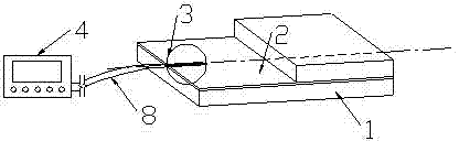
图1为本实用新型实施例桥梁健康的智能测力支座的构造示意图。 Fig. 1 is a structural schematic diagram of an intelligent force-measuring bearing for bridge health according to an embodiment of the present invention. the
图2为本实用新型实施例测力元件的安装示意图。 Fig. 2 is a schematic diagram of the installation of the load-measuring element of the embodiment of the utility model. the
图3为本实用新型实施例光纤传感器的安装示意图。 Fig. 3 is a schematic diagram of the installation of the optical fiber sensor of the embodiment of the present invention. the
图中:1-板式橡胶支座,2-加强钢板,3-光纤应变传感器,4-光纤数据采集转换器,5-玻璃管,6-克维拉纤维,7-光纤连接器,8-导线。 In the figure: 1-plate rubber bearing, 2-reinforced steel plate, 3-optical fiber strain sensor, 4-optical fiber data acquisition converter, 5-glass tube, 6-Kevlar fiber, 7-optical fiber connector, 8-wire . the
具体实施方式 Detailed ways
下面结合附图和具体实施例对本实用新型做进一步说明,以助理解本实用新型的应用,但本实用新型的保护范围并不限于这一具体实施例。 The utility model will be further described below in conjunction with the accompanying drawings and specific embodiments to help understand the application of the utility model, but the protection scope of the utility model is not limited to this specific embodiment. the
参考图1~3,一种桥梁健康的智能测力支座,包括板式橡胶支座1,其特征在于:所述板式橡胶支座1安装有测力元件,所述测力元件包括多个用于感应支座上的轴压力和剪切力且对称设置在板式橡胶支座1内的光纤应变传感器3,所述光纤应变传感器3均连接到将光信号转换成电信号并显示出来的光纤数据采集转换器4,所述光纤数据采集转换器4连接到监测中心。
Referring to Figures 1 to 3, a healthy intelligent force-measuring bearing for a bridge comprises a plate-type rubber bearing 1, and is characterized in that: the plate-type rubber bearing 1 is equipped with a force-measuring element, and the force-measuring element includes a plurality of An optical fiber strain sensor 3 that senses the axial pressure and shear force on the support and is symmetrically arranged in the
在本实施例中,所述测力元件包括两个光纤应变传感器3,所述两个光纤应变传感器3沿板式橡胶支座1中间层的加强钢板2的中轴线对称粘贴,所述板式橡胶支座1和光纤应变传感器3制作成一体。所述光纤应变传感器3的内端部套设有玻璃管5,所述光纤应变传感器3的中间部套设有用于保护的克维拉纤维6,所述光纤应变传感器3的外端部设置有光纤连接器7,所述光纤连接器7经导线8与光纤数据采集转换器4相连接。
In this embodiment, the load cell includes two optical fiber strain sensors 3, and the two optical fiber strain sensors 3 are pasted symmetrically along the central axis of the reinforced steel plate 2 in the middle layer of the plate rubber bearing 1, and the plate rubber bearing The
在本实施例中,该支座通过光纤应变传感器3和外接的光纤数据采集转换器4,可以很方便地感应并显示出支座的受力情况,并实现对支座受力情况的长期、实时的监测,结果可用作桥梁健康监测和寿命评估的依据。
In this embodiment, the support can easily sense and display the stress of the support through the optical fiber strain sensor 3 and the external optical fiber
本实施例还提供一种桥梁健康的监测方法,包括若干个板式橡胶支座1,在各个板式橡胶支座1上分别安装测力元件,所述测力元件包括多个用于感应相应支座上的轴压力和剪切力的光纤应变传感器3;多个光纤应变传感器3对称设置在相应的板式橡胶支座1内,并连接到一个将光信号转换成电信号并以应变形式显示出来的光纤数据采集转换器4;取光纤数据采集转换器4采集的多个光纤应变传感器3的平均值作为最终的支座受力应变测量值,提高了数据采集的安全性和准确性。多个光纤数据采集转换器4通过网络技术连接到监测中心,可实现对多个支座受力情况的实时、自动和联动监测,通过对采集数据的综合计算分析,可实现对整座桥梁结构的健康状况进行诊断、评估和预测。
This embodiment also provides a bridge health monitoring method, which includes several
在本实施例中,所述测力元件包括两个光纤应变传感器3,所述两个光纤应变传感器3沿板式橡胶支座1中间层的加强钢板2的中轴线对称粘贴,所述板式橡胶支座1和光纤应变传感器3制作成一体。所述光纤应变传感器3的内端部用玻璃管5套住,所述光纤应变传感器3的中间部采用克维拉纤维6保护,所述光纤应变传感器3的外端部设置有光纤连接器7,所述光纤连接器7通过导线8与光纤数据采集转换器4相连接。
In this embodiment, the load cell includes two optical fiber strain sensors 3, and the two optical fiber strain sensors 3 are pasted symmetrically along the central axis of the reinforced steel plate 2 in the middle layer of the plate rubber bearing 1, and the plate rubber bearing The
在本实施例中,所述导线8将两个光纤应变传感器3的光信号传递到一个光纤数据采集转换器4;通过光纤数据采集转换器4收集并转换的数据,并根据实验室预先标定的应力与应变关系,可以准确、方便地得到整个支座的受力情况。实验室支座标定方法是通过采用专门设计的一套夹具,将智能测力支座表面受到的竖向压力或水平剪力与光纤数据采集转换器4显示的应变值建立对应关系;夹具的所有板材由厚度为12.7mm的硬质铝材制成,与支座直接接触的铝板表面需先经过喷砂处理,然后涂抹环氧胶,以保证它们间无相对滑动和可以有效传递外力。
In this embodiment, the wire 8 transmits the optical signals of the two optical fiber strain sensors 3 to an optical fiber
以上所述仅为本实用新型的较佳实施例,凡依本实用新型申请专利范围所做的均等变化与修饰,皆应属本实用新型的涵盖范围。 The above descriptions are only preferred embodiments of the present utility model, and all equivalent changes and modifications made according to the patent scope of the present utility model shall fall within the scope of the present utility model. the
Claims (5)
Priority Applications (1)
| Application Number | Priority Date | Filing Date | Title |
|---|---|---|---|
| CN201220019408XU CN202492796U (en) | 2012-01-17 | 2012-01-17 | Intelligent dynamometric support for bridge health |
Applications Claiming Priority (1)
| Application Number | Priority Date | Filing Date | Title |
|---|---|---|---|
| CN201220019408XU CN202492796U (en) | 2012-01-17 | 2012-01-17 | Intelligent dynamometric support for bridge health |
Publications (1)
| Publication Number | Publication Date |
|---|---|
| CN202492796U true CN202492796U (en) | 2012-10-17 |
Family
ID=46999031
Family Applications (1)
| Application Number | Title | Priority Date | Filing Date |
|---|---|---|---|
| CN201220019408XU Expired - Fee Related CN202492796U (en) | 2012-01-17 | 2012-01-17 | Intelligent dynamometric support for bridge health |
Country Status (1)
| Country | Link |
|---|---|
| CN (1) | CN202492796U (en) |
Cited By (4)
| Publication number | Priority date | Publication date | Assignee | Title |
|---|---|---|---|---|
| CN102564660A (en) * | 2012-01-17 | 2012-07-11 | 福州大学 | Method and intelligent force-measuring supporting seat for monitoring bridge health |
| CN105755950A (en) * | 2015-12-31 | 2016-07-13 | 同济大学 | Intelligent optical-fiber inhaul-cable damping support system |
| CN110438891A (en) * | 2019-07-15 | 2019-11-12 | 广州大学 | Friction Pendulum Bearing with Displacement Measurement and Monitoring Function |
| CN113532703A (en) * | 2021-07-20 | 2021-10-22 | 北京隽德科技有限公司 | Intelligent device for real-time force measurement of bridge support |
-
2012
- 2012-01-17 CN CN201220019408XU patent/CN202492796U/en not_active Expired - Fee Related
Cited By (6)
| Publication number | Priority date | Publication date | Assignee | Title |
|---|---|---|---|---|
| CN102564660A (en) * | 2012-01-17 | 2012-07-11 | 福州大学 | Method and intelligent force-measuring supporting seat for monitoring bridge health |
| CN105755950A (en) * | 2015-12-31 | 2016-07-13 | 同济大学 | Intelligent optical-fiber inhaul-cable damping support system |
| CN105755950B (en) * | 2015-12-31 | 2017-04-05 | 同济大学 | Intelligent optical fiber inhaul cable damping support saddle system |
| CN110438891A (en) * | 2019-07-15 | 2019-11-12 | 广州大学 | Friction Pendulum Bearing with Displacement Measurement and Monitoring Function |
| CN110438891B (en) * | 2019-07-15 | 2024-04-02 | 广州大学 | Friction pendulum support with displacement measurement and monitoring functions |
| CN113532703A (en) * | 2021-07-20 | 2021-10-22 | 北京隽德科技有限公司 | Intelligent device for real-time force measurement of bridge support |
Similar Documents
| Publication | Publication Date | Title |
|---|---|---|
| CN102564660A (en) | Method and intelligent force-measuring supporting seat for monitoring bridge health | |
| CN102519652B (en) | Bolt pre-tightening force testing device and control method thereof | |
| CN109388865B (en) | Tower emergency failure early warning method under ground settlement working condition | |
| CN110082023A (en) | A kind of real-time monitoring for cable force device and monitoring method | |
| CN107271090A (en) | A kind of aircraft wing moment of flexure method of real-time based on fiber grating | |
| CN203116893U (en) | Hidden weld joint stress monitoring device for orthotropic steel bridge decks | |
| CN202492796U (en) | Intelligent dynamometric support for bridge health | |
| CN106321968A (en) | Spring support hanger with automatic monitoring, analyzing and early warning functions | |
| CN107014528B (en) | A wheel-rail force online monitoring system, monitoring method and static calibration method | |
| CN102928145B (en) | Method for detecting absolute stress of prestressed concrete bridge | |
| CN114136776B (en) | Measurement and evaluation system and evaluation method for assembled steel-concrete beam connection structure | |
| CN106677231A (en) | Refined measurement method for pile body deformation of cast-in-place pile | |
| CN101762351B (en) | A Method for Measuring the Tension Force of Tie Rods in Large Buildings | |
| CN204666102U (en) | Flush type airfield pavement FBG strain monitoring device | |
| CN206112258U (en) | Spring hangers and support with automatic monitoring analysis and warning function | |
| CN105606617A (en) | Device and method for measuring fatigue crack propagation rule of CFRP reinforced steel structure | |
| CN205506038U (en) | Fiber bragg grating sensor ware based on settlement measurement of transformer substation | |
| CN207741790U (en) | A kind of long Bridge Structure online health monitoring device safely | |
| CN206627446U (en) | Reinforcing bar corrosion optical fiber sensing monitoring devices | |
| CN214250869U (en) | Distributed optical fiber sensing device capable of monitoring steel beam cracks | |
| CN106896108B (en) | An optical fiber sensing and monitoring device for steel bar corrosion | |
| CN206037977U (en) | Fracture width changes dynamic monitoring device based on response of meeting an emergency | |
| CN102831665B (en) | Power transmission tower intensity and vibration off-line intelligent routing inspection system and early warning method thereof | |
| CN106382894A (en) | Fiber grating multidirectional sensor | |
| CN108519061B (en) | Method and device for measuring deformation strain gradient of component |
Legal Events
| Date | Code | Title | Description |
|---|---|---|---|
| C14 | Grant of patent or utility model | ||
| GR01 | Patent grant | ||
| CF01 | Termination of patent right due to non-payment of annual fee |
Granted publication date: 20121017 Termination date: 20150117 |
|
| EXPY | Termination of patent right or utility model |