CN202492016U - Foam pump - Google Patents
Foam pump Download PDFInfo
- Publication number
- CN202492016U CN202492016U CN2011205569646U CN201120556964U CN202492016U CN 202492016 U CN202492016 U CN 202492016U CN 2011205569646 U CN2011205569646 U CN 2011205569646U CN 201120556964 U CN201120556964 U CN 201120556964U CN 202492016 U CN202492016 U CN 202492016U
- Authority
- CN
- China
- Prior art keywords
- channel
- passage
- spray
- foam pump
- air valve
- Prior art date
- Legal status (The legal status is an assumption and is not a legal conclusion. Google has not performed a legal analysis and makes no representation as to the accuracy of the status listed.)
- Expired - Lifetime
Links
Images


Landscapes
- Closures For Containers (AREA)
Abstract
一种泡沫泵,用以吸取容器内的液体且使该液体自喷嘴喷出泡沫,由压头、旋盖和气缸构成外壳,还包括气阀和滤网支架,其特征在于,所述压头内设置喷孔,所述气阀设置在喷孔的下方,喷孔和气阀之间形成一喷液通道,所述滤网支架设置在喷液通道内,滤网支架包括上端部、中间块和下端部,其中,上端部和下端部同一朝向,并分别位于喷液通道的上方和下方,横向占设部分喷液通道形成一混合腔,中间块位于上端部和下端部之间,其设置方向与上端部和下端部朝向相反,并横向抵设在喷液通道内,上端部留空的部分喷液通道与中间块之间形成一第一通道,下端部留空的部分喷液通道与中间块之间形成第二通道,混合腔分别与第一通道、第二通道通过滤网贯通。本实用新型采用独特的滤网结构,使得高温烫滤网时只需要一次即可,时间短,而且非常方便。

A foam pump is used to absorb liquid in a container and make the liquid spray foam from a nozzle. The housing is composed of a pressure head, a screw cap and a cylinder, and also includes an air valve and a filter bracket. The characteristics are that a spray hole is arranged in the pressure head, the air valve is arranged below the spray hole, a spray channel is formed between the spray hole and the air valve, the filter bracket is arranged in the spray channel, the filter bracket includes an upper end, a middle block and a lower end, wherein the upper end and the lower end are in the same direction and are respectively located above and below the spray channel, a part of the spray channel is transversely occupied to form a mixing chamber, the middle block is located between the upper end and the lower end, and its setting direction is opposite to that of the upper end and the lower end, and it is transversely arranged in the spray channel, a first channel is formed between the part of the spray channel left empty at the upper end and the middle block, a second channel is formed between the part of the spray channel left empty at the lower end and the middle block, and the mixing chamber is respectively connected with the first channel and the second channel through the filter. The utility model adopts a unique filter structure, so that the high-temperature scalding filter only needs one time, the time is short, and it is very convenient.
Description
技术领域 technical field
本实用新型涉及一种泡沫泵,特别是对滤网支架进行改动的泡沫泵。 The utility model relates to a foam pump, in particular to a foam pump with modified filter screen supports. the
背景技术 Background technique
现有泡沫泵由出口相通的抽吸气缸和抽吸液缸组成,其中,抽吸气缸由气缸体和活塞构成,液缸上带进出液单向阀,抽吸气缸的活塞与抽吸液缸的活塞相连,使用时按压压头使抽吸气缸的活塞与抽吸液缸的活塞同步工作,抽吸液缸将容器乳粹吸入、抽吸气缸将空气吸入,然后乳液和空气在出口处相混合变成泡沫喷出,但这种结构成本高。 The existing foam pump is composed of a suction cylinder and a suction liquid cylinder whose outlets are connected. The suction cylinder is composed of a cylinder body and a piston. When in use, press the pressure head to make the piston of the suction cylinder and the piston of the suction liquid cylinder work synchronously. The suction liquid cylinder sucks the emulsion of the container, and the suction cylinder sucks the air, and then the emulsion and air are combined at the outlet. Mixing becomes foam spraying, but this structure is costly. the
另外,专利号ZL2005200636954公开了另一种类型的泡沫泵,包括缸体、按头、塞管和弹簧,其特点是缸体内设有同轴的液缸和气缸,液缸下位于缸体的中央、气缸位于液缸的外围,气缸与按头下部的环形翼相配,液缸与塞管端的外径相配,限位柱限位环与塞管的限位扣相配,限位柱下部的头部与液缸下部的进液口构成进液单向阀,限位柱下部设有倒钩勾住进液口,阀芯与塞管组成出液单向阀,塞管、阀芯和液缸之间围成吸排液腔;塞管与按头之间用阀座连接,弹簧设在阀座与气缸之间,气缸、塞管、阀座之间围成吸排气腔,阀座下端设有径向伸出的环形下阀片,阀座上部沿轴向伸出的环形上阀片;出气单向阀和出液单向阀的出口连通按头的喷嘴。 In addition, Patent No. ZL2005200636954 discloses another type of foam pump, which includes a cylinder body, a press head, a plug tube and a spring. The center and the air cylinder are located on the periphery of the liquid cylinder, the air cylinder matches the annular wing at the lower part of the press head, the liquid cylinder matches the outer diameter of the plug tube end, the limit post limit ring matches the stop buckle of the plug tube, and the head at the bottom of the limit post The upper part and the liquid inlet at the lower part of the liquid cylinder form a liquid inlet one-way valve. The lower part of the limit column is provided with a barb to hook the liquid inlet. The valve core and the plug tube form a liquid outlet one-way valve. A suction and discharge cavity is formed between them; the plug tube and the press head are connected by a valve seat, the spring is set between the valve seat and the cylinder, the suction and discharge cavity is surrounded by the cylinder, the plug tube, and the valve seat, and the lower end of the valve seat is set There is an annular lower valve plate protruding radially, and an annular upper valve plate protruding axially from the upper part of the valve seat; the outlets of the air outlet check valve and the liquid outlet check valve are connected to the nozzle of the press head. the
上述的泡沫泵存在以下问题: The above-mentioned foam pump has the following problems:
首先,泡沫泵适用于化妆品等领域时,现有的滤网网管入口端设粗滤网、出口端设置细滤网,要分别对粗滤网和细滤网进行两次高温烫滤网处理,不仅时序长,而且成本高。 First of all, when the foam pump is suitable for cosmetics and other fields, the existing filter mesh tube inlet end is provided with a coarse filter mesh, and the outlet end is provided with a fine filter mesh. Not only the timing is long, but also the cost is high. the
接着,现有的泡沫泵中,弹簧内置于气缸,与化学料体直接接触,存在腐蚀生锈的问题。 Next, in the existing foam pump, the spring is built into the cylinder, which is in direct contact with the chemical material body, and there is a problem of corrosion and rust. the
随后,现有的泡沫泵中,采用整体式活塞,密封性较差。 Subsequently, in the existing foam pump, the integral piston is adopted, and the sealing performance is relatively poor. the
实用新型内容 Utility model content
本实用新型的目的在于提供一种泡沫泵,以解决现有泡沫泵中要对粗滤网和细滤网进行两次高温烫滤网处理、成本高的技术问题。 The purpose of the utility model is to provide a foam pump to solve the technical problem of high-cost scalding of the coarse filter and the fine filter twice in the existing foam pump. the
一种泡沫泵,用以吸取容器内的液体且使该液体自喷嘴喷出泡沫,由压头、旋盖和气缸构成外壳,还包括气阀和滤网支架,其特征在于,所述压头内设置喷孔,所述气阀设置在喷孔的下方,喷孔和气阀之间形成一喷液通道,所述滤网支架设置在喷液通道内,滤网支架包括上端部、中间块和下端部,其中,上端部和下端部同一朝向,并分别位于喷液通道的上方和下方,横向占设部分喷液通道形成一混合腔,中间块位于上端部和下端部之间,其设置方 向与上端部和下端部朝向相反,并横向抵设在喷液通道内,上端部留空的部分喷液通道与中间块之间形成一第一通道,下端部留空的部分喷液通道与中间块之间形成第二通道,混合腔分别与第一通道、第二通道通过滤网贯通。 A kind of foam pump, used for absorbing the liquid in the container and making the liquid spray foam from the nozzle, the casing is composed of a pressure head, a screw cap and a cylinder, and also includes an air valve and a filter screen support, characterized in that the pressure head The spray hole is arranged inside, the air valve is arranged below the spray hole, a liquid spray channel is formed between the spray hole and the air valve, the filter screen support is arranged in the liquid spray channel, and the filter screen support includes an upper end, a middle block and The lower end, wherein, the upper end and the lower end are in the same direction, and are respectively located above and below the liquid spray channel, and a part of the liquid spray channel is horizontally occupied to form a mixing chamber, and the middle block is located between the upper end and the lower end. The direction is opposite to the upper end and the lower end, and it is transversely arranged in the liquid spray channel. A first channel is formed between the part of the liquid spray channel left empty at the upper end and the middle block, and the part of the liquid spray channel left empty at the lower end is connected to the A second channel is formed between the middle blocks, and the mixing chamber communicates with the first channel and the second channel respectively through the filter screen. the
较佳地,混合腔与第一通道通过细滤网贯通。 Preferably, the mixing chamber communicates with the first channel through a fine filter. the
较佳地,混合腔与第二通道通过粗滤网贯通。 Preferably, the mixing chamber communicates with the second passage through a coarse filter. the
较佳地,上端部、中间块和下端部分别呈半圆形或弧形,以和喷液通道相吻合。 Preferably, the upper end, the middle block and the lower end are semicircular or arc-shaped respectively, so as to coincide with the liquid spraying channel. the
较佳地,中间块通过一侧支架分别与上端部、下端部连接。 Preferably, the middle block is respectively connected to the upper end and the lower end through one side bracket. the
较佳地,中间块上、下分别设置上侧梁柱和下侧梁柱,所述上侧梁柱、下侧梁柱分别设置在第一通道和第二通道内,并且分别与上端部和下端部齐平。 Preferably, the upper and lower sides of the middle block are respectively provided with an upper side beam column and a lower side beam column, and the upper side beam column and the lower side beam column are respectively arranged in the first channel and the second channel, and are connected to the upper end and The lower end is flush. the
与现有技术相比,本实用新型具有以下优点: Compared with the prior art, the utility model has the following advantages:
(1)本实用新型采用独特的滤网结构,使得高温烫滤网时只需要一次即可,时间短,而且非常方便。 (1) The utility model adopts a unique filter screen structure, so that it only needs to be scalded once at high temperature, which is short and very convenient. the
(2)在本实用新型中,弹簧外置于气缸内,与化学料体不直接接触,不存在腐蚀生锈的问题。 (2) In the utility model, the spring is placed outside the cylinder and does not directly contact with the chemical material body, so there is no problem of corrosion and rust. the
(3)在本实用新型的泡沫泵中,采用液体泵吸装置,克服了现有的密封性差的问题。 (3) In the foam pump of the present invention, a liquid pumping device is used to overcome the existing problem of poor sealing. the
附图说明 Description of drawings
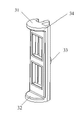
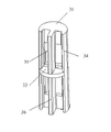
图1A、图1B、图1C分别为本实用新型滤网支架的立体图和截面图; Fig. 1A, Fig. 1B, Fig. 1C are respectively the three-dimensional view and the sectional view of filter screen support of the present utility model;
图2、图3分别为泡沫泵使用状态下及复原状态下的结构剖示图; Fig. 2 and Fig. 3 are the structure cut-away diagrams of the foam pump in use state and recovery state respectively;
图4为外壳内结构剖示意图。 Fig. 4 is a schematic cross-sectional view of the inner structure of the housing. the
具体实施方式 Detailed ways
以下按照附图,具体说明本实用新型。 Below according to accompanying drawing, specifically illustrate the utility model. the
请参阅图1A、图1B、图1C,滤网支架包括上端部31、中间块33和下端部32,其中, 上端部31和下端部32同一朝向,并分别位于喷液通道的上方和下方,横向占设部分喷液通道形成一混合腔,中间块33位于上端部31和下端部32之间,其设置方向与上端部和下端部的朝向相反,并横向抵设在喷液通道内,上端部留空的部分喷液通道与中间块之间形成一第一通道,下端部留空的部分喷液通道与中间块33之间形成第二通道,混合腔分别与第一通道、第二通道通过滤网贯通。
Please refer to Fig. 1A, Fig. 1B, Fig. 1C, filter screen support comprises
混合腔与第一通道通过细滤网302贯通。混合腔与第二通道通过粗滤网301贯通。
The mixing chamber communicates with the first passage through a
为了更佳的密封性,上端部31、中间块33和下端部32分别呈半圆形或弧形,以和喷液通道相吻合。中间块33通过一侧支架34分别与上端部、下端部连接。另外,中间块33上、下分别设置上侧梁柱35和下侧梁柱36,上侧梁柱35、下侧梁柱36分别设置在第一通道和第二通道内,并且分别与上端部31和下端部33齐平。气体和液体能在第一通道、第二通道及混合腔进行全面混合,形成非常好的泡沫,并且,这种结构设计使得高温烫滤网时只需要一次即可,时间短,而且非常方便。
For better sealing performance, the
实例一 Example one
请参阅图1至图6,一种泡沫泵,用以吸取容器内的液体且使该液体自喷嘴喷出泡沫,由压头2、旋盖7和气缸10构成外壳,外壳内依序包括压头2、气阀4、主柱5、大活塞6、旋盖7、连接杆8、小活塞9、气缸10、弹簧和阀门12,在压头2与气阀4间设有网管,弹簧设在主柱5外,其中:
Please refer to Fig. 1 to Fig. 6, a kind of foam pump is used for absorbing the liquid in the container and making the liquid spray foam from the nozzle.
一压头2,其上设有喷嘴201供泡沫喷出,压头2套接管下部有一扩径部,在扩径部内壁设有环状凹槽或卡槽,且在扩径部起始处形成一环形凸阶;
A
一滤网支架3,从下方伸入套接管内,滤网支架3(如图1所示)的下端与气阀4连通;
A filter screen support 3 extends into the sleeve pipe from below, and the lower end of the filter screen support 3 (as shown in Figure 1) communicates with the
一气阀4为管状结构,中部设有周缘向下且带凸边部的圆环,压头2抵在圆环上方,圆环内壁设进气槽401,气阀4下方管内壁设有排气槽402,气阀4上方的管壁外径与套接管内壁匹配并相互套接固定;
An
一主柱5,为呈中空结构的管体,由一周缘向下的环部将管体分为套管部和管状部,环部上表面设有围在套管部外周的挡圈501,套管部与气阀4下方管路连通,管内形成混合室502,主柱5下方外径收缩形成凸台;
A
一大活塞6带有上、下环口,套在主柱5和气阀4之间的管状部外,大活塞6的外壁与气缸10内壁接触,上环口的壁面与气阀4圆环内壁贴合,大活塞6内壁斜向下设有密封圈 601,大活塞6上还设有气孔602和气槽;
A
一连接杆8,其上段部穿入主柱5的管状部504并与主柱5联动,其外缘上设有一个及一个以上的轴向导料渠道,其下段部呈一环状的止档部801,被抽吸的流体顺导料渠道沿主杆进入混合室502内;
A connecting
一小活塞9活动套置于连接杆8下部,外周与气缸10内壁接触,分别具有一上环口及下环口,主柱5下方抵在上环口内,且可由于往复运动与止檔部801配合完成流体关或开的出料动作,该下环口与止檔部801间开启时形成有一间隙通道,作为液料阀口;
The movable sleeve of a
一气缸体10,套设于大活塞6和小活塞9外周且呈一上大下小渐缩折贯通管状体,并具有一段口径较大且容纳主柱5环部及以上的部位,一段口径较小的下端部容置套接了连接杆8的管状部504,在该上端部与下端部间接合内壁上形成一弹簧座,该下端部下方具有一较小径的入口,该入口设一单向阀门12;
A
一大弹簧11,置于该主柱5外,一端与弹簧座抵靠,另一端与主柱5的环部抵顶,以提供主柱5一向上的回复力;
A
一小弹簧13,套接在主柱5管状部外周,一端与管状部抵顶,另一端伸在小活塞9上环口内,使小活塞9被弹性抵顶;
A
为方便与容器连接,所述的气缸体之下端部下方设有一与容器连接的衔接口部。 In order to facilitate the connection with the container, a connecting port connected with the container is provided below the lower end of the cylinder block. the
所述的小活塞9下环口与止檔部间开启时形成有一间隙通道,作为液料出料阀口。
When the lower ring opening of the
所述的气缸体10下端部壁上更设有一气孔,该气孔能使气缸体与外部空气导通,以平衡由于液体喷出后气缸体内的空气压力。
The lower end wall of the
所述的气阀4内设有卡位环,卡位环抵顶主柱5套管部的顶端。
The
一小弹簧13套在主柱5收缩部外,一端抵顶在主柱5下方外径收缩形成凸台处,另一端伸入小活塞9上环口内。
A
当挤压压头2往下运动时,带动气阀4和主柱5一起运动,大活塞6和小活塞9由于受气缸10管壁磨擦作用而静止不动,此时出料阀口逐渐打开,位于气阀4上的进气槽401逐渐被关闭,密封圈601逐渐脱离挡圈501而使排气通道打开,并在不断下压的过程中将气缸10内的气体从气缸10经过挡圈501与密封圈601之间的缝隙排入气槽603,然后进入混合室502,与随下压过程中经过出料阀口进入混合室502的液体进行混合,然后,经过滤网管3产生泡沫,并从压头2喷嘴挤出。
When the
当松开压头2时,由于受大弹簧11复位作用力作用,使主柱5和气阀4一起往上运动,此时大活塞6与小活塞9受气缸管壁磨擦力作用而静止不动,使小活塞9处出料阀口关闭, 大活塞6与气阀4之间的进气槽401打开,挡圈501与大活塞6密封圈601之间的通道关闭,并使密封圈601抱紧气阀4,使其密封,随主柱5与连接杆8不断往上运动,带动大活塞6和小活塞9往上运动,分别使气缸10内的气室1001与液室1002的体积增大,从而外部空气从气阀4进气槽401吸入,经设置于大活塞6上的气孔602和气槽603进入气室1001,容器内的液料经阀门12被吸入液室1002,为下次泵料做准备。
When the
本实用新型弹簧不与液体接触,不会对液体造成污染,另外,又由于大活塞与小活塞可以不联动,提供了优异的密封性。 The spring of the utility model is not in contact with the liquid and will not pollute the liquid. In addition, because the large piston and the small piston can not be linked together, excellent sealing performance is provided. the
其中,网管外也可不设凸环,网管3直接抵顶压头2内管道顶部。
Wherein, the convex ring may not be provided outside the network pipe, and the network pipe 3 directly touches the top of the inner pipe of the
上次说明,上述泡沫泵的结构仅做说明,并非用于局限于本实用新型。 As explained last time, the structure of the above-mentioned foam pump is only for illustration, and is not intended to limit the utility model. the
以上公开的仅为本申请的一个具体实施例,但本申请并非局限于此,任何本领域的技术人员能思之的变化,都应落在本申请的保护范围内。 What is disclosed above is only a specific embodiment of the present application, but the present application is not limited thereto, and any changes conceivable by those skilled in the art shall fall within the protection scope of the present application. the
Claims (6)
Priority Applications (1)
| Application Number | Priority Date | Filing Date | Title |
|---|---|---|---|
| CN2011205569646U CN202492016U (en) | 2011-12-28 | 2011-12-28 | Foam pump |
Applications Claiming Priority (1)
| Application Number | Priority Date | Filing Date | Title |
|---|---|---|---|
| CN2011205569646U CN202492016U (en) | 2011-12-28 | 2011-12-28 | Foam pump |
Publications (1)
| Publication Number | Publication Date |
|---|---|
| CN202492016U true CN202492016U (en) | 2012-10-17 |
Family
ID=46998253
Family Applications (1)
| Application Number | Title | Priority Date | Filing Date |
|---|---|---|---|
| CN2011205569646U Expired - Lifetime CN202492016U (en) | 2011-12-28 | 2011-12-28 | Foam pump |
Country Status (1)
| Country | Link |
|---|---|
| CN (1) | CN202492016U (en) |
Cited By (2)
| Publication number | Priority date | Publication date | Assignee | Title |
|---|---|---|---|---|
| CN102502061A (en) * | 2011-12-28 | 2012-06-20 | 王雅灿 | Foam pump |
| CN109415144A (en) * | 2016-06-30 | 2019-03-01 | 花王株式会社 | Foam discharge container |
-
2011
- 2011-12-28 CN CN2011205569646U patent/CN202492016U/en not_active Expired - Lifetime
Cited By (5)
| Publication number | Priority date | Publication date | Assignee | Title |
|---|---|---|---|---|
| CN102502061A (en) * | 2011-12-28 | 2012-06-20 | 王雅灿 | Foam pump |
| CN102502061B (en) * | 2011-12-28 | 2014-12-03 | 德晋(香港)控股有限公司 | Foam pump |
| CN109415144A (en) * | 2016-06-30 | 2019-03-01 | 花王株式会社 | Foam discharge container |
| CN109415144B (en) * | 2016-06-30 | 2020-07-07 | 花王株式会社 | Foam discharge container |
| US11090664B2 (en) | 2016-06-30 | 2021-08-17 | Kao Corporation | Foam discharge container |
Similar Documents
| Publication | Publication Date | Title |
|---|---|---|
| CN202638659U (en) | Double Spring Spray Pump | |
| CN105083730B (en) | Elastomeric bladder foam pump | |
| CN102285484A (en) | Foam pump | |
| CN202765494U (en) | Foam pump | |
| CN103867431A (en) | New structure of one-way valve for plunger pump of high-pressure cleaning machine | |
| CN102502061A (en) | Foam pump | |
| CN201721750U (en) | Novel foam pump | |
| CN202492016U (en) | Foam pump | |
| CN104210745B (en) | Foam pump | |
| CN104843312B (en) | Improved Rotary Telescopic Vacuum Nozzle and Its Application Method | |
| CN203635393U (en) | Atomizing pump with dustproof cover | |
| CN206885720U (en) | A kind of press type shower nozzle | |
| CN202226188U (en) | Foam pump | |
| CN102502062A (en) | Foam pump | |
| CN105197389B (en) | Foam pump | |
| CN204642567U (en) | Improved type rotary and telescopic vacuum shower nozzle | |
| CN220866083U (en) | Extrusion foam pump | |
| CN201664249U (en) | Novel soap dispenser | |
| CN117772448A (en) | Foam pump capable of discharging evenly | |
| CN204642562U (en) | Liquid quantitative squeezer | |
| CN205570611U (en) | Plastics spraying pump head | |
| CN205172866U (en) | Pump core structure | |
| CN201750877U (en) | A new type of pump | |
| CN204137600U (en) | A liquid vacuum bottle | |
| CN203635389U (en) | Novel atomizing pump device with sealing cup |
Legal Events
| Date | Code | Title | Description |
|---|---|---|---|
| C14 | Grant of patent or utility model | ||
| GR01 | Patent grant | ||
| ASS | Succession or assignment of patent right |
Owner name: DEJIN (HONG KONG) HOLDINGS CO., LTD. Free format text: FORMER OWNER: WANG YACAN Effective date: 20140509 |
|
| C41 | Transfer of patent application or patent right or utility model | ||
| COR | Change of bibliographic data |
Free format text: CORRECT: ADDRESS; FROM: TAIWAN, CHINA TO: HONG KONG, CHINA |
|
| TR01 | Transfer of patent right |
Effective date of registration: 20140509 Address after: Room 20, building 2008, Jardine House, 1 Kangle Plaza, central, Hongkong, China Patentee after: De Jin (Hongkong) Holding Limited Address before: Hsinchu City, Taiwan, China Patentee before: Wang Yacan |
|
| AV01 | Patent right actively abandoned |
Granted publication date: 20121017 Effective date of abandoning: 20141203 |
|
| AV01 | Patent right actively abandoned |
Granted publication date: 20121017 Effective date of abandoning: 20141203 |
|
| RGAV | Abandon patent right to avoid regrant |