CN202492015U - A New Type of Vacuum Bottle Pump Head Structure - Google Patents
A New Type of Vacuum Bottle Pump Head Structure Download PDFInfo
- Publication number
- CN202492015U CN202492015U CN2011205063761U CN201120506376U CN202492015U CN 202492015 U CN202492015 U CN 202492015U CN 2011205063761 U CN2011205063761 U CN 2011205063761U CN 201120506376 U CN201120506376 U CN 201120506376U CN 202492015 U CN202492015 U CN 202492015U
- Authority
- CN
- China
- Prior art keywords
- piston
- model
- pressure head
- spring
- head structure
- Prior art date
- Legal status (The legal status is an assumption and is not a legal conclusion. Google has not performed a legal analysis and makes no representation as to the accuracy of the status listed.)
- Expired - Fee Related
Links
Images


Classifications
-
- B—PERFORMING OPERATIONS; TRANSPORTING
- B05—SPRAYING OR ATOMISING IN GENERAL; APPLYING FLUENT MATERIALS TO SURFACES, IN GENERAL
- B05B—SPRAYING APPARATUS; ATOMISING APPARATUS; NOZZLES
- B05B11/00—Single-unit hand-held apparatus in which flow of contents is produced by the muscular force of the operator at the moment of use
- B05B11/01—Single-unit hand-held apparatus in which flow of contents is produced by the muscular force of the operator at the moment of use characterised by the means producing the flow
- B05B11/10—Pump arrangements for transferring the contents from the container to a pump chamber by a sucking effect and forcing the contents out through the dispensing nozzle
- B05B11/1001—Piston pumps
- B05B11/1023—Piston pumps having an outlet valve opened by deformation or displacement of the piston relative to its actuating stem
-
- B—PERFORMING OPERATIONS; TRANSPORTING
- B05—SPRAYING OR ATOMISING IN GENERAL; APPLYING FLUENT MATERIALS TO SURFACES, IN GENERAL
- B05B—SPRAYING APPARATUS; ATOMISING APPARATUS; NOZZLES
- B05B11/00—Single-unit hand-held apparatus in which flow of contents is produced by the muscular force of the operator at the moment of use
- B05B11/01—Single-unit hand-held apparatus in which flow of contents is produced by the muscular force of the operator at the moment of use characterised by the means producing the flow
- B05B11/10—Pump arrangements for transferring the contents from the container to a pump chamber by a sucking effect and forcing the contents out through the dispensing nozzle
- B05B11/1042—Components or details
- B05B11/1043—Sealing or attachment arrangements between pump and container
- B05B11/1046—Sealing or attachment arrangements between pump and container the pump chamber being arranged substantially coaxially to the neck of the container
- B05B11/1047—Sealing or attachment arrangements between pump and container the pump chamber being arranged substantially coaxially to the neck of the container the pump being preassembled as an independent unit before being mounted on the container
-
- B—PERFORMING OPERATIONS; TRANSPORTING
- B05—SPRAYING OR ATOMISING IN GENERAL; APPLYING FLUENT MATERIALS TO SURFACES, IN GENERAL
- B05B—SPRAYING APPARATUS; ATOMISING APPARATUS; NOZZLES
- B05B11/00—Single-unit hand-held apparatus in which flow of contents is produced by the muscular force of the operator at the moment of use
- B05B11/01—Single-unit hand-held apparatus in which flow of contents is produced by the muscular force of the operator at the moment of use characterised by the means producing the flow
- B05B11/10—Pump arrangements for transferring the contents from the container to a pump chamber by a sucking effect and forcing the contents out through the dispensing nozzle
- B05B11/1042—Components or details
- B05B11/1066—Pump inlet valves
- B05B11/1067—Pump inlet valves actuated by pressure
- B05B11/1069—Pump inlet valves actuated by pressure the valve being made of a resiliently deformable material or being urged in a closed position by a spring
-
- B—PERFORMING OPERATIONS; TRANSPORTING
- B05—SPRAYING OR ATOMISING IN GENERAL; APPLYING FLUENT MATERIALS TO SURFACES, IN GENERAL
- B05B—SPRAYING APPARATUS; ATOMISING APPARATUS; NOZZLES
- B05B11/00—Single-unit hand-held apparatus in which flow of contents is produced by the muscular force of the operator at the moment of use
- B05B11/01—Single-unit hand-held apparatus in which flow of contents is produced by the muscular force of the operator at the moment of use characterised by the means producing the flow
- B05B11/10—Pump arrangements for transferring the contents from the container to a pump chamber by a sucking effect and forcing the contents out through the dispensing nozzle
- B05B11/1042—Components or details
- B05B11/1073—Springs
- B05B11/1074—Springs located outside pump chambers
Landscapes
- Jet Pumps And Other Pumps (AREA)
Abstract
Description
技术领域 technical field
本实用新型涉及真空瓶,具体是指一种新型的真空瓶泵头结构。 The utility model relates to a vacuum bottle, in particular to a novel vacuum bottle pump head structure. the
背景技术 Background technique
现有的真空瓶是一般在圆柱体成椭圆体容器上安装带有活塞的泵头。它的设计原理是用金属弹簧的收缩力,且不让空气进入瓶中,造成真空状态,而利用大气压力来推动瓶底的活塞前进。但是由于弹簧力及大气压力不能给予足够力量,因此活塞不能与瓶壁贴合太紧,否则活塞将因阻力过大而无法上升前进;反之,若要让活塞易前进又容易出现漏料情况,因此真空瓶故障率非常高。现有的真空瓶真空泵压头的结构过于复杂,材料不利于回收利用,成本也比较高。 Existing vacuum bottle is that the pump head that has piston is generally installed on cylinder into ellipsoidal container. Its design principle is to use the contraction force of the metal spring to prevent air from entering the bottle, resulting in a vacuum state, and to use atmospheric pressure to push the piston at the bottom of the bottle forward. However, since the spring force and atmospheric pressure cannot give enough force, the piston cannot be too tightly attached to the bottle wall, otherwise the piston will not be able to rise and move forward due to excessive resistance; Therefore, the vacuum bottle failure rate is very high. The structure of the pressure head of the existing vacuum bottle vacuum pump is too complicated, the material is not conducive to recycling, and the cost is relatively high. the
实用新型内容 Utility model content
本实用新型需解决的问题是提供一种结构简单、密封性能好、可以反复使用、工作可靠稳定的新型的真空瓶泵头结构。 The problem to be solved by the utility model is to provide a novel vacuum bottle pump head structure with simple structure, good sealing performance, repeated use, reliable and stable operation. the
本实用新型可以通过以下技术方案来实现: The utility model can be realized through the following technical solutions:
本实用新型公开了一种新型的真空瓶泵头结构,包括压头、泵体、连接杆、活塞和牙套,所述的牙套设有上腔室和下腔室,压头设置在上腔室中并能在上腔室中上下活动,压头的出液端部与连接杆连接,连接杆的另 一端安装有活塞,所述的活塞设置在泵体中,所述的压头的出液端部连接有弹簧扣,弹簧扣的另一端与扣环连接,所述的扣环安装在上腔室的底部,在弹簧扣上安装有弹簧。 The utility model discloses a novel pump head structure of a vacuum bottle, which comprises a pressure head, a pump body, a connecting rod, a piston and a tooth cover. The tooth cover is provided with an upper chamber and a lower chamber, and the pressure head is arranged in the upper chamber. and can move up and down in the upper chamber, the liquid outlet end of the pressure head is connected with the connecting rod, the other end of the connecting rod is equipped with a piston, the piston is arranged in the pump body, the liquid outlet of the pressure head The end is connected with a spring clasp, and the other end of the spring clasp is connected with a clasp, and the clasp is installed at the bottom of the upper chamber, and a spring is installed on the spring clasp. the
所述的连接杆套装在弹簧扣中。 The connecting rod is sleeved in the spring clasp. the
所述的扣环的上下端分别设置有螺纹槽,上端的螺纹槽与弹簧扣的下端螺纹连接,下端的螺纹槽与泵体的上端螺纹连接。 The upper and lower ends of the clasp are respectively provided with threaded grooves, the upper threaded grooves are threadedly connected with the lower end of the spring clasp, and the lower threaded grooves are threadedly connected with the upper end of the pump body. the
所述的泵体的下端设置有活动阀。 The lower end of the pump body is provided with a movable valve. the
所述的牙套的下腔室中设置有内螺纹。 The lower chamber of the dental cover is provided with an internal thread. the
本实用新型真空瓶泵头结构由压头弹簧扣、弹簧、扣环、泵体、连接杆、活塞、活动阀、牙套组成的真空瓶泵头,它将弹簧设置在弹簧扣的外部,在牙套的上腔室里,使弹簧不会有机会接触到瓶内的物料,可以保证弹簧长久耐用;活塞采用精密活塞,可以实现很好的密封和吸气功能;活动阀代替传统的球阀,可以使活塞往上运动时会打开进入液体,活塞往下运动时起密封作用。本实用新型的真空瓶泵头结构独特,采用外弹簧结构设计,弹簧不会接处到液体起环保作用,活动阀采用独特的设计不会上下跳,使泵头产生的吸力大而且稳定。 The vacuum bottle pump head structure of the utility model is a vacuum bottle pump head composed of a pressure head spring buckle, a spring, a buckle ring, a pump body, a connecting rod, a piston, a movable valve, and a tooth cover. In the upper chamber of the upper chamber, the spring will not have the opportunity to contact the material in the bottle, which can ensure the long-term durability of the spring; the piston adopts a precision piston, which can achieve good sealing and suction functions; the movable valve replaces the traditional ball valve, which can make the When the piston moves upward, it will open to enter the liquid, and when the piston moves downward, it will act as a seal. The vacuum bottle pump head of the utility model has a unique structure, adopts an outer spring structure design, and the spring will not be connected to the liquid to play an environmental protection role. The movable valve adopts a unique design and will not jump up and down, so that the suction generated by the pump head is large and stable. the
附图说明 Description of drawings
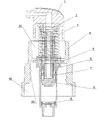
附图1为本实用新型的真空瓶泵头结构的结构示意图;
Accompanying
附图2为图1中的压头结构示意图;
附图3为图1中的弹簧扣结构示意图;
Accompanying
附图4为图1中的弹簧结构示意图;
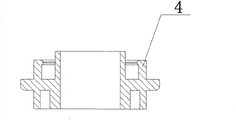
附图5为图1中的扣环结构示意图;
附图6为图1中的泵体结构示意图;
附图7为图1中的连接杆结构示意图;
Accompanying
附图8为图1中的活塞结构示意图;
附图9为图1中的活动阀结构示意图;
附图10为图1中的牙套结构示意图。 Accompanying drawing 10 is the schematic diagram of the structure of the mouthpiece in Fig. 1 . the
具体实施方式 Detailed ways
下面将结合说明书附图来对本实用新型作进一步描述: The utility model will be further described below in conjunction with the accompanying drawings:
如附图1~图10所示,本实用新型公开了一种新型的真空瓶泵头结构,包括压头1、泵体5、连接杆6、活塞7和牙套9,所述的牙套9设有上腔室91和下腔室92,压头1设置在上腔室91中并能在上腔室91中上下活动,压头1的出液端部与连接杆6连接,连接杆6的另一端安装有活塞7,所述的活塞7设置在泵体5中,所述的压头1的出液端部连接有弹簧扣2,弹簧扣2的另一端与扣环4连接,所述的扣环4安装在上腔室91的底部,在弹簧扣2上安装有弹簧3。所述的连接杆6套装在弹簧扣2中。所述的扣环4的上下端分别设置有螺纹槽,上端的螺纹槽与弹簧扣2的下端螺纹连接,下端的螺纹槽与泵体5的上端螺纹连接。所述的泵体5的下端设置有活动阀8。所述的牙套9的下腔室92中设置有内螺纹93。
As shown in accompanying
本实用新型的工作过程是:按压压头1,连接杆6带动活塞7往下运动,此时活动阀8关闭,当压头1在弹簧3的作用下往上弹回时,活塞7往上运动,此时活动阀8打开,液体被吸入到连接杆6,再压一下压头1, 液体即从压头1的出液端部输出。本实用新型的采用活动阀8代替传统的球阀,当活塞7往上运动时,活动阀8会打开,活塞7产生的吸力将液体带入,当活塞7往下运动时,活动阀8会关闭,将起密封作用。本实用新型的结构独特,将弹簧设置在外部,弹簧不会接触到液体,可以弹簧长久耐用,同时也便于清洁,起环保作用,活动阀采用独特的设计不会上下跳,从而使泵头产生的吸力大稳定性强。
The working process of the utility model is: press the
以上所述,仅为本实用新型的较佳实施例而已,并非对本实用新型作任何形式上的限制;凡本行业的普通技术人员均可按说明书附图所示和以上所述而顺畅地实施本实用新型;但是,凡熟悉本专业的技术人员在不脱离本实用新型技术方案范围内,可利用以上所揭示的技术内容而作出的些许更动、修饰与演变的等同变化,均为本实用新型的等效实施例;同时,凡依据本实用新型的实质技术对以上实施例所作的任何等同变化的更动、修饰与演变等,均仍属于本实用新型的技术方案的保护范围之内。 The above is only a preferred embodiment of the utility model, and is not intended to limit the utility model in any way; any ordinary skilled person in the industry can smoothly implement it as shown in the accompanying drawings and the above description This utility model; however, any equivalent change, modification and evolution that can be made by using the technical content disclosed above without departing from the scope of the technical solution of the utility model by those familiar with the profession are all equivalent changes of the utility model. New equivalent embodiments; at the same time, all changes, modifications and evolutions of any equivalent changes made to the above embodiments according to the substantive technology of the utility model still belong to the protection scope of the technical solution of the utility model. the
Claims (5)
Priority Applications (1)
| Application Number | Priority Date | Filing Date | Title |
|---|---|---|---|
| CN2011205063761U CN202492015U (en) | 2011-12-06 | 2011-12-06 | A New Type of Vacuum Bottle Pump Head Structure |
Applications Claiming Priority (1)
| Application Number | Priority Date | Filing Date | Title |
|---|---|---|---|
| CN2011205063761U CN202492015U (en) | 2011-12-06 | 2011-12-06 | A New Type of Vacuum Bottle Pump Head Structure |
Publications (1)
| Publication Number | Publication Date |
|---|---|
| CN202492015U true CN202492015U (en) | 2012-10-17 |
Family
ID=46998252
Family Applications (1)
| Application Number | Title | Priority Date | Filing Date |
|---|---|---|---|
| CN2011205063761U Expired - Fee Related CN202492015U (en) | 2011-12-06 | 2011-12-06 | A New Type of Vacuum Bottle Pump Head Structure |
Country Status (1)
| Country | Link |
|---|---|
| CN (1) | CN202492015U (en) |
Cited By (4)
| Publication number | Priority date | Publication date | Assignee | Title |
|---|---|---|---|---|
| CN105035505A (en) * | 2015-08-06 | 2015-11-11 | 宁波正庄喷雾器有限公司 | Perfume pump with external spring |
| CN105644918A (en) * | 2016-01-11 | 2016-06-08 | 上海承轩包装科技有限公司 | Environment-friendly type shower nozzle |
| CN109760940A (en) * | 2019-01-25 | 2019-05-17 | 深圳洛可可工业设计有限公司 | A kind of press type container |
| CN109878884A (en) * | 2019-03-27 | 2019-06-14 | 深圳市诚致生物开发有限公司 | A kind of grease vacuum packaging bottle |
-
2011
- 2011-12-06 CN CN2011205063761U patent/CN202492015U/en not_active Expired - Fee Related
Cited By (5)
| Publication number | Priority date | Publication date | Assignee | Title |
|---|---|---|---|---|
| CN105035505A (en) * | 2015-08-06 | 2015-11-11 | 宁波正庄喷雾器有限公司 | Perfume pump with external spring |
| CN105644918A (en) * | 2016-01-11 | 2016-06-08 | 上海承轩包装科技有限公司 | Environment-friendly type shower nozzle |
| CN109760940A (en) * | 2019-01-25 | 2019-05-17 | 深圳洛可可工业设计有限公司 | A kind of press type container |
| CN109760940B (en) * | 2019-01-25 | 2024-05-24 | 深圳洛可可工业设计有限公司 | A push-type container |
| CN109878884A (en) * | 2019-03-27 | 2019-06-14 | 深圳市诚致生物开发有限公司 | A kind of grease vacuum packaging bottle |
Similar Documents
| Publication | Publication Date | Title |
|---|---|---|
| CN203582445U (en) | Quantitative filling mechanism | |
| CN202492015U (en) | A New Type of Vacuum Bottle Pump Head Structure | |
| CN202346098U (en) | A kind of environment-friendly suction pump | |
| CN204971669U (en) | Water pick | |
| CN102069051B (en) | Lotion pump | |
| CN201525583U (en) | Novel emulsion pump | |
| CN201825408U (en) | Novel external spring device foam pump | |
| CN202038550U (en) | Vacuum bottle cap | |
| CN202193293U (en) | Glue bottle cover with brush head adjustable in length | |
| CN201979869U (en) | Pressing ink pumping device | |
| CN201406130Y (en) | a liquid nozzle | |
| CN202553565U (en) | Safety valve of coffee maker | |
| CN215099335U (en) | Pump pressure type coupling agent device | |
| CN218717441U (en) | Lower ball valve structure for plunger pump of spraying machine | |
| CN203791093U (en) | Plastic sealing cup atomizing pump | |
| CN201750877U (en) | A new type of pump | |
| CN204820835U (en) | Cap of ink bottle | |
| CN206026463U (en) | Novel oral care is towards suction gun | |
| CN202326171U (en) | Exhauster for pump head in cleaning machine | |
| CN222401893U (en) | A pollution-proof and drip-proof push-type lotion pump head | |
| CN208625728U (en) | A kind of CT bulb is changed oil exhaust system | |
| CN203635384U (en) | Lengthened nozzle type sprayer | |
| CN203635391U (en) | Sprayer with good sealing performance | |
| CN206024964U (en) | Portable trematode ware | |
| CN205312170U (en) | Play to imitate fast novel pistol pump unit |
Legal Events
| Date | Code | Title | Description |
|---|---|---|---|
| C14 | Grant of patent or utility model | ||
| GR01 | Patent grant | ||
| CF01 | Termination of patent right due to non-payment of annual fee |
Granted publication date: 20121017 Termination date: 20151206 |
|
| EXPY | Termination of patent right or utility model |