CN202491699U - Connecting structure of chair steel tube and stamping part - Google Patents
Connecting structure of chair steel tube and stamping part Download PDFInfo
- Publication number
- CN202491699U CN202491699U CN2012200427183U CN201220042718U CN202491699U CN 202491699 U CN202491699 U CN 202491699U CN 2012200427183 U CN2012200427183 U CN 2012200427183U CN 201220042718 U CN201220042718 U CN 201220042718U CN 202491699 U CN202491699 U CN 202491699U
- Authority
- CN
- China
- Prior art keywords
- steel pipe
- stamping part
- boss
- steel tube
- blanked part
- Prior art date
- Legal status (The legal status is an assumption and is not a legal conclusion. Google has not performed a legal analysis and makes no representation as to the accuracy of the status listed.)
- Expired - Fee Related
Links
Images



Landscapes
- Branch Pipes, Bends, And The Like (AREA)
Abstract
Description
技术领域 technical field
本实用新型涉及汽车座椅领域,具体地涉及座椅的钢管与冲压件的连接结构。 The utility model relates to the field of automobile seats, in particular to a connection structure between steel pipes and stamping parts of the seat.
背景技术 Background technique
一般,汽车座椅的高度调节机构需将其钢管与调高冲压件刚性连接起来,才能有效实现座椅的高度调节功能,目前最常见的钢管与冲压件的刚性连接方式采用弧焊固定连接,但采用焊接难以控制,例如钢管与冲压件的相对位置尺寸难以保证、焊接处发生变形、熔深、表面有气孔、组件表面有焊渣等问题,这些都会影响高度调节机构的工作性能,而且焊接缺陷的组件易发生脱焊,从而导致座椅高度调节机构失效,为了改善钢管与冲压件采用焊接来刚性连接的缺陷,专利CN200920210230中,提到一种不通过焊接就可实现钢管与冲压件的刚性连接的连接结构,即通过所需设备,在钢管左端部或右端部胀形出第一凸台,然后装配上冲压件,再通过所需设备在该钢管端部膨胀出第二凸台,且使冲压件夹持在第一凸台和第二凸台之间,使冲压件既不能沿钢管轴向运动也不能绕钢管转动,该刚性连接方式很好地绕过了焊接时很难处理的材料可焊性、熔深、表面气孔、焊渣等问题,但该种连接结构存在缺陷,即在工作一定时间或次数后,冲压件与凸台内壁接触表面磨损后,冲压件受一定载荷可能相对钢管发生转动移位或相对转动,使得高度调节机构性能部分丧失或完全丧失。 In general, the height adjustment mechanism of the car seat needs to rigidly connect its steel pipe with the height-adjusting stamping part to effectively realize the height adjustment function of the seat. At present, the most common rigid connection method between the steel pipe and the stamping part is fixed connection by arc welding. However, it is difficult to control by welding, for example, it is difficult to ensure the relative position and size of the steel pipe and the stamping part, the deformation of the welding place, the depth of penetration, the pores on the surface, and the welding slag on the surface of the components, etc., all of which will affect the working performance of the height adjustment mechanism, and welding Defective components are prone to desoldering, which leads to the failure of the seat height adjustment mechanism. In order to improve the defect of rigid connection of steel pipes and stamping parts by welding, patent CN200920210230 mentions a steel pipe and stamping parts that can be realized without welding. The connection structure of rigid connection, that is, through the required equipment, the first boss is formed on the left or right end of the steel pipe, and then the stamping parts are assembled, and the second boss is expanded on the end of the steel pipe through the required equipment. And the stamping part is clamped between the first boss and the second boss, so that the stamping part can neither move axially nor rotate around the steel pipe. This rigid connection method bypasses the difficult handling during welding However, there are defects in this connection structure, that is, after a certain time or times of work, after the contact surface between the stamping part and the inner wall of the boss is worn, the stamping part is subject to a certain load Rotational displacement or relative rotation may occur relative to the steel pipe, so that the performance of the height adjustment mechanism is partially lost or completely lost.
实用新型内容 Utility model content
本实用新型为提高座椅钢管与冲压件刚性连接的可靠性,提供一种能完全防止冲压件相对钢管转动或者松脱的钢管与冲压件连接结构,以提高座椅的高度调节机构的工作性能。 In order to improve the reliability of the rigid connection between the seat steel pipe and the stamping part, the utility model provides a connection structure between the steel pipe and the stamping part that can completely prevent the stamping part from rotating or loosening relative to the steel pipe, so as to improve the working performance of the height adjustment mechanism of the seat .
本实用新型的一种座椅钢管与冲压件连接结构,包括所述钢管的圆形管壁、在所述钢管的第一端部胀形出的第一凸台和第二凸台、以及位于第一端部上的冲压件的连接孔,所述冲压件通过所述连接孔穿套在所述钢管的圆形管壁上并夹持在所述第一凸台和第二凸台之间,所述冲压件的连接孔的孔壁与所述钢管的圆形管壁之间形成有填充空间,且所述钢管形成有向该填充空间填充的以限制所述冲压件相对钢管转动的填充部。 A connection structure between a seat steel pipe and a stamping part of the utility model comprises a circular pipe wall of the steel pipe, a first boss and a second boss formed at the first end of the steel pipe, and a The connecting hole of the stamping part on the first end, the stamping part passes through the connecting hole on the circular pipe wall of the steel pipe and is clamped between the first boss and the second boss A filling space is formed between the hole wall of the connecting hole of the stamping part and the circular pipe wall of the steel pipe, and the steel pipe is formed with a filler that fills the filling space to limit the rotation of the stamping part relative to the steel pipe department.
应该注意,上述钢管的第一端部既可是钢管的左端部也可以是钢管的右端部,左端部和右端部分别指钢管的一端和另一端。 It should be noted that the above-mentioned first end of the steel pipe can be either the left end or the right end of the steel pipe, and the left end and the right end refer to one end and the other end of the steel pipe respectively.
经过进一步改进,所述冲压件的连接孔设有至少一个孔槽,所述填充空间为连接孔的孔槽与所述钢管的圆形管壁形成的空间。 After further improvement, the connecting hole of the stamping part is provided with at least one hole, and the filling space is the space formed by the hole of the connecting hole and the circular pipe wall of the steel pipe.
经过进一步改进,所述冲压件的连接孔为花键孔,所述孔槽为花键孔槽。 After further improvement, the connecting hole of the punching part is a spline hole, and the hole groove is a spline hole groove.
经过进一步改进,所述第一凸台和/或第二凸台为绕钢管圆形管壁径向向外的环形凸起形状。 After further improvement, the first boss and/or the second boss is in the shape of an annular protrusion radially outward around the circular pipe wall of the steel pipe.
通过本实用新型的一种座椅钢管与冲压件连接结构的技术方案可知,通过钢管胀形出第一凸台限制冲压件向钢管轴向的一个方向移动,冲压件的连接孔的孔壁与所述钢管的圆形管壁之间形成有填充空间,使钢管形成有向该填充空间填充的填充部以限制所述冲压件相对钢管转动,同时在位于冲压件背离第一凸台的一侧的钢管上胀形出第二凸台,以限制冲压件沿钢管轴向的另一个方向移动,故不仅能消除完全靠焊接引起的钢管与冲压件的连接缺陷,也能消除单靠冲压件两侧的凸台夹紧冲压件以限制冲压件相对钢管转动时出现转动松动的缺陷,因而大大提高了钢管与冲压件连接的可靠性,从而提高了座椅调高机构的工作性能。 According to the technical scheme of the connection structure between the seat steel pipe and the stamping part of the utility model, it can be seen that the first boss is formed by the expansion of the steel pipe to restrict the movement of the stamping part to the axial direction of the steel pipe, and the wall of the connecting hole of the stamping part is in line with the A filling space is formed between the circular pipe walls of the steel pipe, so that the steel pipe is formed with a filling portion filling the filling space to limit the rotation of the stamping part relative to the steel pipe. The second boss is bulged on the steel pipe to limit the movement of the stamping part in the other direction of the steel pipe axis, so it can not only eliminate the connection defect between the steel pipe and the stamping part caused by welding alone, but also eliminate the two parts of the stamping part alone. The boss on the side clamps the stamping part to limit the defect of loose rotation when the stamping part rotates relative to the steel pipe, thus greatly improving the reliability of the connection between the steel pipe and the stamping part, thereby improving the working performance of the seat height adjustment mechanism.
附图说明 Description of drawings
图1为本实用新型提供的一种座椅钢管与冲压件连接结构的一种实施方式的主视图。 Fig. 1 is a front view of an embodiment of a connection structure between a seat steel pipe and a stamping part provided by the present invention.
图2为本实用新型提供的一种座椅钢管与冲压件连接结构的一种实施方式的A-A剖视图。 Fig. 2 is an A-A cross-sectional view of an embodiment of a connection structure between a seat steel pipe and a stamping part provided by the utility model.
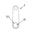
图3为本实用新型提供的一种座椅钢管与冲压件连接结构的一种实施方式的冲压件的主视图。 Fig. 3 is a front view of a stamping part of an embodiment of a connection structure between a seat steel pipe and a stamping part provided by the present invention.
图4为本实用新型提供的一种座椅钢管与冲压件连接结构的一种实施方式的B-B剖视图。 Fig. 4 is a B-B cross-sectional view of an embodiment of a connection structure between a seat steel pipe and a stamping part provided by the utility model.
具体实施方式 Detailed ways
为了使本实用新型所解决的技术问题、技术方案及有益效果更加清楚明白,以下结合附图及实施例,对本实用新型进行进一步详细说明。应当理解,此处所描述的具体实施例仅仅用以解释本实用新型,并不用于限定本实用新型。 In order to make the technical problems, technical solutions and beneficial effects solved by the utility model clearer, the utility model will be further described in detail below in conjunction with the accompanying drawings and embodiments. It should be understood that the specific embodiments described here are only used to explain the utility model, and are not intended to limit the utility model.
如图1至图4所示,本实施例的一种座椅钢管与冲压件连接结构,包括所述钢管1的圆形管壁11、在所述钢管1的左端部(即钢管一端)胀形出的第一凸台12和第二凸台14、以及位于钢管1左端部上的冲压件2的连接孔21,所述冲压件2通过所述连接孔21穿套在所述钢管1的圆形管壁11上并夹持在所述第一凸台12和第二凸台14之间,所述冲压件2的连接孔21的孔壁与所述钢管1的圆形管壁11之间形成有填充空间,且所述钢管1形成有向该填充空间填充的以限制所述冲压件2相对钢管1转动的填充部13,应该注意,由于这里所说的填充空间是用来填充部13向其内填充以限制冲压件2相对钢管1转动的,所以这里所说的填充空间在其绕钢管1轴线旋转方向上存在填充空间的壁,也就是说,填充部13在绕钢管1轴线旋转方向上存在与填充空间的壁接触,从而能限制冲压件2相对钢管1转动。本实施例在钢管1的右端部(即钢管的另一端)也胀形有第一凸台12和第二凸台14,使位于该端的冲压件2与左端的冲压件2一样采用相同的连接结构与钢管1连接,但应该注意,钢管两端也可以与两端相应的冲压件2采用不同的连接结构也可,例如钢管1任一一端与相应的冲压件采用上述连接结构连接,而另一端与相应的冲压件则采用传统的焊接方式连接。
As shown in Figures 1 to 4, a connection structure between a seat steel pipe and a stamping part in this embodiment includes a
考虑到钢管1管壁厚度比较薄,故一般先用设备在钢管1端部胀形出第一凸台12,然后装配上冲压件2,再用设备对钢管施力使钢管1材料向填充空间填充,以形成填充部13,同时在位于冲压件2背离第一凸台12的一侧的钢管1上胀形出第二凸台14,从而将冲压件2夹持在第一凸台12和第二凸台14之间以限制冲压件2沿钢管1轴向移动,第一凸台13和第二凸台14能有效防止冲压件2沿钢管1轴向移动,而填充部13能有效防止冲压件2相对钢管1转动,故大大提高了座椅的钢管1与冲压件2的刚性连接的可靠性,从而大大提高了座椅调高机构的工作性能。
Considering that the wall thickness of the
本实施例的所述冲压件2的连接孔21设有至少一个孔槽211,所述填充空间为连接孔21的孔槽211与所述钢管1的圆形管壁11形成的空间,一般花键联接能有效防止转动件相对于转轴转动,故本实施例的冲压件2的连接孔21设计成花键孔,孔槽211为花键孔槽。
The connecting
为了更好地对冲压件2轴向限位,本实施例的第一凸台12和第二凸台14设计成绕钢管1圆形管壁11径向向外凸起的环形凸起形状,当然,也可以只对两者之一设计成环形凸起形状。
In order to better limit the axial position of the
以上所述仅为本实用新型的较佳实施例而已,并不用以限制本实用新型,凡在本实用新型的精神和原则之内所作的任何修改、等同替换和改进等,均应包含在本实用新型的保护范围之内。 The above descriptions are only preferred embodiments of the present utility model, and are not intended to limit the present utility model. Any modifications, equivalent replacements and improvements made within the spirit and principles of the present utility model shall be included in this utility model. within the scope of protection of utility models.
Claims (4)
Priority Applications (1)
| Application Number | Priority Date | Filing Date | Title |
|---|---|---|---|
| CN2012200427183U CN202491699U (en) | 2012-02-10 | 2012-02-10 | Connecting structure of chair steel tube and stamping part |
Applications Claiming Priority (1)
| Application Number | Priority Date | Filing Date | Title |
|---|---|---|---|
| CN2012200427183U CN202491699U (en) | 2012-02-10 | 2012-02-10 | Connecting structure of chair steel tube and stamping part |
Publications (1)
| Publication Number | Publication Date |
|---|---|
| CN202491699U true CN202491699U (en) | 2012-10-17 |
Family
ID=46997938
Family Applications (1)
| Application Number | Title | Priority Date | Filing Date |
|---|---|---|---|
| CN2012200427183U Expired - Fee Related CN202491699U (en) | 2012-02-10 | 2012-02-10 | Connecting structure of chair steel tube and stamping part |
Country Status (1)
| Country | Link |
|---|---|
| CN (1) | CN202491699U (en) |
-
2012
- 2012-02-10 CN CN2012200427183U patent/CN202491699U/en not_active Expired - Fee Related
Similar Documents
| Publication | Publication Date | Title |
|---|---|---|
| CN102785543B (en) | Suspension structure and link arranging method | |
| CN202613032U (en) | Steel ball seat | |
| CN202327418U (en) | Pipe union | |
| CN202491698U (en) | Connecting structure of chair steel tube and stamping part | |
| JP5595702B2 (en) | Torque rod | |
| CN204387480U (en) | Solenoid directional control valve support and solenoid directional control valve thereof | |
| CN107719019A (en) | Self-locking disc brake wheel rim, wheel rim make positioner and wheel rim preparation method | |
| CN203651942U (en) | Floating front overhang swing arm assembly of cab | |
| CN206429559U (en) | A kind of contact net catenary working car | |
| CN205078965U (en) | Cover is withheld to vehicle air conditioner system pipeline | |
| CN202280092U (en) | Excavator, excavator movable arm and support connecting structure thereof | |
| JP2009018692A (en) | Power cylinder bracket mounting structure | |
| CN204309549U (en) | The connection structure of swing arm sleeve pipe and swing arm sleeve pipe and bush of swing arm | |
| CN204053851U (en) | Tool shaft for detecting rotation balance of rotating part | |
| CN202546076U (en) | Rotary joint | |
| CN202518363U (en) | Automobile oil port mounting box | |
| CN201827377U (en) | Rubber bellows mechanical seal | |
| CN111043345A (en) | Bisection ball valve | |
| CN204419342U (en) | A kind of vibration-damping radiator | |
| CN105752168A (en) | Automobile fender support assembly and manufacturing method | |
| CN203046797U (en) | Lower connector component of shock absorber | |
| JP2016060459A (en) | knuckle | |
| CN209505349U (en) | A drive axle housing with a triangular plate structure | |
| JP2018071417A (en) | Compressor welding method and compressor | |
| CN207278256U (en) | Flexible damping type clutch |
Legal Events
| Date | Code | Title | Description |
|---|---|---|---|
| C14 | Grant of patent or utility model | ||
| GR01 | Patent grant | ||
| CF01 | Termination of patent right due to non-payment of annual fee | ||
| CF01 | Termination of patent right due to non-payment of annual fee |
Granted publication date: 20121017 Termination date: 20210210 |