CN202491383U - Ejection structure of injection mold - Google Patents
Ejection structure of injection mold Download PDFInfo
- Publication number
- CN202491383U CN202491383U CN2012200573616U CN201220057361U CN202491383U CN 202491383 U CN202491383 U CN 202491383U CN 2012200573616 U CN2012200573616 U CN 2012200573616U CN 201220057361 U CN201220057361 U CN 201220057361U CN 202491383 U CN202491383 U CN 202491383U
- Authority
- CN
- China
- Prior art keywords
- thimble
- ejector pin
- flat
- injection mold
- utility
- Prior art date
- Legal status (The legal status is an assumption and is not a legal conclusion. Google has not performed a legal analysis and makes no representation as to the accuracy of the status listed.)
- Expired - Fee Related
Links
Images

Landscapes
- Moulds For Moulding Plastics Or The Like (AREA)
- Injection Moulding Of Plastics Or The Like (AREA)
Abstract
Description
技术领域 technical field
本实用新型涉及一种注塑模具,具体地说是一种注塑模具的顶出结构。 The utility model relates to an injection mold, in particular to an ejection structure of an injection mold.
背景技术 Background technique
塑胶产品一般由注塑模具完成其成型过程。制造过程一般为,先将熔胶注入到注塑模具的型腔内,然后冷却成型,接着开模将产品由模具中的顶出结构从注塑模具内顶出,使产品彻底脱模。在产品顶出的过程中,要尽可能保护产品的完整,使其具有较佳的成型效果。然而,现有的顶出结构将产品顶出时极容易造成产品粘着斜顶,导致自动化的机械手失效,需要工人手动操作,才能将产品顺利取出。生产效率较低,还增加了人工成本。 Plastic products are generally formed by injection molds. The manufacturing process is generally as follows: first inject the melt into the cavity of the injection mold, then cool and form, and then open the mold to eject the product from the injection mold through the ejection structure in the mold, so that the product is completely demoulded. In the process of product ejection, it is necessary to protect the integrity of the product as much as possible so that it has a better molding effect. However, when the existing ejection structure ejects the product, it is very easy to cause the product to stick to the inclined top, resulting in the failure of the automatic manipulator, and the manual operation of the worker is required to take out the product smoothly. The production efficiency is low, and the labor cost is also increased.
发明内容 Contents of the invention
本实用新型要解决的技术问题是提供一种能将产品顺利顶出、工作效率高的注塑模具的顶出结构。 The technical problem to be solved by the utility model is to provide an ejection structure of an injection mold that can eject products smoothly and has high working efficiency.
为了解决上述技术问题,本实用新型采取以下技术方案: In order to solve the above technical problems, the utility model takes the following technical solutions:
一种注塑模具的顶出结构,包括顶针底板、顶针面板、动模板及顶针,顶针面板与顶针底板相固定,所述顶出结构还包括扁顶针,扁顶针下部套装有行程限位套,行程限位套与顶针面板相固定,扁顶针下端与设在顶针底板内的压缩弹簧相装接。 An ejection structure of an injection mold, comprising an ejector base plate, an ejector panel, a movable template and an ejector pin, the ejector panel and the ejector base plate are fixed, the ejection structure also includes a flat ejector pin, the lower part of the flat ejector pin is fitted with a stroke limit sleeve, and the stroke The limit sleeve is fixed with the thimble panel, and the lower end of the flat thimble is connected with the compression spring arranged in the thimble bottom plate.
进一步地,所述顶针底板内设有与扁顶针相装接的垫针,弹簧套装在垫针上,垫针上端抵顶着扁顶针下端。 Further, the bottom plate of the thimble is provided with a backing pin attached to the flat thimble, the spring is sleeved on the backing pin, and the upper end of the backing pin is against the lower end of the flat thimble.
本实用新型优化了模具结构,通过限制扁顶针的顶出行程,使产品顺利的被顶出,确保模具的自动化生产,提高了生产效率,适合产品的大批量生产。 The utility model optimizes the mold structure, and by limiting the ejection stroke of the flat ejector pin, the product is ejected smoothly, ensures the automatic production of the mold, improves the production efficiency, and is suitable for mass production of products.
附图说明 Description of drawings
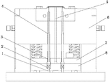
图1为本实用新型主视结构示意图; Fig. 1 is a schematic diagram of the main view structure of the utility model;
图2为本实用新型顶出产品的过程示意图; Fig. 2 is the schematic diagram of the process of ejecting the product of the utility model;
图3为本实用新型将产品顶出后的示意图。 Fig. 3 is a schematic diagram of the utility model after the product is ejected.
具体实施方式 Detailed ways
为了便于本领域技术人员的理解,下面结合附图对本实用新型作进一步的描述。 In order to facilitate the understanding of those skilled in the art, the utility model will be further described below in conjunction with the accompanying drawings.
如图1所示,本实用新型揭示了一种注塑模具的顶出结构,包括顶针底板8、顶针面板7、动模板6及顶针5,顶针面板7与顶针底板8相固定,所述顶出结构还设有扁顶针4,扁顶针4下部套装有行程限位套3,行程限位套3与顶针面板7相固定,扁顶针4下端与设在顶针底板8内的压缩弹簧2相装接。选择压缩弹簧2时,压缩弹簧2的弹力必须大于注塑产品的包紧力,这样才能使扁顶针4与其他机构同时顶出,保证扁顶针4的顺利顶出。顶针底板8内设有与扁顶针4相装接的垫针1,弹簧2套装在垫针1上,垫针1上端抵顶着扁顶针4下端,有效防止扁顶针4下沉。
As shown in Figure 1, the utility model discloses an ejection structure of an injection mold, which includes an
如图2所示,在顶出过程中,顶针底板8和顶针面板7向上运动,扁顶针4和顶针5一起向上同时顶出,随着不断向上运动,行程限位套3随着上升并与动模板6接触被卡住,扁顶针4停止顶出,而此时整个产品的顶出行程还未完成。如图3所示,注塑模具的顶针5继续向上移动而将产品顶出,使产品脱离扁顶针4,一个工作周期完成。完成过程中产品不会粘接或卡在扁顶针上,确保自动生产,保证工作效率。
As shown in Figure 2, during the ejection process, the
本实用新型注塑模具的顶出结构通过限制扁顶针的行程,使其顶出时具有延迟功能,使产品能顺畅的顶出。 The ejection structure of the injection mold of the utility model limits the stroke of the flat ejector pin, so that it has a delay function when ejecting, so that the product can be ejected smoothly.
上述实施例仅例示性说明本实用新型的原理及其功效,以及部分运用的实施例,对于本领域的普通技术人员来说,在不脱离本实用新型创造构思的前提下,还可以做出若干变形和改进,这些都属于本实用新型权利要求的保护范围。 The above-mentioned embodiments only illustrate the principles and effects of the present utility model, as well as the partially used embodiments. For those of ordinary skill in the art, without departing from the inventive concept of the present utility model, some Variations and improvements all belong to the protection scope of the claims of the present invention.
Claims (2)
Priority Applications (1)
| Application Number | Priority Date | Filing Date | Title |
|---|---|---|---|
| CN2012200573616U CN202491383U (en) | 2012-02-22 | 2012-02-22 | Ejection structure of injection mold |
Applications Claiming Priority (1)
| Application Number | Priority Date | Filing Date | Title |
|---|---|---|---|
| CN2012200573616U CN202491383U (en) | 2012-02-22 | 2012-02-22 | Ejection structure of injection mold |
Publications (1)
| Publication Number | Publication Date |
|---|---|
| CN202491383U true CN202491383U (en) | 2012-10-17 |
Family
ID=46997622
Family Applications (1)
| Application Number | Title | Priority Date | Filing Date |
|---|---|---|---|
| CN2012200573616U Expired - Fee Related CN202491383U (en) | 2012-02-22 | 2012-02-22 | Ejection structure of injection mold |
Country Status (1)
| Country | Link |
|---|---|
| CN (1) | CN202491383U (en) |
-
2012
- 2012-02-22 CN CN2012200573616U patent/CN202491383U/en not_active Expired - Fee Related
Similar Documents
| Publication | Publication Date | Title |
|---|---|---|
| CN102806639A (en) | A secondary ejection mechanism for an injection mold | |
| CN205310722U (en) | Novel second grade ejection mechanism | |
| CN201361970Y (en) | Injection mold ejecting mechanism | |
| CN202344784U (en) | Inclined top sliding ejection structure | |
| CN205167472U (en) | Ejecting mould structure of cubic | |
| CN205905327U (en) | About going position first reset structure at mouth of a river down | |
| CN207772305U (en) | A mold base for easy demoulding | |
| CN206367123U (en) | A kind of dust cover is from ejection die | |
| CN202293240U (en) | Ejection mechanism of injection mold | |
| CN104985758A (en) | Injection mold capable of preventing product from being damaged under pulling | |
| CN204149468U (en) | Flexible glue cast gate delayed ejection structure | |
| CN103381650A (en) | An ejector structure for plastic molds | |
| CN208468958U (en) | A kind of injection mold | |
| CN204546932U (en) | Injection mould runner separating mechanism | |
| CN211307169U (en) | Structure for integrated sleeve beer of insert and product | |
| CN108312448B (en) | Runner ejection structure | |
| CN107877796A (en) | A kind of mould of surface trimming cast gate | |
| CN205467126U (en) | Take off runner mechanism in advance | |
| CN205835867U (en) | Automatically drop structure at a kind of flexible glue mould mouth of a river | |
| CN204526019U (en) | Second ejection mold | |
| CN203331366U (en) | Secondary ejection mechanism of double-injection mould | |
| CN205310726U (en) | Ejecting mould of gas cap | |
| CN205905257U (en) | Secondary ejection mechanism of mould | |
| CN203888139U (en) | Mould capable of automatically separating water gap | |
| CN204526018U (en) | Delay ejection mold |
Legal Events
| Date | Code | Title | Description |
|---|---|---|---|
| C14 | Grant of patent or utility model | ||
| GR01 | Patent grant | ||
| CP01 | Change in the name or title of a patent holder | ||
| CP01 | Change in the name or title of a patent holder |
Address after: Changan town in Guangdong province Dongguan City Zhen'an 523860 corner management section of Dongguan Jin Sheng precision components Limited by Share Ltd Patentee after: Guangdong wins smart group Limited by Share Ltd Address before: Changan town in Guangdong province Dongguan City Zhen'an 523860 corner management section of Dongguan Jin Sheng precision components Limited by Share Ltd Patentee before: Dongguan Janus Precision Components Co., Ltd. |
|
| CF01 | Termination of patent right due to non-payment of annual fee | ||
| CF01 | Termination of patent right due to non-payment of annual fee |
Granted publication date: 20121017 Termination date: 20200222 |