CN202491234U - Tube vice support and substrate used together with tube vice support - Google Patents
Tube vice support and substrate used together with tube vice support Download PDFInfo
- Publication number
- CN202491234U CN202491234U CN 201120321189 CN201120321189U CN202491234U CN 202491234 U CN202491234 U CN 202491234U CN 201120321189 CN201120321189 CN 201120321189 CN 201120321189 U CN201120321189 U CN 201120321189U CN 202491234 U CN202491234 U CN 202491234U
- Authority
- CN
- China
- Prior art keywords
- substrate
- vice support
- support
- tube vice
- tube
- Prior art date
- Legal status (The legal status is an assumption and is not a legal conclusion. Google has not performed a legal analysis and makes no representation as to the accuracy of the status listed.)
- Expired - Lifetime
Links
- 239000000758 substrate Substances 0.000 title claims abstract description 202
- 230000008093 supporting effect Effects 0.000 claims abstract description 120
- 238000007493 shaping process Methods 0.000 claims description 42
- 230000001105 regulatory effect Effects 0.000 claims description 5
- 230000002093 peripheral effect Effects 0.000 claims description 3
- 238000003462 Bender reaction Methods 0.000 abstract 1
- 230000000875 corresponding effect Effects 0.000 description 12
- 239000000463 material Substances 0.000 description 8
- 238000005452 bending Methods 0.000 description 3
- 230000008859 change Effects 0.000 description 3
- 238000009499 grossing Methods 0.000 description 3
- 229910052751 metal Inorganic materials 0.000 description 3
- 239000002184 metal Substances 0.000 description 3
- 230000004048 modification Effects 0.000 description 3
- 238000012986 modification Methods 0.000 description 3
- 230000008901 benefit Effects 0.000 description 2
- 238000005516 engineering process Methods 0.000 description 2
- 238000000034 method Methods 0.000 description 2
- 239000000203 mixture Substances 0.000 description 2
- 230000008569 process Effects 0.000 description 2
- 229910000838 Al alloy Inorganic materials 0.000 description 1
- 229910000760 Hardened steel Inorganic materials 0.000 description 1
- 208000005168 Intussusception Diseases 0.000 description 1
- FYYHWMGAXLPEAU-UHFFFAOYSA-N Magnesium Chemical compound [Mg] FYYHWMGAXLPEAU-UHFFFAOYSA-N 0.000 description 1
- 241000500461 Podostemum ceratophyllum Species 0.000 description 1
- 230000009471 action Effects 0.000 description 1
- 239000004411 aluminium Substances 0.000 description 1
- 229910052782 aluminium Inorganic materials 0.000 description 1
- XAGFODPZIPBFFR-UHFFFAOYSA-N aluminium Chemical compound [Al] XAGFODPZIPBFFR-UHFFFAOYSA-N 0.000 description 1
- 239000002131 composite material Substances 0.000 description 1
- 150000001875 compounds Chemical class 0.000 description 1
- 230000002596 correlated effect Effects 0.000 description 1
- 230000001419 dependent effect Effects 0.000 description 1
- 230000008021 deposition Effects 0.000 description 1
- 238000010586 diagram Methods 0.000 description 1
- 239000011777 magnesium Substances 0.000 description 1
- 229910052749 magnesium Inorganic materials 0.000 description 1
- 230000013011 mating Effects 0.000 description 1
- 238000000465 moulding Methods 0.000 description 1
- 230000003019 stabilising effect Effects 0.000 description 1
- 239000002023 wood Substances 0.000 description 1
Images


Classifications
-
- B—PERFORMING OPERATIONS; TRANSPORTING
- B25—HAND TOOLS; PORTABLE POWER-DRIVEN TOOLS; MANIPULATORS
- B25H—WORKSHOP EQUIPMENT, e.g. FOR MARKING-OUT WORK; STORAGE MEANS FOR WORKSHOPS
- B25H1/00—Work benches; Portable stands or supports for positioning portable tools or work to be operated on thereby
- B25H1/06—Work benches; Portable stands or supports for positioning portable tools or work to be operated on thereby of trestle type
-
- B—PERFORMING OPERATIONS; TRANSPORTING
- B25—HAND TOOLS; PORTABLE POWER-DRIVEN TOOLS; MANIPULATORS
- B25H—WORKSHOP EQUIPMENT, e.g. FOR MARKING-OUT WORK; STORAGE MEANS FOR WORKSHOPS
- B25H1/00—Work benches; Portable stands or supports for positioning portable tools or work to be operated on thereby
- B25H1/08—Work benches; Portable stands or supports for positioning portable tools or work to be operated on thereby with provision for attachment of work holders
-
- B—PERFORMING OPERATIONS; TRANSPORTING
- B25—HAND TOOLS; PORTABLE POWER-DRIVEN TOOLS; MANIPULATORS
- B25H—WORKSHOP EQUIPMENT, e.g. FOR MARKING-OUT WORK; STORAGE MEANS FOR WORKSHOPS
- B25H1/00—Work benches; Portable stands or supports for positioning portable tools or work to be operated on thereby
- B25H1/10—Work benches; Portable stands or supports for positioning portable tools or work to be operated on thereby with provision for adjusting holders for tool or work
-
- B—PERFORMING OPERATIONS; TRANSPORTING
- B25—HAND TOOLS; PORTABLE POWER-DRIVEN TOOLS; MANIPULATORS
- B25H—WORKSHOP EQUIPMENT, e.g. FOR MARKING-OUT WORK; STORAGE MEANS FOR WORKSHOPS
- B25H1/00—Work benches; Portable stands or supports for positioning portable tools or work to be operated on thereby
- B25H1/14—Work benches; Portable stands or supports for positioning portable tools or work to be operated on thereby with provision for adjusting the bench top
- B25H1/16—Work benches; Portable stands or supports for positioning portable tools or work to be operated on thereby with provision for adjusting the bench top in height
Landscapes
- Engineering & Computer Science (AREA)
- Mechanical Engineering (AREA)
- Bending Of Plates, Rods, And Pipes (AREA)
- Workshop Equipment, Work Benches, Supports, Or Storage Means (AREA)
- Gripping Jigs, Holding Jigs, And Positioning Jigs (AREA)
- Sawing (AREA)
Abstract
The utility model describes a tube vice support which is especially relatively used with a vice device to raise effectiveness and increase available working space. The support is characterized by having a substrate with a unique structure. In the substrate, one or more pipe benders are arranged in a workpiece supporting zone, which is limited between the vice device and a corresponding supporting device along the upward facing surface of the substrate. The utility model also provides the substrate used together with the tube vice support.
Description
Technical field
The utility model relates to a kind of effectiveness and the tube vice support of increase available work area and substrate that is used for therewith using of improving.
Background technology
The vice support is well-known in this area.The vice support has used above more than 100 year with various form.Common vice support comprises by the plate of a plurality of leg part supportings or similarly relatively flat member, thereby these shanks are often collapsible or become compact form to be easier to transport to or to transport out of work or operating location so that certain mode is hinged with the permission rack arrangement.The vice support also comprises vice or similar means, and engage makes the operator can carry out one or more operations relevant with workpiece thereby be used for optionally.Typically, vice is the form of chain vices, yet large quantities of other type vice is also using always.
The vice support of more known types, every kind is all being improved with workpiece that satisfies particular types and/or the needs that relate to the operation of workpiece always.For example, the better simply relatively vertical rack of known lifting and supporting vice.Become known for supporting long metal or wood material, that be similar to " foot rest ", have a plurality of many leg supports that can isolated plane member.
The tube vice support of the particular type that is used to manage is also developing always.The tube vice support generally includes and the relative chain vices of moved jaw formula vice, also can keep pipe thus more firmly because chain vices can provide around the joint of pipe excircle.Chain vices or other vise assembly are attached in the board member of support usually.
Common another feature is a pipe bender in the tube vice support.Usually the pipe bender that is arranged in the tube vice support comprises one or more the outwards outstanding member that limits bend pipe shaping piece surface.These members are attached in the board member usually and slave plate extends upward.The shaping piece surface is spill usually and is dimensioned to and receives a kind of in the multiple general pipe diameter.Shaping piece surface usually with the arc form around the axis of bending of cardinal principle level extend about 90 ° so that the arc profiled surface to be provided, pipe can be crooked around this arc profiled surface.The pipe enough little for diameter and/or wall is enough thin, the operator can utilize the pipe bender that is arranged in the tube vice support manually canal curvature to be arrived the degree of expectation at operating location.
Tube vice support of today possibly also comprise other useful for pipelayer, welder or plumber device.For example, except that chain vices, be provided with one or more supporting member usually with the chain vices relative positioning.These supporting members are attached in the plate usually and slave plate projects upwards.These supporting members help to support and keep being bonded on the pipe in the vice.Sometimes the another feature that is provided with in the tube vice support is the retainer that is used for hand-operated tools that the operator uses always.Retainer can be that instrument can hang on this retainer along the form in the hook of the working surface of support or plate or other protruding form or recess in the plate or aperture.
A lot of tube vice supports can also comprise the device that is used to improve support stability.These devices can be along the bundled device of plate or the form of other fixture, and these bundled devices or other fixture are used for attached cable or rigid member, and this cable or rigid member are attached on the mounting points of ground or near wall then.The stabilising arrangement of another kind of type is the screw thread jack.A lot of tube vice supports comprise the screw thread jack assembly that slave plate extends.The screw thread jack is oriented and is bonded on the fixing rigid member that eminence is extended.When the screw thread jack abuts against rigid member when elongation, the plate or the shank of vice support applied down load or power, this can improve support stability significantly.
Owing in the tube vice support, comprised one or more said apparatus, therefore the available work zone along the plate upper surface reduces greatly.So for the working region of enough sizes is provided, the size of board member must increase.Yet the size increase of board member causes the vice support bigger and heavier.And the size of board member increases also can increase size and the weight such as other bracket components such as shanks.The size of the increase of vice support and weight have increased the cost of final support, and have reduced the light and handy and portable of support, are appreciated that this and do not expect.
Therefore, need so improved tube vice support: it comprises a collection of device relevant with existing support usually, but the working region while that increase also is provided can be too not heavy or be difficult to transport.
The utility model content
Difficult point relevant with known up to now vice support and shortcoming are resolved in multiple vice support as herein described and substrate.
On the one hand; The utility model provides a kind of tube vice support; This vice support comprises substrate, and said substrate is limited with working face, and comprise at least one supporting arrangement of extending from said working face and with the isolated vise assembly of said at least one supporting arrangement.The work mounting s district that said substrate further is limited with the said working face in edge and between said at least one supporting arrangement and said vise assembly, extends.Said tube vice support also comprises a plurality of shanks that are attached to said substrate.Said substrate further comprises at least one pipe bender, and said at least one pipe bender is at least partially disposed in the said work mounting s district.
According to the one side of the utility model, said at least one pipe bender is arranged in the said work mounting s district fully.
According to the one side of the utility model, said at least one pipe bender comprises three pipe shaping pieces.
According to the one side of the utility model, whole three pipe shaping pieces all are arranged in the said work mounting s district.
According to the one side of the utility model, said at least one pipe bender comprises the hole that is limited in the said substrate, and said hole is positioned at said work mounting s district.
According to the one side of the utility model, the maximum height of said at least one pipe bender is less than the minimum constructive height of said at least one supporting arrangement.
According to the one side of the utility model, the tube vice support also comprise with said a plurality of shanks at least one leveling apparatus that is associated.
According to the one side of the utility model, the tube vice support also comprises the fastening assembly of the shank that is attached to said support, and said fastening assembly comprises: retaining member, and said retaining member extends around said shank; Chain segment, an end of said chain segment is attached to said retaining member; And button, said button engages with said retaining member and has closing device, and said closing device makes it possible to optionally said button engaged with said chain segment.
In another aspect; The utility model provides a kind of tube vice support; Said tube vice support comprises substrate and is attached to a plurality of extensile shank of said substrate movably, and each shank is limited with the proximal end that attaches to said substrate and the distal end relative with said proximal end.Said vice support can be located between following configuration: (i) work configuration, and under said work configuration, said a plurality of shanks extend to extended position from said substrate, and the distal end of said shank is in the same plane basically; And (ii) transport configuration, under said transportation configuration, said shank is regained from their extended position.Said substrate is limited with working face, and when said vice support is under the work configuration and the said distal end of said shank when contacting with horizontal surface, said working face up.Said substrate comprises: the vise assembly at the primary importance place of said substrate on the edge; The supporting arrangement at the second place place of said substrate on the edge, said supporting arrangement are relatively also spaced apart with said vise assembly basically; And at least one crooked shaping piece that extends from said substrate.Said substrate is limited with work mounting s district working face, that between said vise assembly and said supporting arrangement, extend along said substrate.And said at least one crooked shaping piece is positioned in the said work mounting s district at least in part.
According to the utility model on the other hand, said at least one crooked shaping piece is positioned at said work mounting s district fully.
According to the utility model on the other hand, said at least one crooked shaping piece comprises three crooked shaping pieces altogether.
According to the utility model on the other hand, whole three said crooked shaping pieces all are positioned at said work mounting s district.
According to the utility model on the other hand, said substrate limits at least one hole of contiguous said at least one crooked shaping piece, and the size in said hole is designed to receive by said crooked shaping piece with structure carries out crooked pipe or tube.
According to the utility model on the other hand, said at least one hole also is positioned in the said work mounting s district at least in part.
According to the utility model on the other hand, said at least one hole is positioned in the said work mounting s district fully.
According to the utility model on the other hand, said vise assembly comprises the chain vices of optionally regulating.
According to the utility model on the other hand; The tube vice support also comprises: the screw thread jack; Said screw thread jack is suitable for optionally engaging fixedly rigid member; And when said screw thread jack abuts against the elongation of said member, on said tube vice support, apply load down, improve the stability of said support thus.
According to the utility model on the other hand, the maximum height of said at least one crooked shaping piece is less than the minimum constructive height of said supporting arrangement.
According to the utility model on the other hand, the tube vice support also comprise with said a plurality of shanks at least one leveling apparatus that is associated.
According to the utility model on the other hand, the tube vice support also comprises the fastening assembly of the shank that is attached to said support, and said fastening assembly comprises: retaining member, and said retaining member extends around said shank; Chain segment, an end of said chain segment is attached to said retaining member; And button, said button engages with said retaining member and has closing device, and said closing device makes it possible to optionally said button engaged with said chain segment.
In aspect another, the utility model provides a kind of substrate of using with the tube vice support of being used for.Said substrate is limited with working face, towards the opposite downside and the peripheral edge regions of between said working face and said downside, extending basically.Said substrate comprises: at least one supporting arrangement that extends beyond said working face from said substrate.Said at least one supporting arrangement limits first width dimensions.Said substrate also comprises the vise assembly that extends from said substrate.Said vise assembly limits second width dimensions.Said vise assembly and said at least one supporting arrangement are spaced apart.Said substrate further is limited with along work mounting s district said working face, that between said first width relevant with said at least one supporting arrangement and said second width of being correlated with said vise assembly, extend.Said substrate further comprises the pipe bender that is arranged in the said work mounting s district.
According to the another aspect of the utility model, said pipe bender comprises the device of the pipe that is used for crooked at least two kinds of different-diameters.
According to the another aspect of the utility model, said vise assembly comprises chain vices.
According to the another aspect of the utility model, said at least one supporting arrangement is limited with V-arrangement indent zone up.
According to the another aspect of the utility model, the maximum height of said pipe bender is less than the minimum constructive height of said at least one supporting arrangement.
Should be appreciated that the utility model can have other different embodiment and its a plurality of details can be carried out modification and can not depart from the utility model in many aspects.Therefore, accompanying drawing and description should be thought illustrative and nonrestrictive.
Description of drawings
Fig. 1 is the stereogram according to the tube vice support of the preferred implementation of the utility model;
Fig. 2 is the overall vertical view of the preferable substrate in the tube vice support of the utility model preferred implementation, used;
Fig. 3 is the detailed perspective view of preferable substrate;
Fig. 4 is the local detail view of preferable substrate;
Fig. 5 is the schematic plan according to the substrate of another preferred implementation of the utility model;
Fig. 6 is the schematic plan according to the substrate of the another preferred implementation of the utility model;
Fig. 7 is the schematic plan according to the substrate of the another preferred implementation of the utility model;
Fig. 8 is the schematic plan according to the substrate of the another preferred implementation of the utility model;
Fig. 9 is the schematic plan according to the substrate of the another preferred implementation of the utility model;
Figure 10 is the schematic plan according to the substrate of the another preferred implementation of the utility model;
Figure 11 is the schematic plan according to the substrate of the another preferred implementation of the utility model;
Figure 12 is the schematic plan according to the substrate of the another preferred implementation of the utility model;
Figure 13 is the schematic plan according to the substrate of the another preferred implementation of the utility model;
Figure 14 is the schematic side elevation of the substrate shown in Figure 13;
Figure 15 is the explanatory view according to the part of the shank of the vice support that comprises preferred leveling apparatus of the utility model;
Figure 16 is according to the shank of the utility model and the explanatory view of another preferred leveling apparatus;
Figure 17 is according to the shank of the utility model and the details explanatory view of another preferred leveling apparatus.
Figure 18 is the sketch map according to another preferred leveling apparatus of the utility model;
Figure 19 is the detail view of the preferred fastening assembly that in the preferred support of the utility model, uses;
Figure 20 is the stereogram of the leg assembly of the preferred implementation in the preferred tube vice support of the utility model, used;
Figure 21 is the details side view of the adjusting device of the leg assembly shown in Figure 20;
Figure 22 is the diagram of the optional configuration of a preferable substrate again according to the utility model.
The specific embodiment
The tube vice support of the preferred implementation of the utility model comprises the substrate with its unique structure.This substrate limit generally up working face and towards opposite downside.A plurality of shanks, preferably three shanks attach to substrate movably, and preferably attach to substrate along the downside of substrate.These a plurality of shanks can trail from retrieving position, make when contacting between leg extension and shank far-end and the ground, and substrate is lifted to become to be above the ground level and be oriented to provide and relatively puts down and the working surface of level.In addition, the tube vice support preferably includes locking device, and this locking device is used to guarantee that the extended position that shank remains on them takes action conscientiously to regain shank until the operator.Chain 1 or other flexible member preferably attach to one of them shank 40.When shank is navigated to retrieving position, preferably attach to one of them shank 40.
Used among this paper " on ", " up ", " downside " and similar a plurality of reference.For these directions references are with respect to the typical configurations of support between its operating period---for example the support shank fully stretches and support is positioned to erect on the ground---.
The tube vice support of preferred implementation is characterised in that the substrate with following particular configuration.This substrate comprises the vise assembly of preferably locating along the outer regions of substrate.Although can use a lot of vice types, preferably, the chain vices that vice is known in the art.Substrate also preferably includes one or more workpiece supporting member that extends from working face, this workpiece supporting member substantially with vise assembly relatively and preferably also along the outer regions setting of substrate.This supporting member can be individually or is jointly limited V-arrangement zone up, is used for supporting such as workpiece such as pipes, is specially the pipe that is engaged by above-mentioned vise assembly.
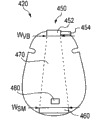
The working face up of substrate limits the work mounting s district of between vise assembly and work-supporting means, extending basically.Extend between these devices in the work mounting s district and width corresponds essentially to the width of these devices.Therefore, in the location that vise assembly is set of substrate, the width in work mounting s district is substantially equal to the width of vise assembly.This width is called W in this article
VBAnd shown in Fig. 2.Width W
VBUsually along the working face up of substrate with basic from this up the interface of working face between the vise assembly of upper process measure.And in the location that bracing or strutting arrangement is set of substrate, the width in work mounting s district is substantially equal to the width of supporting arrangement.This width is called W in this article
SMAnd shown in Fig. 2.This width W
SMBasically along the working face up of substrate and basically from this up the interface of working face between the supporting arrangement of upper process measure.The work mounting s district can be different or identical at the width at its two ends.This paper has provided other details and the aspect in work mounting s district.
As stated, known in the tube vice support---being specially in the substrate of these supports---is provided with one or more pipe bender.Typical pipe bender generally includes the workpiece hole of the crooked shaping piece and the correspondence of contiguous crooked shaping piece location.When managing when shaping piece is placed, the subregion of pipe extends through this hole.The pipe initial orientation becomes substantially, and vertical attitude extends through this bent hole simultaneously.Because this hole only is slightly larger than the overall diameter of pipe, therefore urge when managing when abutting against shaping piece, the part contact substrate that is positioned at the hole of pipe also is held fixing.Help like this operator to pipe be positioned at the part application of force above the shaping piece substantially the time, along the curved surfaces swan-neck of crooked shaping piece.Crooked shaping piece is from the form of the upwardly extending bent member of working face of substrate usually.Bent member limits the concave regions of the indent of extending around the arc of curvature that preferably limits around horizontal axis.The size of the concave regions of this indent and shaped design become receiving tube ordinatedly, preferably the pipe of acceptance criteria size.The exposed surface of this concave regions is for being shaped or curved surface.The pipe relevant with reception admitted in being dimensioned to of workpiece hole.Usually, crooked shaping piece in groups or become many covers to be provided with makes the pipe that can use the crooked a series of diameters of shaping piece, such as for example, and the pipe of 3/8 inch, 1/2 inch pipe, 5/8 inch, 3/4 inch and 1 inch.The typical pipe diameter combination that crooked shaping piece is suitable for is 1/2 inch, 3/4 inch and 1 inch.A plurality of canal curvature devices are commonly referred to " pipe bender " in the art.This paper discontinuous ground uses this term.The representative illustration of pipe bender for example is included at United States Patent (USP) 1,126, those pipe bendeies of mentioning in 544,1,393,766 and 2,831,583.
The substrate of the uniqueness of the tube vice support of preferred implementation adopts such configuration: at least a portion of a pipe bender or a plurality of pipe bendeies is positioned at the work mounting s district that limits along the working face of substrate.Preferably, a pipe bender or a plurality of pipe bender are positioned at the work mounting s district that is limited substrate fully.Have been found that these special configurations have obviously increased the available work area relevant with substrate, particularly particularly like this when supporting by the vise assembly joint and by work-supporting means such as workpiece such as pipes.Therefore, through using and/or adopting these special configurations, substrate can provide relatively large available work area when a lot of feature structures are provided equally, and the overall dimensions of substrate does not increase.In addition, another remarkable advantage that pipe bender is arranged in the middle section of substrate is and can applies bigger load or power to workpiece that engages with pipe bender or pipe, and do not influence the stability of support, helps carrying out bending like this.
Compare with the each side of vise assembly and work-supporting means, another feature of the tube vice support of preferred implementation described herein is to use the pipe bender that is no more than certain height.That is to say that pipe bender has maximum height and is set in place the specific location in the work mounting s district, thereby make them when managing by work-supporting means and vise assembly supporting and engaging, not interfere not contact tube.Tube vice support with preferred implementation is explained in more detail these aspects explicitly in this article.
Fig. 1 shows the tube vice support 10 according to the preferred implementation of the utility model.Support 10 comprises substrate 20, and substrate 20 limits roughly up working face 22, towards the neighboring 26 of opposite downside 24 and extension between working face 22 and downside 24.Substrate preferably includes basically along one or more shank holder 28 of the downside 24 of substrate 20.Substrate 20 also can further be limited with one or more hole 30 that at least partly extends through plate 20.Preferably perimeter or the edge 26 around substrate 20 also is limited with one or more notch 32.Substrate 20 also can comprise the upwardly extending flange that extends around the periphery of substrate 20 at least in part.
The tube vice support 10 of preferred implementation also comprises a plurality of shanks 40, and these a plurality of shanks 40 attach to substrate 20 movably and also preferably extend from the downside of substrate 20.Each shank 40 is limited with proximal end 44 and relative distal end 46.Proximal end 44 preferably engages with the corresponding shank holder 28 that is provided with along the downside of substrate 20 24.As point out that a plurality of shanks 40 preferably can position between such as extended position shown in Figure 1 and the retrieving position such as at delivery tube vice support the time.Support 10 also preferably includes and stretches bearing support 42, and this stretching, extension bearing support 42 attaches to the zone line of each shank 40 movably.After shank 40 was stretched over the position shown in Fig. 1, bearing support 42 was used to guarantee that shank 40 remains on this extended position, takes practical step that shank 40 is repositioned onto retrieving position until the operator.The utility model comprises having the almost tube vice support of the shank of any number.As stated, three shanks preferably.But, also comprise tube vice support with four shanks.And, if make it stable in a suitable manner, can expect that tube vice support as described herein can be provided with two shanks or single shank.Preferably be attached with chain 1 or other flexible member on one of them shank 40.After shank was positioned to retrieving position, chain 1 or flexible member can twine these shanks.
Tube vice support 10 also comprises and preferably is formed on the substrate 20 or additionally joins the vise assembly 50 on the substrate 20 to.Vise assembly comprises the vice base portion 52 on the workpiece composition surface 53 that is limited with up and is used to receive the handle base 54 of handle (not shown).Vise assembly 50 most preferably is arranged to the form of chain vices and is therefore comprised the chain (not shown).The details of the tube vice support and the chain vices in the substrate that are suitable for being combined in the utility model is provided with regard to current known chain vices; Current known chain vices have such as can be from the Ohio Ritchie Worktools Inc. in Illyria city (Ridge Tool of Elyria, the for example model of Ohio) buying is the chain vices of BC210, BC410, BC210P, BC410P, BC510, BC610, BC810, BC2A, BC4A and 640.Characteristic, structure, assembling, material, and the representative illustration aspect other of chain vices are provided in addition: 4,349,931,1,158,414,2,703,027 and 1,054,661 in one or more in following United States Patent (USP).Although chain vices preferably is combined in tube vice support described herein and/or the substrate; Perhaps use with tube vice support described herein and/or substrate; But should be appreciated that the vice that also can use other type, be such as but not limited to clamp-on pipe vise.
Fig. 2 to 4 illustrates in greater detail the substrate 20 of the tube vice support 10 of preferred implementation.Each pipe bender comprises crooked shaping piece or the concave regions 84 of bent member 82 and indent up.As shown in best among Fig. 2, be provided with workpiece hole 90 near the lowermost extent place of the concave regions 84 of crooked shaping piece 82.Being dimensioned to of each shaping piece 82, concave regions 84 and workpiece hole 90 closely receives and holds relevant pipe.More specifically, Fig. 4 shows the first pipe bender part of pipe bender 80, and first pipe bender partly limits concave regions 84a and corresponding workpiece hole 90a.Also show the second pipe bender part of pipe bender 80, second pipe bender partly limits concave regions 84b and corresponding hole 90b.And, showing the 3rd pipe bender part of pipe bender 80, the 3rd pipe bender partly limits concave regions 84c and corresponding hole 90c.As intelligible, the size of organizing each group in concave regions and the hole is preferably designed so that reception and holds relevant pipe more.
Further referring to Fig. 2 to 4, according to the utility model, preferably, at least a portion pipe bender 80 and preferably whole pipe bender 80 are arranged in the work mounting s district 70.In the specific embodiment that illustrates, pipe bender 80 is positioned at work mounting s district 70 fully.And pipe bender 80 is shown as along the width dimensions of substrate 20 placed in the middle basically in scope 70.In addition, for some embodiments, preferably, the maximum height of pipe bender 80 is equal to or less than the minimum constructive height of workpiece supporting member 60.The height of pipe bender 80 and workpiece supporting member 60 begins to measure from the working face 22 of substrate 20.For the specific embodiment of discussing, the maximum height that Fig. 3 illustrates pipe bender 80 is H
PBIn addition, the minimum constructive height of workpiece supporting member 60 also is shown is H to Fig. 3
SMTherefore preferably, the relative altitude of these parts is:
H
SM≥H
PB
Preferably, the maximum height of pipe bender 80 is equal to or less than the minimum constructive height of workpiece supporting member 60.In this preferred configuration, in the time of on workpiece or pipe being positioned at supporting member 60 and vise assembly, the upwardly extending pipe bender 80 that is positioned at the work mounting s district can not disturb workpiece, such as contact workpiece.
Yet, should be appreciated that the utility model is not limited to this preferred configuration.On the contrary, the utility model comprises such configuration: the maximum height of a pipe bender or a plurality of pipe bendeies can be greater than the minimum constructive height of workpiece supporting member.Generally,, a pipe bender or a plurality of pipe bender can have this configuration when departing from side direction with respect to the minimum constructive height position of workpiece supporting member or be spaced apart.Expect that also even for the such as shown in Figure 3 configuration that is positioned at the supporting member dead ahead of pipe bender, the maximum height of pipe bender also can be greater than the minimum constructive height of supporting member.When using supporting member to come support column or other column, allow this configuration.Because supporting member as shown in Figure 3 has the V-arrangement profile, therefore when pipe being placed in the V-arrangement supporting member, the minimum surface of pipe will be opened in that the minimum constructive height of supporting member is spaced above.Therefore, the maximum height of pipe bender can be extended in the scope between the minimum constructive height of minimum tube-surface and supporting member.Yet; Generally; When height in supporting member the time, at height of measuring pipe bender along the position of the line that is parallel to pipe or other member and workpiece supporting member of pipe or other member supporting, the height of pipe bender is less than or equal to the height of workpiece supporting member.
Be appreciated that the utility model is in no way limited to the substrate with particular configuration, shape and/or layout shown in Fig. 2 to 4.The utility model also is not limited to parts or the device shown in accompanying drawing.Therefore, the substrate that can expect the utility model can adopt has the vice board structure that is different from shape shown in Fig. 2 to 4 and/or configuration.Similarly, the substrate of the utility model can use shape, type and configuration to be different from the workpiece supporting member of supporting member shown in Fig. 2 to 4 60.Equally, the utility model comprises the pipe bender that shape, type and configuration are different.
The utility model comprises a large amount of different configuration and the configuration of substrate, is specially the relative position of vise assembly, workpiece supporting member and pipe bender.For example, Fig. 5 to 8 is the schematic plan according to another preferred implementation substrate of the utility model.Fig. 5 shows a kind of substrate 120 that comprises the preferred implementation of vise assembly 150 and workpiece supporting member 160.Work mounting s district 170 is limited between the vice base portion 152 and workpiece supporting member 160 of vise assembly 150.In work mounting s district 170, be provided with one or more pipe bender 180.Be appreciated that in this embodiment vise assembly 150 is not placed in the middle along the central axis of substrate as in the substrate 20 of Fig. 1 to 4, but be provided with along the turning or the lateral edge zone of substrate 120.Handle base 154 can and be not limited to the certain orientation shown in Fig. 5 according to expectation set.The orientation of workpiece supporting member 160 can be oriented in the face of the vice base portion 152 shown in Fig. 5.
Fig. 6 shows another preferred implementation substrate 220 again according to the utility model.Substrate 220 comprises vise assembly 250 and workpiece supporting member 260, and vise assembly 250 and workpiece supporting member 260 limit the work mounting s district 270 of between them, extending.As intelligible, vise assembly 250 comprises vice base portion 252 and handle base 254.Substrate 220 further comprises one or more pipe bender 280 that is arranged in the work mounting s district 270.In Fig. 6, the lateral region setting of workpiece supporting member 260 on the side direction of substrate 220, rather than the longitudinal axis along substrate is placed in the middle shown in Fig. 1 to 4.Equally, workpiece supporting member 260 can be oriented in the face of vice base portion 252.
Fig. 7 shows the another preferred implementation substrate 320 according to the utility model.Substrate 320 comprises vise assembly 350 and workpiece supporting member 360, and vise assembly 350 and workpiece supporting member 360 limit the work mounting s district 370 of between them, extending.Vise assembly 350 comprises vice base portion 352 and handle base 354.Substrate 320 also comprises one or more pipe bender 380 that is arranged in the supporting area 370.The substrate 320 of Fig. 7 is characterised in that to have the workpiece supporting member 360 and vise assembly 350 that is provided with along the relative lateral region of the cardinal principle of substrate 320.In embodiment, pipe bender 380 is medially located between vise assembly 350 and workpiece supporting member 360 basically.
Fig. 8 shows the substrate 420 according to the another preferred implementation of the utility model.Under this form of the utility model, substrate 420 comprises vise assembly 450 and workpiece supporting member 460, yet vise assembly 450 but is arranged on the opposite end with workpiece supporting member 460 opposite each other comparing with the substrate 20 that combines Fig. 1 to 4 to describe.As understandable, vise assembly 450 comprises vice base portion 452 and handle base 454.Substrate 420 comprises one or more pipe bender 480 that is arranged in the work mounting s district 470, and wherein extend between vise assembly 450 and workpiece supporting member 460 in this work mounting s district 470.
Be appreciated that the utility model comprises the modification of all deposition profile shown in Fig. 5 to 8.Therefore for example, referring to Fig. 5, vice base portion 152 can be provided with along the right side of substrate 12, rather than the left side that is arranged on as shown in the figure.Similarly, in Fig. 6, vice base portion 252 can be arranged on the right side of substrate 220, and workpiece supporting member 260 is arranged on the left side of substrate 220.Configuration for shown in Fig. 7 and 8 can be expected similar modification.
In addition, be appreciated that the utility model is not receiving any restriction such as 154 handle base on respect to the orientation of corresponding vice base portion 152 and/or position.For example referring to Fig. 5, extend although handle base is shown as from the specific region of vice base portion 152, the utility model comprises the alternative arrangements of handle with respect to corresponding vice base portion.
As stated, said one or more pipe bender can fully or only partly be positioned in the work mounting s district.Earlier figures 1 to 8 shows the multiple preferred implementation of substrate, and wherein their corresponding pipe bendeies are positioned in the supporting area fully.Fig. 9 to 12 shows multiple preferable substrate, and wherein their corresponding pipe bendeies only partly are positioned in the supporting area.For example, Fig. 9 shows a kind of substrate 520 of preferred implementation, and this substrate 520 comprises vise assembly 550, workpiece supporting member 560 and the work mounting s district 570 of between vise assembly 550 and workpiece supporting member 560, extending.Vise assembly 550 comprises vice base portion 552 and handle base 554.Substrate 520 also comprises one or more pipe bender 580 that is positioned partially in the supporting area 570.Because pipe bender 580 is positioned partially in the supporting area 570, so the part of pipe bender 580 is positioned at outside the supporting area.
Figure 10 shows the substrate 620 of another preferred implementation, and this substrate 620 comprises vise assembly 650, workpiece supporting member 660 and the work mounting s district 670 of between vise assembly 650 and workpiece supporting member 660, extending.Vise assembly 650 comprises vice base portion 652 and handle base 654.Substrate 620 also comprises one or more pipe bender 680 that partly is arranged in the supporting area 670.Under this form, pipe bender 680 is nearer apart from supporting member 660 apart from vise assembly 650 ratios.
Figure 11 shows the substrate 720 according to the another preferred implementation of the utility model.This substrate 720 comprises vise assembly 750, workpiece supporting member 760 and the work mounting s district 770 of between vise assembly 750 and workpiece supporting member 760, extending.As intelligible, vise assembly 750 comprises vice base portion 752 and handle base 754 spaced away.Substrate 720 also comprises one or more pipe bender 780 that is at least partially disposed in the supporting area 770.In this embodiment, please note that vise assembly 750 and workpiece supporting member 760 one or both of can be towards the interior zone location of substrate 720 and spaced apart with the outward flange of substrate 720.
In addition, Figure 12 shows the substrate 820 according to the another preferred implementation of the utility model.This substrate 820 comprises vise assembly 850 and workpiece supporting member 860.Vise assembly 850 comprises vice base portion 852 and handle base 854.Substrate is limited with the work mounting s district 870 of between vise assembly and supporting member 860, extending.In this embodiment, one or more pipe bender 880 only partly is arranged in the supporting area.In this embodiment, pipe bender 880 is arranged in the corner region of substrate 820 near vice base portion 852.
The utility model also comprises following embodiment: one or more pipe bender setting or be positioned to and open along the location interval at the shank of substrate downside place.Although a plurality of embodiments shown in Fig. 5 to 12 have embodied this configuration, following further explanation is provided still.In this configuration, what one or more pipe bender was arranged on substrate is not arranged in the zone directly over the shank holder---shank holder 28 as shown in Figure 1---.For example, expected that the edge notch 32 that one or more pipe bender can be close to or be close to shown in Fig. 1 to 2 and Fig. 4 is provided with.Preferably, at least a portion of pipe bender (not being placed in shank holder top) extends in the work mounting s district as described herein.In these preferred configuration above pipe bender is not placed in the shank holder, pipe bender preferably aligns with shank and/or shank holder along the opposed area setting on the opposite of substrate.
In all embodiments that combine Fig. 5 to 12 to describe, that is, in substrate 120,220,320,420,520,620,720 and 820, substrate is limited with the work mounting s district, that is, and and 170,270,370,470,570,670,770 and 870.As point out that each work mounting s district extends between vise assembly and workpiece supporting member, preferably between the vice base portion of vise assembly and workpiece supporting member, extend.As the description that combines Fig. 1 to 4 points out that supporting area can be a lot of different form, shape and size.Supporting area can differ from one another or identical at the width of each end.Therefore, supporting area can be corresponding to situation (i) any one in (iii):
(i) W
VB=W
SM;
(ii) W
VB>W
SMPerhaps
(iii) W
VB<W
SM
The utility model comprises that also substrate does not comprise the embodiment of workpiece supporting member.Although this embodiment is preferred not as embodiment described herein, the utility model does not comprise not the substrate such as 160,260,360,460,560,660,760 and 860 class A of geometric unitA.In these not too preferred configurations, the work mounting s district projects to the opposite through the width with vise assembly and limits on the surface up of substrate.Orientation when being arranged essentially parallel to such as the member of managing in being anchored on vise assembly is got projection line.In addition, should be appreciated that the utility model comprises the substrate with polytype vice.The utility model is in no way limited to have the substrate of chain vices.The non-limiting example of vice comprises chain vices, clamp-on pipe vise, vice chuck or drill bit vice, compound rest vice, eccentric vice, oblique vice, sinusoidal vice, swivel vise, molding vice and needle pliering.
In addition, it will also be appreciated that the utility model comprises the workpiece supporting member arrangement or is arranged on the embodiment between pipe bender and the vise assembly.In these optional configurations, pipe bender is settled and workpiece supporting member is at least partially disposed between pipe bender and the vise assembly along the peripheral edge regions of substrate.Therefore, workpiece supporting member is arranged on the pipe bender inboard, and pipe bender is arranged on the workpiece supporting member outside in other words.Figure 22 shows the example of this alternate configuration of the embodiment that combines Fig. 2 description.
In some embodiments, working face from substrate (working face of next-door neighbour's substrate is measured) can preferably be set with angle less than 90 °---for example, from about 60 ° to about 30 °, and most preferably about 45 °---upwardly extending pipe bender.This configuration of pipe bender can help bending operation, thereby because make pipe from the upwardly extending part of substrate not directly over substrate the operator approaching more easily.Referring to Figure 13 and 14, show another representative preferable substrate 920.Substrate 920 comprises vise assembly 950, and vise assembly 950 comprises vice base portion 952 and handle base 954.One or more workpiece supporting member 960 relatively is provided with vise assembly 950 basically.Like what describe in the text before, between vise assembly 950 and supporting member 960, limit work mounting s district 970.Substrate 920 also comprises the pipe bender 980 that is at least partially disposed in the supporting area 970.Pipe bender 980 comprises the crooked shaping piece 982 up of the concave regions 984 that limits indent.Be shaped or curved surface extends upward with angle A from the working face of substrate 920, this angle A is from about 60 ° to about 30 °, and is preferably about 45 °.Between the lowermost extent of the contiguous working face of the curved surface of the working face of substrate and shaping piece, measure angle A.Although the utility model is not limited to any ad-hoc location of pipe bender, as long as pipe bender is positioned at the work mounting s district at least in part, preferably with pipe bender be positioned on the downside of substrate attached or joint have shank the position directly over.
In some embodiments, possibly preferably include the leveling apparatus that one or more is used for the vice support.Leveling apparatus makes the operator can regulate the direction of substrate.Preferably, with a shank leveling apparatus is set explicitly explicitly and most preferably with at least one shank.It will also be appreciated that, can both comprise leveling apparatus on each shank.As described herein, most preferably, leveling apparatus makes the operator be in load following time at support---such as at holding workpieces the time and/or such as apply by the screw thread jack steady load during---regulate the direction of substrate.
Can use multiple different assembly and the tactful smoothing that realizes the vice support of the utility model.For example, leveling apparatus can be the form of threaded leg member, so that the rotation of leg member causes leg member to extend point-blank or withdraw along its longitudinal axis.Another form of leveling apparatus is to use the screw member on the distal end that is arranged on shank.The adjustable range of leveling apparatus preferably make the direction of substrate can change at least+/-3 °.Yet the utility model comprises following form: the direction of substrate can change to a greater degree, such as changing at least+/-5 ° or bigger.
Leveling apparatus can comprise that thick smoothing is regulated and smart smoothing is regulated.For example, coarse adjustment can be the form of the leg segment of intussusception, and these leg segment are bonded with each other through the member that is inserted in the mating holes that in these leg segment, forms.In each leg segment, preferably form a plurality of holes.A leg segment suitably being positioned another leg segment and corresponding paired hole on time, said member is inserted in the hole of aligning, thereby leg segment is joined to together with the leg length of expectation.
Smart leveling apparatus can be provided by the screw member on the distal end that is arranged on shank.Similarly, depend on thread characteristics and flight pitch, what also can the length along shank or leg segment partly be combined with threaded portion is configured to smart leveling apparatus or thick leveling apparatus.
Can comprise optional locking device relatively with leveling apparatus.Locking device can be a variety of forms, engages locking component, lock nut etc. such as screw thread.
Figure 15 schematically shows the leveling apparatus 1010 of preferred implementation, and this leveling apparatus 1010 is provided with the shank 1040 of vice support---such as the vice support 10 shown in Fig. 1---explicitly.Shank 1040 is limited with distal end 1042 and proximal end (not shown), and shank 1040 is attached to or is engaged to the substrate (not shown) at this proximal end place.Leveling apparatus 1010 preferably is positioned between the distal end and proximal end of shank 1040; And under this form, leveling apparatus 1010 comprises first screw member 1044 that engages with the proximal part of shank and the second corresponding screw member 1046 that engages with these first screw member, 1044 screw threads.Second screw member 1046 is engaged to the distal portions of shank 1040.Should be appreciated that the distal end 1042 of shank 1040 is shifted along the longitudinal axis of first screw member 1044 and shank 1040 point-blank when rotation second member 1046.Preferably, be provided with key apparatus explicitly, so that after locating distal end 1042 ideally, prevent of the longitudinal axis rotation of this end around shank 1040 with distal end 1042.In preferred configuration, leg portion 1041 was to catch leg portion 1041 and this part 1041 is attached to shank 1040 under screw member 1046 engaged.
The shank leveling apparatus 1110 of the another embodiment that Figure 16 has schematically described to be provided with explicitly with shank 1140.Leveling apparatus 1110 is preferably located near the distal end 1142 of shank 1140.Device 1110 comprises screw member 1144, and this screw member 1144 has the head 1146 that is suitable for engaging with spanner and relative foot 1148.Member 1144 extends through the distal end 1142 of shank 1140 and engages with engage thread with this distal end 1142.Should be appreciated that when member 1144 rotation, can regulate the air line distance between the distal end 1142 of foot 1148 and shank 1140.
Figure 17 schematically shows another leveling apparatus 1210 and is attached to the situation in the distal end 1242 of shank 1240.Leveling apparatus 1210 comprises the screw member 1244 with head 1246 and foot 1248.Screw thread foot liner 1250 is arranged in the hole that limits in the shank distal end 1242.When the desired locations that member 1244 is optionally rotated to respect to the distal end 1242 of shank 1240, can enough lock nut 1255 member 1244 be fastened on the position of this expectation.
Figure 18 schematically shows another leveling apparatus 1310, and this leveling apparatus 1310 is provided with one or more shank 1340 of vice support (not shown) explicitly.Each shank 1340 is limited with proximal end 1341 and distal end 1342.Leveling apparatus 1310 is arranged between end 1341 and 1342.In this mode, be limited with a plurality of holes 1305 along the part of far-end leg segment, and in the near-end leg segment, be limited with at least one hole 1308.Leg segment preferably can telescopically engage each other.,, with retaining member or sell (not shown) and be inserted in the hole of this aligning thereby leg segment is fastened to together with after 1308 each other aim in hole 1305.
Should be appreciated that, arbitrary described leveling apparatus can both use with other leveling apparatus and can use vice support as herein described more than one shank in.That is, the utility model is limited to arbitrary concrete leveling apparatus as herein described absolutely not.
Figure 19 is the detail view of the fastening assembly 101 of preferred implementation, and this fastening assembly 101 combines the support setting of preferred implementation.Fastening assembly 101 generally includes first retaining member 102, one section chain 104 or similarly member and button 106 with closing device.Preferably, retaining member 102 centers on shank---such as shank 40 of the support shown in Fig. 1 10---extension of support and most preferably is attached to this shank.Retaining member 102 preferably is positioned adjacent to the distal end of shank 40, such as end 46, but the utility model is not limited to this configuration.Preferably, the end 104a of chain 104 is attached to retaining member 102.Opposite ends 104b is freely.Button 106 preferably includes abutting end 106a and relatively large fastening area 106c, and button 106 engages with retaining member 102 at this abutting end 106a place.Button 106 preferably includes connecting elements 106b, and this connecting elements 106b removably is fastened to fastening area 106c along linkage interface 106d.Typically, and after being positioned at the support (not shown) in the retrieving position, chain 104 holds other shank (not shown).The free end 104b of chain 104 is fastened to button 106, and preferably detains 106 through connecting elements 106b is come to be fastened at linkage interface 106d place and fastening area 106c branch.
Should be appreciated that and to detain in the end open link 104b that 106 connecting elements 106b or fastening area 106c be inserted into chain 104.Make connecting elements 106b be engaged in fastening area 106c then, thereby the terminal 104b of chain 104 is attached to button 106 with " closure " button 106.Be appreciated that various other fastening with keep assembly can be used to buckle 106 and/or chain 104.Non-limiting example comprises cable, rope, rope, band and flexible member.
Figure 20 and 21 shows the leg assembly 1410 of the preferred implementation of in vice support described herein, using.Leg assembly 1410 comprises leg portion 1440, following leg portion 1441 and the adjusting device between last leg portion 1440 and following leg portion 1441, and this adjusting device is used to connect two leg portions and the leg portions location of optionally regulating relative to each other is provided.Following leg portion 1441 is limited with preferably distal end or the foot 1442 integrally formed with following leg portion 1441.Adjusting device preferably includes the member 1446 that rotatably attaches to down leg portion 1441.Member 1446 is limited with the central, threaded hole, and this screwed hole receives screw member 1444 or the screw thread extension of going up leg portion 1440.As understandable, when member 1446 and member 1444 engage with engage thread and during rotating member 1446, can be optionally and change the air line distance that goes up between leg portion 1440 and the following leg portion 1441 with the mode that increases.
Preferably, all be provided with key apparatus in the leg portion up and down.Key apparatus prevent down leg portion 1441 with respect to last leg portion 1440 around the rotation of its longitudinal axis, and reverse situation.Although can use multiple key apparatus, preferred configuration has been shown among Figure 20.The edge end of leg portion 1441 down is provided with the channel region 1430 that extends internally.In screw member 144, be provided with slotted recess or hole 1445.Slotted recess or hole 1445 be dimensioned to the channel region 1430 that reception slidably extends internally.This configuration allows leg portions 1441 and 1440 longitudinal axis along them relative to each other to be shifted point-blank, but prevents that one of them from rotating around longitudinal axis with respect to another.
Figure 21 shows preferred configuration and the joint between the parts.Member 1446 is limited with and a pair ofly extends laterally handle or handle 1452 and 1452 ' from what central body 1456 was extended in opposite direction.Member 1446 is limited with from first opening 1454 and extends through the screwed hole that body 1456 arrives towards the second opposite opening 1457.The end of leg portion 1441 is down rotatably held in being dimensioned to of second opening 1457.This end of following leg portion 1441 preferably includes outward extending disc-shaped component 1420.Member 1446 is limited with can be from the approaching interior hollow region 1450 of opening 1457.Being dimensioned to of this hollow region 1450 rotatably receives disc element 1420.Therefore, through this configuration, member 1446 can two pin components securely be linked together situation under, with respect to down leg portion 1441 and disc element 1420 rotations.
Each parts of vice support described herein can be formed by the material that almost is fit to arbitrarily, and this material has intensity enough for support, durability and rigidity so that kind as described herein plays a role.The preferred metal such as the hardened steel of different brackets.Also expect other metal such as the alloy of aluminium, magnesium etc.The preferred material that is used for substrate is an aluminium.Expect that further composite can be used for some parts.The utility model is not limited to any specific material type.
Characteristic, structure, assembling, material, and the representative illustration aspect other of vice support and tube vice support are provided: 1,634,837,798,371,1,216 in one or more in following United States Patent (USP); 610,4,715,760,1,686,023,1; 393,766,1,126,544,4; 231,557 and 7,430,968.In addition, in U.S. Patent application open source literature US2007/0080268, also mention these information.
From the application in future and development of this technology, much other advantage will undoubtedly become obvious.
Whole disclosures of all patents that this paper mentions, disclosed application documents and article are all incorporated through reference in view of the above.
Any or the more a plurality of characteristic or the parts that it should be understood that a certain embodiment as herein described can combine with one or more characteristic or the parts of another embodiment.Therefore, the utility model comprises parts or any of characteristic or whole combinations of embodiment as herein described.
As indicated above, the utility model has solved the device-dependent a plurality of problems with aforementioned type.But; Should be appreciated that; Those skilled in the art can be to having described in the literary composition and explained with details, material and the arrangements of components of explaining the utility model character and carry out multiple variation, and can not depart from principle and the scope of liking the utility model described in the claim enclosed.
Claims (25)
1. a tube vice support is characterized in that, said tube vice support comprises:
Substrate; Said substrate is limited with working face; And comprise at least one supporting arrangement of extending from said working face and with the isolated vise assembly of said at least one supporting arrangement, said substrate further is limited with along the said working face and the work mounting s district of between said at least one supporting arrangement and said vise assembly, extending; And
A plurality of shanks, said a plurality of shanks are attached to said substrate;
Wherein, said substrate further comprises at least one pipe bender, and said at least one pipe bender is at least partially disposed in the said work mounting s district.
2. tube vice support as claimed in claim 1 is characterized in that, said at least one pipe bender is arranged in the said work mounting s district fully.
3. tube vice support as claimed in claim 1 is characterized in that, said at least one pipe bender comprises three pipe shaping pieces.
4. tube vice support as claimed in claim 3 is characterized in that, whole three pipe shaping pieces all are arranged in the said work mounting s district.
5. tube vice support as claimed in claim 1 is characterized in that, said at least one pipe bender comprises the hole that is limited in the said substrate, and said hole is positioned at said work mounting s district.
6. tube vice support as claimed in claim 1 is characterized in that the maximum height of said at least one pipe bender is less than the minimum constructive height of said at least one supporting arrangement.
7. tube vice support as claimed in claim 1 is characterized in that, said tube vice support also comprise with said a plurality of shanks at least one leveling apparatus that is associated.
8. tube vice support as claimed in claim 1 is characterized in that said tube vice support also comprises the fastening assembly of the shank that is attached to said support, and said fastening assembly comprises: retaining member, and said retaining member extends around said shank; Chain segment, an end of said chain segment is attached to said retaining member; And button, said button engages with said retaining member and has closing device, and said closing device makes it possible to optionally said button engaged with said chain segment.
9. a tube vice support is characterized in that, said tube vice support comprises:
Substrate; And
A plurality of extensile shanks, said a plurality of extensile shanks are attached to said substrate movably, and each shank is limited with the proximal end that attaches to said substrate and the distal end relative with said proximal end;
Said vice support can be located between following configuration: (i) work configuration, and under said work configuration, said a plurality of shanks extend to extended position from said substrate, and the said distal end of said shank is in the same plane; And (ii) transport configuration, under said transportation configuration, said shank is regained from their extended position;
Said substrate is limited with working face, when said vice support is in the said distal end exposure level surface of work configuration and said shank, said working face up, said substrate comprises:
The vise assembly at the primary importance place of said substrate on the edge;
The supporting arrangement at the second place place of said substrate on the edge, said supporting arrangement and said vise assembly are relatively also spaced apart; And
At least one crooked shaping piece from said substrate extension;
Wherein, said substrate is limited with work mounting s district working face, that between said vise assembly and said supporting arrangement, extend along said substrate, and said at least one crooked shaping piece is positioned in the said work mounting s district at least in part.
10. tube vice support as claimed in claim 9 is characterized in that, said at least one crooked shaping piece is positioned at said work mounting s district fully.
11. tube vice support as claimed in claim 9 is characterized in that, said at least one crooked shaping piece comprises three crooked shaping pieces altogether.
12. tube vice support as claimed in claim 11 is characterized in that, whole three said crooked shaping pieces all are positioned at said work mounting s district.
13. tube vice support as claimed in claim 9; It is characterized in that; Said substrate limits at least one hole of contiguous said at least one crooked shaping piece, and the size in said hole is designed to receive by said crooked shaping piece with structure carries out crooked pipe or tube.
14. tube vice support as claimed in claim 13 is characterized in that, said at least one hole also is positioned in the said work mounting s district at least in part.
15. tube vice support as claimed in claim 13 is characterized in that, said at least one hole is positioned in the said work mounting s district fully.
16. tube vice support as claimed in claim 9 is characterized in that, said vise assembly comprises the chain vices of optionally regulating.
17. tube vice support as claimed in claim 9 is characterized in that, said tube vice support also comprises:
The screw thread jack, said screw thread jack is suitable for optionally engaging fixedly rigid member, and when said screw thread jack abuts against the elongation of said member, on said tube vice support, applies load down, improves the stability of said support thus.
18. tube vice support as claimed in claim 9 is characterized in that the maximum height of said at least one crooked shaping piece is less than the minimum constructive height of said supporting arrangement.
19. tube vice support as claimed in claim 9 is characterized in that, said tube vice support also comprise with said a plurality of shanks at least one leveling apparatus that is associated.
20. tube vice support as claimed in claim 9 is characterized in that said tube vice support also comprises the fastening assembly of the shank that is attached to said support, said fastening assembly comprises: retaining member, and said retaining member extends around said shank; Chain segment, an end of said chain segment is attached to said retaining member; And button, said button engages with said retaining member and has closing device, and said closing device makes it possible to optionally said button engaged with said chain segment.
21. one kind is used for the substrate that uses with the tube vice support; It is characterized in that; The said substrate of said tube vice support is limited with working face, towards the opposite downside and the peripheral edge regions of between said working face and said downside, extending, said substrate comprises:
At least one supporting arrangement, said at least one supporting arrangement extends beyond said working face from said substrate, and said at least one supporting arrangement limits first width dimensions;
Vise assembly, said vise assembly extends from said substrate, and said vise assembly limits second width dimensions, and said vise assembly and said at least one supporting arrangement are spaced apart;
Wherein, said substrate further is limited with along work mounting s district said working face, that between said first width and said second width, extend;
Said substrate further comprises the pipe bender that is arranged in the said work mounting s district.
22. substrate as claimed in claim 21 is characterized in that, said pipe bender comprises the device of the pipe that is used for crooked at least two kinds of different-diameters.
23. substrate as claimed in claim 21 is characterized in that, said vise assembly comprises chain vices.
24. substrate as claimed in claim 21 is characterized in that, said at least one supporting arrangement is limited with V-arrangement indent zone up.
25. substrate as claimed in claim 21 is characterized in that, the maximum height of said pipe bender is less than the minimum constructive height of said at least one supporting arrangement.
Applications Claiming Priority (2)
| Application Number | Priority Date | Filing Date | Title |
|---|---|---|---|
| US13/005,032 | 2011-01-12 | ||
| US13/005,032 US8967606B2 (en) | 2011-01-12 | 2011-01-12 | Pipe vise stand |
Publications (1)
| Publication Number | Publication Date |
|---|---|
| CN202491234U true CN202491234U (en) | 2012-10-17 |
Family
ID=46454181
Family Applications (2)
| Application Number | Title | Priority Date | Filing Date |
|---|---|---|---|
| CN201110253533.7A Expired - Fee Related CN102581831B (en) | 2011-01-12 | 2011-08-26 | Pipe vise stand |
| CN 201120321189 Expired - Lifetime CN202491234U (en) | 2011-01-12 | 2011-08-26 | Tube vice support and substrate used together with tube vice support |
Family Applications Before (1)
| Application Number | Title | Priority Date | Filing Date |
|---|---|---|---|
| CN201110253533.7A Expired - Fee Related CN102581831B (en) | 2011-01-12 | 2011-08-26 | Pipe vise stand |
Country Status (4)
| Country | Link |
|---|---|
| US (1) | US8967606B2 (en) |
| CN (2) | CN102581831B (en) |
| CA (1) | CA2763518A1 (en) |
| DE (1) | DE102012000164A1 (en) |
Families Citing this family (10)
| Publication number | Priority date | Publication date | Assignee | Title |
|---|---|---|---|---|
| US10105834B2 (en) * | 2015-11-09 | 2018-10-23 | Ridge Tool Company | Adapters for chain pipe vises |
| US10632592B2 (en) * | 2017-01-11 | 2020-04-28 | Jpw Industries Inc. | Quick clamp pipe vise and method |
| EP3762182B1 (en) * | 2018-03-09 | 2024-04-24 | Milwaukee Electric Tool Corporation | Pipe fitting stand |
| US11850724B2 (en) | 2018-03-09 | 2023-12-26 | Milwaukee Electric Tool Corporation | Pipe fitting stand |
| CN108908230A (en) * | 2018-04-27 | 2018-11-30 | 盐城易快来科技有限公司 | A kind of high-definition display screen device for detecting performance and detection method |
| CN219255500U (en) | 2020-02-10 | 2023-06-27 | 米沃奇电动工具公司 | Pipe fitting support for supporting pipe during working operation |
| CN111702057B (en) * | 2020-06-24 | 2022-03-29 | 瓯锟科技温州有限公司 | High-precision trimming device for metal composite plate |
| US12515299B2 (en) * | 2020-07-29 | 2026-01-06 | Lego A/S | Alignment jig and holding system for a workpiece |
| CN115889952A (en) * | 2022-12-08 | 2023-04-04 | 中国航发贵州黎阳航空动力有限公司 | Automatic argon arc welding clamping positioning fixture and method for pipe wrench |
| USD1077646S1 (en) * | 2024-12-10 | 2025-06-03 | Liangliang Zhang | Storage tray |
Family Cites Families (56)
| Publication number | Priority date | Publication date | Assignee | Title |
|---|---|---|---|---|
| US1726898A (en) * | 1929-09-03 | Workbench | ||
| US2733330A (en) | 1956-01-31 | blewett | ||
| US798371A (en) | 1905-05-10 | 1905-08-29 | D E Morris | Vise-mount. |
| US1158414A (en) | 1911-12-27 | 1915-10-26 | Williams J H & Co | Chain pipe-vise. |
| US1054661A (en) | 1911-12-27 | 1913-03-04 | Williams J H & Co | Chain pipe-vise. |
| US1040603A (en) * | 1911-12-27 | 1912-10-08 | Williams J H & Co | Chain pipe-vise or the like. |
| US1126544A (en) * | 1914-05-11 | 1915-01-26 | Clarence Frank Martin | Work-stand. |
| US1184991A (en) | 1915-09-24 | 1916-05-30 | Ernest H Pettit | Pipe-gripping attachment for vises. |
| US1216610A (en) | 1916-07-20 | 1917-02-20 | Harry Rosenbaum | Portable work-bench. |
| US1393766A (en) | 1920-04-29 | 1921-10-18 | Charme William S Du | Portable pipe-vise stand |
| US1686023A (en) * | 1923-11-22 | 1928-10-02 | Mccloskey Leo | Pipe vise and stand |
| US1653326A (en) | 1925-04-23 | 1927-12-20 | Armstrong Bros Tool Co | Chain pipe vise |
| US1695311A (en) | 1925-09-23 | 1928-12-18 | Western Wire Products Company | Pipe-vise stand |
| US1798340A (en) * | 1926-10-09 | 1931-03-31 | Ridge Tool Co | Vise stand |
| US1634837A (en) | 1927-01-07 | 1927-07-05 | Nye Tool & Machine Works | Vise stand |
| US1785884A (en) * | 1927-10-03 | 1930-12-23 | Toledo Pipe Threading Machine | Pipe vise |
| US1784264A (en) * | 1928-06-13 | 1930-12-09 | Western Wire Products Co | Pipe-vise stand |
| US1812967A (en) * | 1929-11-27 | 1931-07-07 | Penn Engineering Company | Vise stand |
| US1897449A (en) | 1932-01-08 | 1933-02-14 | Frederick A Trowbridge | Portable and adjustable vise-stand |
| US2191191A (en) | 1939-01-18 | 1940-02-20 | Beaver Pipe Tools Inc | Power unit |
| US2297980A (en) | 1940-10-16 | 1942-10-06 | Ralph I Perkins | Folding vise stand |
| US2310255A (en) * | 1941-04-07 | 1943-02-09 | Maurice M O'connell | Pipe handling equipment |
| US2666609A (en) | 1948-08-19 | 1954-01-19 | Ridge Tool Co | Tool supporting tray |
| US2703027A (en) * | 1952-12-10 | 1955-03-01 | Reed Mfg Co | Pipe vise |
| US2678790A (en) * | 1953-05-29 | 1954-05-18 | Egger Crawford | Tilting top folding pipe vise stand |
| US2831583A (en) * | 1954-06-30 | 1958-04-22 | Ridge Tool Co | Vise stand |
| US2883184A (en) * | 1956-11-01 | 1959-04-21 | Philip J Brewington | Plumber's work table |
| US2978114A (en) | 1959-02-09 | 1961-04-04 | Nye Tool Company | Folding tripod with folding platform |
| US3656439A (en) | 1969-10-09 | 1972-04-18 | Bremshey & Co | Tilting table |
| US4083624A (en) | 1977-01-19 | 1978-04-11 | Henry Timmer | Terminal clamp |
| US4133519A (en) | 1977-01-24 | 1979-01-09 | Kyoung-Ho Shin | Vise with selectable jaw faces |
| US4231557A (en) | 1979-02-21 | 1980-11-04 | Emerson Electric Co. | Portable work bench |
| US4210373A (en) | 1979-05-21 | 1980-07-01 | Mcgee Norris E | Ground clamp for welding apparatus |
| US4349931A (en) * | 1980-05-27 | 1982-09-21 | Leon Harry I | Threading die couple |
| US4715760A (en) | 1986-10-22 | 1987-12-29 | Browning Ervin R | Hoist for installing cabinets, ceiling frames and the like |
| US5135208A (en) * | 1990-10-09 | 1992-08-04 | Coors Brewing Company | Chain guide apparatus for a pipe vise |
| US6089554A (en) * | 1997-09-16 | 2000-07-18 | Berardino; John | Portable work platform |
| US6073919A (en) * | 1999-05-28 | 2000-06-13 | Hammit; Floyd E. | Stand for chain vise |
| US6471220B1 (en) | 2000-06-13 | 2002-10-29 | Emerson Electric Co. | Cart and stand for supporting and transporting metal working apparatus |
| US7537186B2 (en) * | 2004-08-19 | 2009-05-26 | Emerson Electric Co. | Work stand |
| US20070080268A1 (en) | 2005-10-07 | 2007-04-12 | Derek Worrell | Hawk stand and accessory holder |
| US7430968B2 (en) | 2005-10-11 | 2008-10-07 | Clark Roger T | Folding work platform |
| US20080029662A1 (en) | 2006-08-03 | 2008-02-07 | O'rourke John F | Tool holder attachment for rigid pipe tristand |
| US7992852B2 (en) * | 2008-02-04 | 2011-08-09 | Milwaukee Electric Tool Corporation | Pipe stand with accessories |
| USD645326S1 (en) * | 2011-01-12 | 2011-09-20 | Emerson Electric Co. | Base plate |
| USD645320S1 (en) * | 2011-01-12 | 2011-09-20 | Emerson Electric Co. | Base plate |
| USD645319S1 (en) * | 2011-01-12 | 2011-09-20 | Emerson Electric Co. | Base plate |
| USD645325S1 (en) * | 2011-01-12 | 2011-09-20 | Emerson Electric Co. | Base plate |
| USD645322S1 (en) * | 2011-01-12 | 2011-09-20 | Emerson Electric Co. | Base plate |
| USD645323S1 (en) * | 2011-01-12 | 2011-09-20 | Emerson Electric Co. | Base plate |
| USD645327S1 (en) * | 2011-01-12 | 2011-09-20 | Emerson Electric Co. | Base plate |
| US8727330B2 (en) * | 2011-01-12 | 2014-05-20 | Emerson Electric Co. | Grounding component for electric welding systems and methods |
| US8777205B2 (en) * | 2011-01-12 | 2014-07-15 | Emerson Electric Co. | Pipe vise stands and components for increasing capacity thereof |
| USD645324S1 (en) * | 2011-01-12 | 2011-09-20 | Emerson Electric Co. | Base plate |
| USD645321S1 (en) * | 2011-01-12 | 2011-09-20 | Emerson Electric Co. | Base plate |
| US8601855B1 (en) * | 2012-06-13 | 2013-12-10 | Emerson Electric Co. | Vise apparatus with a bending fixture |
-
2011
- 2011-01-12 US US13/005,032 patent/US8967606B2/en active Active
- 2011-08-26 CN CN201110253533.7A patent/CN102581831B/en not_active Expired - Fee Related
- 2011-08-26 CN CN 201120321189 patent/CN202491234U/en not_active Expired - Lifetime
-
2012
- 2012-01-05 CA CA 2763518 patent/CA2763518A1/en not_active Abandoned
- 2012-01-07 DE DE201210000164 patent/DE102012000164A1/en not_active Withdrawn
Also Published As
| Publication number | Publication date |
|---|---|
| CA2763518A1 (en) | 2012-07-12 |
| US20120174649A1 (en) | 2012-07-12 |
| CN102581831A (en) | 2012-07-18 |
| CN102581831B (en) | 2016-03-30 |
| US8967606B2 (en) | 2015-03-03 |
| DE102012000164A1 (en) | 2012-07-12 |
Similar Documents
| Publication | Publication Date | Title |
|---|---|---|
| CN202491234U (en) | Tube vice support and substrate used together with tube vice support | |
| US4690363A (en) | Canvas carrier | |
| CN202278511U (en) | Pipe vise support and system for improving the capacity thereof | |
| CN201058397Y (en) | Worktable for soldering or wood process | |
| US6095462A (en) | Air hose holder | |
| US20090272602A1 (en) | Support device | |
| US5299656A (en) | Jaw horse assembly and method | |
| US7537186B2 (en) | Work stand | |
| US7430968B2 (en) | Folding work platform | |
| US6928743B1 (en) | Siding installation tool | |
| US5803417A (en) | Portable apparatus for supporting a sink | |
| CN106671011B (en) | Adapter for chain pipe vice | |
| US20080061201A1 (en) | Paint can and paintbrush holder attachment for ladders | |
| US12139916B2 (en) | Staircase handrail support device | |
| US8196882B2 (en) | Movable pole support | |
| US20110163219A1 (en) | Laptop tray for roll-aboard luggage | |
| CN210435619U (en) | Keel welding tool | |
| US6321932B1 (en) | Non-slip bucket holder for angled surfaces | |
| US7152833B1 (en) | Cabinet support unit | |
| CN2607592Y (en) | Adjustable positioning fixture | |
| US20070007702A1 (en) | Device and arrangement for fixing workpieces | |
| US8297573B1 (en) | Work bench support and attachment assembly | |
| JP7455422B2 (en) | Support equipment | |
| US20120006776A1 (en) | Panel Tamer | |
| GB2225985A (en) | Collapsible or foldable work-trolleys |
Legal Events
| Date | Code | Title | Description |
|---|---|---|---|
| C14 | Grant of patent or utility model | ||
| GR01 | Patent grant | ||
| CX01 | Expiry of patent term |
Granted publication date: 20121017 |
|
| CX01 | Expiry of patent term |