CN202490979U - Chamfering device capable of automatically claming screw - Google Patents
Chamfering device capable of automatically claming screw Download PDFInfo
- Publication number
- CN202490979U CN202490979U CN2012200545264U CN201220054526U CN202490979U CN 202490979 U CN202490979 U CN 202490979U CN 2012200545264 U CN2012200545264 U CN 2012200545264U CN 201220054526 U CN201220054526 U CN 201220054526U CN 202490979 U CN202490979 U CN 202490979U
- Authority
- CN
- China
- Prior art keywords
- screw
- positioning frame
- telescopic rod
- cylinder
- chamfering
- Prior art date
- Legal status (The legal status is an assumption and is not a legal conclusion. Google has not performed a legal analysis and makes no representation as to the accuracy of the status listed.)
- Expired - Lifetime
Links
Images


Landscapes
- Gear Processing (AREA)
- Milling Processes (AREA)
Abstract
一种自动夹固螺丝的倒角装置,包括有能在机床(3)的滑槽上来回滑行的定位架(2),以及可转动的与电机(4)的输出轴相联动的刀具(5),所述定位架(2)与固定在机床(3)上的气缸一(11)的第一伸缩杆(111)相连接,在定位架(2)上横向设置有用于倒角定位的夹槽(21),所述夹槽(21)中的螺丝的轴心线与刀具(5)的轴心线位于同一直线上,其特征在于:与所述定位架(2)滑行的水平横向方向设置有能将置于夹槽(21)中的螺丝自动夹住和松开的装置。本实用新型的优点在于:巧妙地将气缸用于螺丝的固定,同时又将气缸、滑槽用于螺丝的倒角,设计巧妙,高效便捷,全面的实现了自动固定、自动倒角的技术效果。
A chamfering device for automatically clamping screws, comprising a positioning frame (2) capable of sliding back and forth on a chute of a machine tool (3), and a rotatable tool (5) linked with an output shaft of a motor (4) ), the positioning frame (2) is connected with the first telescopic rod (111) of the cylinder one (11) fixed on the machine tool (3), and a clip for chamfering positioning is arranged laterally on the positioning frame (2) Groove (21), the axis line of the screw in the clamping groove (21) and the axis line of the cutter (5) are located on the same straight line, and it is characterized in that: the horizontal direction of sliding with the positioning frame (2) A device that can automatically clamp and loosen the screws placed in the clamping groove (21) is provided. The utility model has the advantages that: the cylinder is skillfully used for fixing the screw, and at the same time, the cylinder and the chute are used for the chamfering of the screw, the design is ingenious, efficient and convenient, and the technical effects of automatic fixing and automatic chamfering are fully realized .
Description
技术领域 technical field
本实用新型涉及一种螺丝倒角技术领域,尤其指一种自动夹固螺丝的倒角装置。The utility model relates to the technical field of screw chamfering, in particular to a chamfering device for automatically clamping screws.
背景技术 Background technique
现有技术中,在进行螺丝倒角时,螺丝的固定通常采用手动方式,将螺丝固定在车头夹具内,之后方可启动电机,让刀具对螺丝进行倒角。该方式不仅操作人员的劳动强度大,而且生产效率也非常低,并且操作不安全,所以需要进行改进。In the prior art, when chamfering the screw, the screw is usually fixed manually, and the screw is fixed in the headstock fixture, and then the motor can be started to allow the tool to chamfer the screw. This method is not only labor-intensive for operators, but also has very low production efficiency and unsafe operation, so it needs to be improved.
发明内容 Contents of the invention
本实用新型所要解决的技术问题是针对上述现有技术现状而提供一种设计巧妙、操作方便、能自动夹紧和松开倒角螺丝的自动夹固螺丝的倒角装置。The technical problem to be solved by the utility model is to provide an automatic clamping screw chamfering device which is ingenious in design, easy to operate, and can automatically clamp and loosen the chamfering screw in view of the above-mentioned prior art.
本实用新型解决上述技术问题所采用的技术方案为:本自动夹固螺丝的倒角装置,包括有能在机床的滑槽上来回滑行的定位架,以及可转动的与电机的输出轴相联动的刀具,所述定位架与固定在机床上的气缸一的第一伸缩杆相连接,在定位架上横向设置有用于打孔定位的夹槽,所述夹槽中的螺丝的轴心线与刀具的轴心线位于同一直线上,其特征在于:与所述定位架滑行的水平横向方向设置有能将置于夹槽中的螺丝自动夹住和松开的装置。The technical solution adopted by the utility model to solve the above-mentioned technical problems is: the chamfering device of the automatic clamping screw includes a positioning frame that can slide back and forth on the chute of the machine tool, and a rotatable positioning frame that is linked with the output shaft of the motor. The cutter, the positioning frame is connected with the first telescopic rod of the cylinder one fixed on the machine tool, and a clamping groove for punching and positioning is arranged laterally on the positioning frame, and the axis line of the screw in the clamping groove is in line with the The axis line of the tool is located on the same straight line, and it is characterized in that: a device that can automatically clamp and loosen the screw placed in the clamping groove is provided in the horizontal and transverse direction sliding with the positioning frame.
作为改进,所述自动夹住和松开的装置的具体结构可选择为:在所述夹槽位置设置有第二伸缩杆以及能使第二伸缩杆侧向伸入夹槽顶住或松开螺丝的气缸二。As an improvement, the specific structure of the automatic clamping and releasing device can be selected as follows: a second telescopic rod is provided at the position of the clamping groove and the second telescopic rod can extend laterally into the clamping groove to withstand or release Screw the cylinder II.
再改进,所述第二伸缩杆与气缸二的连接杆相连接。As a further improvement, the second telescopic rod is connected with the connecting rod of the second cylinder.
再改进,所述第二伸缩杆的前端还可设置有能适配螺丝的V形凹槽。As a further improvement, the front end of the second telescopic rod may also be provided with a V-shaped groove capable of fitting screws.
与现有技术相比,本实用新型的优点在于:巧妙地将气缸用于螺丝的固定,同时又将气缸、滑槽用于螺丝的松开,设计巧妙,高效便捷,全面的实现了自动固定、倒角后自动松开的技术效果。Compared with the prior art, the utility model has the advantages that: the cylinder is skillfully used for fixing the screws, and at the same time, the cylinder and the chute are used for loosening the screws, the design is ingenious, efficient and convenient, and the automatic fixing is fully realized , The technical effect of automatic loosening after chamfering.
附图说明 Description of drawings
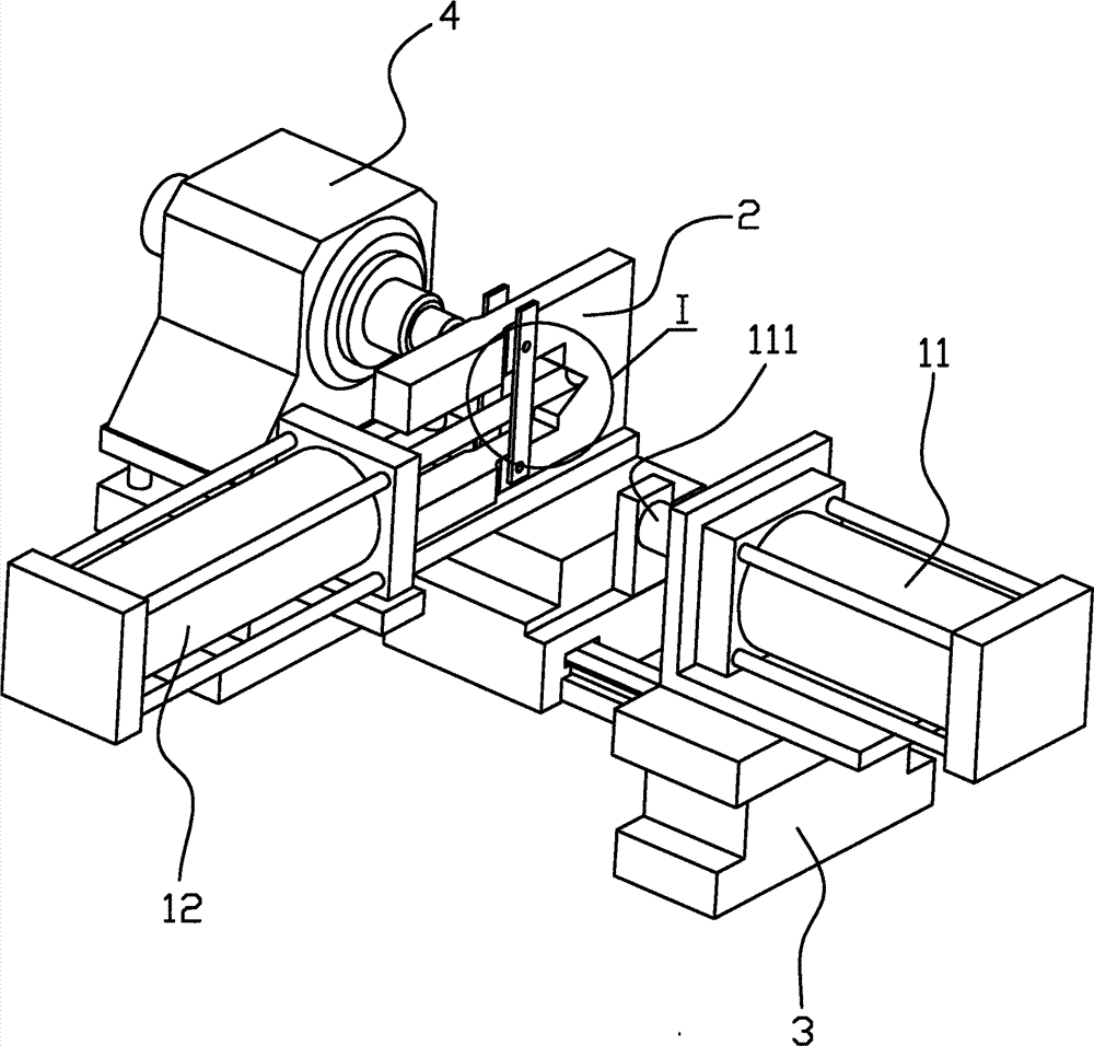
图1为本实用新型实施例的结构示意图;Fig. 1 is the structural representation of the utility model embodiment;
图2为图1中的I部的放大图;Fig. 2 is the enlarged view of part I in Fig. 1;
图3为图1中的另一状态的结构示意图;Fig. 3 is a schematic structural diagram of another state in Fig. 1;
图4为图3中的II部的放大图。FIG. 4 is an enlarged view of part II in FIG. 3 .
具体实施方式 Detailed ways
以下结合附图实施例对本实用新型作进一步详细描述。The utility model is described in further detail below in conjunction with the accompanying drawings.
如图1至4所示,本自动夹固螺丝的倒角装置,包括有能在机床3的滑槽上来回滑行的定位架2,以及可转动的与电机4的输出轴相联动的刀具5,定位架2与固定在机床3上的气缸一11的第一伸缩杆111相连接,在定位架2上横向设置有用于倒角定位的夹槽21,夹槽21中的螺丝的轴心线与刀具5的轴心线位于同一直线上,与定位架2滑行的水平横向方向设置有能将置于夹槽21中的螺丝自动夹住和松开的装置。As shown in Figures 1 to 4, the chamfering device for automatic clamping screws includes a
上述自动夹住和松开的装置的具体结构为:在夹槽21位置设置有第二伸缩杆121以及能使第二伸缩杆121侧向伸入夹槽21顶住或松开螺丝的气缸二12。第二伸缩杆121与气缸二12的连接杆相连接。第二伸缩杆121的前端设置有能适配螺丝的V形凹槽。The specific structure of the above-mentioned automatic clamping and loosening device is as follows: a second
工作原理:启动电机4,刀具5开始转动,将螺丝放入夹槽21的前端,气缸二12开始工作,将第二伸缩杆121推动到夹槽21的前端位置,第二伸缩杆121和定位架2将螺丝夹紧,此时手可移开;接着气缸一11开始工作,通过第一伸缩杆111推动定位架2向电机4方向滑动,刀具5对螺丝进行倒角;当倒角完毕后,气缸一11再次通过第一伸缩杆111使定位架2往回滑动,同时气缸二12使第二伸缩杆121向反方向收缩,螺丝可移出。Working principle: Start the
Claims (4)
Priority Applications (1)
| Application Number | Priority Date | Filing Date | Title |
|---|---|---|---|
| CN2012200545264U CN202490979U (en) | 2012-02-17 | 2012-02-17 | Chamfering device capable of automatically claming screw |
Applications Claiming Priority (1)
| Application Number | Priority Date | Filing Date | Title |
|---|---|---|---|
| CN2012200545264U CN202490979U (en) | 2012-02-17 | 2012-02-17 | Chamfering device capable of automatically claming screw |
Publications (1)
| Publication Number | Publication Date |
|---|---|
| CN202490979U true CN202490979U (en) | 2012-10-17 |
Family
ID=46997222
Family Applications (1)
| Application Number | Title | Priority Date | Filing Date |
|---|---|---|---|
| CN2012200545264U Expired - Lifetime CN202490979U (en) | 2012-02-17 | 2012-02-17 | Chamfering device capable of automatically claming screw |
Country Status (1)
| Country | Link |
|---|---|
| CN (1) | CN202490979U (en) |
Cited By (4)
| Publication number | Priority date | Publication date | Assignee | Title |
|---|---|---|---|---|
| CN103406596A (en) * | 2013-08-08 | 2013-11-27 | 江苏中伟业通讯设备有限公司 | Automatic chamfering unit for C-shaped clamps |
| CN103722244A (en) * | 2013-11-14 | 2014-04-16 | 苏州昌飞自动化设备厂 | Working steps of sound guide tube chamfering machine |
| CN103722245A (en) * | 2013-11-14 | 2014-04-16 | 苏州昌飞自动化设备厂 | Telescopic chamfering device for sound guide tube chamfering machine |
| CN114260509A (en) * | 2021-11-25 | 2022-04-01 | 东台立一工业技术有限公司 | Workpiece outer working surface chamfering device for sliding bearing production and processing |
-
2012
- 2012-02-17 CN CN2012200545264U patent/CN202490979U/en not_active Expired - Lifetime
Cited By (5)
| Publication number | Priority date | Publication date | Assignee | Title |
|---|---|---|---|---|
| CN103406596A (en) * | 2013-08-08 | 2013-11-27 | 江苏中伟业通讯设备有限公司 | Automatic chamfering unit for C-shaped clamps |
| CN103406596B (en) * | 2013-08-08 | 2016-12-28 | 江苏中伟业通讯设备有限公司 | C-type clamp tool automatic chamfering device |
| CN103722244A (en) * | 2013-11-14 | 2014-04-16 | 苏州昌飞自动化设备厂 | Working steps of sound guide tube chamfering machine |
| CN103722245A (en) * | 2013-11-14 | 2014-04-16 | 苏州昌飞自动化设备厂 | Telescopic chamfering device for sound guide tube chamfering machine |
| CN114260509A (en) * | 2021-11-25 | 2022-04-01 | 东台立一工业技术有限公司 | Workpiece outer working surface chamfering device for sliding bearing production and processing |
Similar Documents
| Publication | Publication Date | Title |
|---|---|---|
| CN203330718U (en) | Rapid spiral clamping device | |
| CN103624603A (en) | Double-direction eccentric clamping device | |
| CN203449042U (en) | Novel magnetic flat pliers | |
| CN205394058U (en) | a mechanical clamp | |
| CN103567960B (en) | Pin pulling device | |
| CN201931368U (en) | Jaw vice | |
| CN204657901U (en) | The holding device of bath water pipe automatically processing device | |
| CN203901142U (en) | Simple inner open file size positioning jig | |
| CN203611034U (en) | Double-head turning and rotating clamp | |
| CN201760677U (en) | Semi-automatic threading machine | |
| CN203076928U (en) | Fixture assembly | |
| CN202147069U (en) | Linear cutting fixture | |
| CN210937878U (en) | A material holding device for a wire welding machine | |
| CN203266181U (en) | Clamp capable of performing clamping fast | |
| CN201283527Y (en) | Universal feed gear for bearing grinding machine | |
| CN203371298U (en) | Inner hole machining device of diesel engine cylinder liner | |
| CN203592191U (en) | Bench clamp | |
| CN205566031U (en) | Automatic motor threading device | |
| CN202963655U (en) | Automatic orifice flatting machine for reducing pipe hoops | |
| CN204183056U (en) | A kind of building water pipe installation die head threading machine | |
| CN203414618U (en) | Cable-stripping device in cable-stripping machine | |
| CN204183292U (en) | A kind of processing tool of microphone joint cadmia | |
| CN205255147U (en) | Manual tooth machine of beating | |
| CN204053523U (en) | A kind of short shaft diameter is to boring grab | |
| CN202239666U (en) | Cutter frame for processing grooves of tile cover thrush plate |
Legal Events
| Date | Code | Title | Description |
|---|---|---|---|
| C14 | Grant of patent or utility model | ||
| GR01 | Patent grant | ||
| CX01 | Expiry of patent term | ||
| CX01 | Expiry of patent term |
Granted publication date: 20121017 |