CN202147069U - Linear cutting fixture - Google Patents
Linear cutting fixture Download PDFInfo
- Publication number
- CN202147069U CN202147069U CN201120201754U CN201120201754U CN202147069U CN 202147069 U CN202147069 U CN 202147069U CN 201120201754 U CN201120201754 U CN 201120201754U CN 201120201754 U CN201120201754 U CN 201120201754U CN 202147069 U CN202147069 U CN 202147069U
- Authority
- CN
- China
- Prior art keywords
- set screw
- grip block
- block
- utility
- model
- Prior art date
- Legal status (The legal status is an assumption and is not a legal conclusion. Google has not performed a legal analysis and makes no representation as to the accuracy of the status listed.)
- Expired - Fee Related
Links
Images

Abstract
The utility model discloses a linear cutting fixture, which comprises a clamping block and a combining block. A positioning groove is arranged at the lower end of the clamping block, a first regulating screw is arranged on one side of the clamping block horizontally, one end of the first regulating screw is positioned in the positioning groove and butted against a workpiece, the other end of the first regulating screw is positioned on the outside of the clamping block, and the combining block is connected with the clamping block fixedly in an adjustable manner by the aid of two second regulating screws which are arranged vertically. The linear cutting fixture can be used for clamping workpieces in different sizes and is convenient for processing and simple in operation.
Description
Technical field
The utility model relates to a kind of line and cuts anchor clamps.
Background technology
It is according to the design of the workpiece processed that general line cuts anchor clamps, and workpiece that can't the clamping different size runs into the workpiece of processing different size; Will thread-changing cut anchor clamps, cause inconvenient operation, clamping accurately simultaneously; Cause machining accuracy not high, and increased cost.
Summary of the invention
In order to overcome above-mentioned defective, the utility model provides a kind of simple in structure, easy to operate line to cut anchor clamps.
The utility model for the technical scheme that solves its technical problem and adopt is: a kind of line cuts anchor clamps; Include grip block and binding block; The grip block lower end is provided with locating slot, and grip block one side has been horizontally disposed with first set screw, and first set screw, one end is positioned at locating slot and pushes against workpiece; The first set screw other end is positioned at the grip block outside, and binding block is fixedly connected with grip block is adjustable through two second set screw that vertically are provided with.
The beneficial effect of the utility model is: the workpiece of clamping different size is easy to operate through regulating set screw for the utility model, has increased machining accuracy greatly, has also reduced cost simultaneously.
Description of drawings
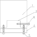
Fig. 1 is the front view of the utility model;
Fig. 2 is the right view of the utility model;
Indicate among the figure: 1-grip block, 2-binding block, 3-locating slot, 4-first set screw, 5-second set screw.
The specific embodiment
In order to deepen understanding to the utility model, will combine embodiment and accompanying drawing that the utility model is done further to detail below, this embodiment only is used to explain the utility model, does not constitute the qualification to the utility model protection domain.
Fig. 1 and Fig. 2 have shown a kind of embodiment that the utility model a kind of line cuts anchor clamps; The purpose of the utility model realizes through following case: a kind of line cuts anchor clamps, includes grip block 1 and binding block 2, and grip block 1 lower end is provided with locating slot 3; Grip block 1 one sides have been horizontally disposed with first set screw 4; First set screw, 4 one ends are positioned at locating slot 3 and push against workpiece, and first set screw, 4 other ends are positioned at grip block 1 outside, and binding block 2 is through two second set screw 5 and grip block 1 adjustable fixed connection that vertically are provided with; Can come the workpiece of the different sizes of clamping with second set screw 5 through controlling first set screw 4; Increased machining accuracy, thereby provided cost savings, convenient and simple.
Claims (1)
1. a line cuts anchor clamps; It is characterized in that: include grip block (1) and binding block (2); Said grip block (1) lower end is provided with locating slot (3); Grip block (1) one side has been horizontally disposed with first set screw (4); Said first set screw (4) one ends are positioned at locating slot (3) and push against workpiece, and first set screw (4) other end is positioned at grip block (1) outside, and said binding block (2) is through two second set screw (5) and adjustable fixed connection of grip block (1) that vertically are provided with.
Priority Applications (1)
| Application Number | Priority Date | Filing Date | Title |
|---|---|---|---|
| CN201120201754U CN202147069U (en) | 2011-06-16 | 2011-06-16 | Linear cutting fixture |
Applications Claiming Priority (1)
| Application Number | Priority Date | Filing Date | Title |
|---|---|---|---|
| CN201120201754U CN202147069U (en) | 2011-06-16 | 2011-06-16 | Linear cutting fixture |
Publications (1)
| Publication Number | Publication Date |
|---|---|
| CN202147069U true CN202147069U (en) | 2012-02-22 |
Family
ID=45588144
Family Applications (1)
| Application Number | Title | Priority Date | Filing Date |
|---|---|---|---|
| CN201120201754U Expired - Fee Related CN202147069U (en) | 2011-06-16 | 2011-06-16 | Linear cutting fixture |
Country Status (1)
| Country | Link |
|---|---|
| CN (1) | CN202147069U (en) |
Cited By (2)
| Publication number | Priority date | Publication date | Assignee | Title |
|---|---|---|---|---|
| CN107014540A (en) * | 2017-06-12 | 2017-08-04 | 苏州宝兴电线电缆有限公司 | A kind of device for testing tensile force |
| CN112676119A (en) * | 2020-12-14 | 2021-04-20 | 铜陵精远线模有限责任公司 | Split type painting die and splicing type painting die clamp for processing painting die |
-
2011
- 2011-06-16 CN CN201120201754U patent/CN202147069U/en not_active Expired - Fee Related
Cited By (2)
| Publication number | Priority date | Publication date | Assignee | Title |
|---|---|---|---|---|
| CN107014540A (en) * | 2017-06-12 | 2017-08-04 | 苏州宝兴电线电缆有限公司 | A kind of device for testing tensile force |
| CN112676119A (en) * | 2020-12-14 | 2021-04-20 | 铜陵精远线模有限责任公司 | Split type painting die and splicing type painting die clamp for processing painting die |
Similar Documents
| Publication | Publication Date | Title |
|---|---|---|
| CN105108532A (en) | Mechanical clamping device | |
| CN203459862U (en) | Tool clamp for processing clamp spring grooves of two earholes of weld yoke/shaft yoke | |
| CN202894831U (en) | Hexagonal dedicated bench clamp used for milling | |
| CN203076956U (en) | Drilling positioning device | |
| CN202147069U (en) | Linear cutting fixture | |
| CN104708148A (en) | Use method of linear cutting and positioning fixture | |
| CN204019220U (en) | Batch machining hydraulically operated fixture | |
| CN202964063U (en) | Linear cutting V-shaped groove positioning clamp of cylinder workpiece | |
| CN202292187U (en) | Clamping device of sawing machine | |
| CN104708150A (en) | Use method of locating fixture for columnar workpiece linear cutting | |
| CN203993239U (en) | Cylindrical work flank hole fixture | |
| CN203765122U (en) | Check ring assembly line cutting clamp | |
| CN202539971U (en) | Tool for cutting elbow in toothless saw | |
| CN204209244U (en) | A kind of peripheral band nibs cutting clamper | |
| CN103658897B (en) | Linear cut frock | |
| CN202894809U (en) | Valve block clamping tool | |
| CN103009077A (en) | V-shaped groove positioning clamp for wire cutting of cylindrical workpiece | |
| CN203371298U (en) | Inner hole machining device of diesel engine cylinder liner | |
| CN103273348A (en) | Clamp for processing connection rod combination surface of engine | |
| CN203527097U (en) | Linear cutting clamp for workpiece with multi-T-shaped groove | |
| CN201841484U (en) | Portable workpiece clamp head | |
| CN207914734U (en) | The anti-suspension clamp for machining of wire cutting | |
| CN202572144U (en) | Sound control tube cutting fixture | |
| CN207386751U (en) | A kind of fixture that equipment cooperation 3R fixture clamping parts are cut for line | |
| CN207696103U (en) | A kind of extrusion die inserted block skewed slot processing and loading clamp alignment device |
Legal Events
| Date | Code | Title | Description |
|---|---|---|---|
| C14 | Grant of patent or utility model | ||
| GR01 | Patent grant | ||
| C17 | Cessation of patent right | ||
| CF01 | Termination of patent right due to non-payment of annual fee |
Granted publication date: 20120222 Termination date: 20130616 |