The high-melting metal arc spraying mould is made equipment fast
Technical field
The utility model relates to the manufacturing equipment of the fast mould shell in the advanced manufacturing field, and particularly a kind of high-melting metal arc spraying mould is made equipment fast.
Background technology
The metal arc spraying rapid die-manufacturing technology is a kind of mold making technology based on " replica "; It with a mock-up (or being called prototype) as master mold; With electric arc is thermal source,, and makes its injection, is deposited on the master mold surface the atomizing of the metal material of molten condition through high velocity air; Form certain thickness compact metal shell, i.e. the mould shell.The mould shell has accurately copied the shape of prototype, has obtained required mold cavity, after accomplishing aftertreatment technologys such as reinforcement, the demoulding, polishing, can accomplish the quick manufacturing of mould.The manufacturing of electric arc spraying mould generally no longer needs additional machining after accomplishing, and just can directly be used for being shaped making.Also can carry out the numerical control fine finishining of few cutting output according to actual conditions and needs, therefore, the electric arc spraying mold making technology comes down to a kind of " near-net-shape mold making technology ".
The metal spraying mould is standard with the master mold, and mold cavity size, geometric accuracy depend on master mold fully, and mold cavity surface and meticulous decorative pattern thereof once form simultaneously; So molding speed is fast, the manufacturing cycle is short, and cost is low; Have long die life simultaneously; Manufacturing cycle is about the half the of traditional digital control processing, and manufacturing expense can be saved more than 25% at least, becomes the important channel of new product development and small lot batch manufacture.Mold surface finish is good; Technology is simple; Equipment requirements is low; Relatively be suitable for the quick manufacturing of injection mold, compression mod, sheet-metal press working mould, complicated and have in blowing, plastic uptake, PVC injection, PU foaming and all kinds of injecting molding die of the various polyurethane products of meticulous decorative pattern in surface configuration, the characteristic details that decorative pattern duplicates even can reach 5 μ m.
This fast mould manufacturing technology has been widely used in industries such as aircraft, automobile, household electrical appliances, furniture, shoemaking, artistic handicraft using at present.In the U.S. and coastal area of southeastern China, manufacturer has all adopted the electric arc spraying mould to produce on its automatic moulding production equipment at the bottom of nearly all polyurethane shoe.In automobile making, can be used for producing control wheel, automobile instrument panel, cushion, head cushion, spoiler, automotive trim ceiling etc.In recent years; The electric arc spraying mold making technology has begun to be used to make stamping die of automotive covering part; Sprayed on material is different, and intensity, hardness, precision and the life-span of spraying mould also are not quite similar, thereby range of application also there are differences; The trial-production that is suitable for the automobile sample car that has, have in addition can on production line, substitute traditional steel mold and produce.
At home; The material of spraying molding mainly is middle low-melting-point metal; Xi'an Communications University and Yantai Machinery Technology Inst. are domestic research and development unit the earliest; Advanced manufacturing technology research institute of Xi'an Communications University; Since the nineties, technology for quickly manufacturing models such as surface forming mold making technology, low-melting alloy cast molding mold making technology and resin mould mold making technology have been carried out long term studies and practice, and (the ZL200810232335.0 that on metal spraying by electric arc moulding Rapid tooling, has patent of invention; ZL03134501.8).Drag in ChangAn Automobile, Luoyang one, on enterprise application such as marine suitable, the little vapour in Liuzhou.Through trial-production check, the 3D data of qualified fast mould are used for making producing in enormous quantities use steel mold, can avoid in the design of steel mold and makes repeatedly, guarantees that the steel mold time processing is successful.
The metal wire material that is used for electric arc spraying process can be divided into low melting material, fusing point material and materials with high melting point according to the height of fusing point.When making fast mould with arc spraying technology; The thickness of die cavity metal shell will be more than 3mm; After depositing on the master mold, the molten metal particles of middle and high fusing point can discharge more heat transfer; Make master mold generation thermal deformation, reduced the accuracy of repetition of mold cavity, and possibly cause metal coating that warpage or cracking just take place when not reaching required thickness as yet; Low-melting-point metal or alloy wire are little to the heat affecting of master mold, can alleviate the influence of molten metal particles to master mold, reduce the master mold thermal deformation, improve the precision of mould, thereby low melting materials such as zinc, babbit are used for the making of fast mould morely.But the die life of this low melting material is lower; Can only be used for the small lot trial production; If will improve the life-span of spraying mould, can on master mold, spray the hear resistance of one deck low melting material with the enhancing master mold and then spray steel or the higher alloy of other intensity earlier; With the intensity of enhancing mould, thus the life-span of improving mould.
The arc spraying technology of high-melting-point, high hardness material is realized than being easier on metal mother, but at the surperficial mfg. moulding die shell of nonmetal master mold, is had big difficulty on the technology.For example; Refractory metal such as carbon steel, steel alloy when spraying shell shrinkage factor, thermal stress, porosity all bigger; Shell is easy to crack, warpage, peel off, and the mould shell is made difficulty, and technological parameter control is difficult to grasp; Distortion of mould shell and internal stress are all bigger, can't satisfy the commercial production needs.
The metal coating of making high-melting-point, high rigidity can not rely on hand spray to realize; The temperature etc. of kinematic parameter, electric arc spraying process parameter and the coating and the matrix of nozzle all need accurately be controlled according to specific target in the spraying mould making process, and intelligent arc spraying system is the basic assurance that realizes high-melting-point, high rigidity metal arc spraying rapid die-manufacturing.
Patent of invention " a kind of high-melting metal arc spraying rapid die-manufacturing method (patent No. is: ZL200810232335.0) " has just been introduced the shape and size of confirming mother plate substrate according to the shape and size of product; Make no roasting ceramic female die matrix with the refractory ceramics raw material; To the master mold surface,, nozzle can be moved and the spraying effect through electric arc spraying refractory metal molten drop 3Cr13 martensitic stain less steel along the mother plate substrate contour shape according to design parameter; Spray to the other end from an end of master mold; Repeat such process, reach 10~20mm, obtain the metal shell of master mold up to spray-on coating thickness.As for the structure of the workbench that carries mother plate substrate and movement characteristic, drive power head structure that nozzle moves and motion mode and workbench and whether master mold had heating properties and all do not do detailed introduction and explanation; Patent of invention " metal spraying by electric arc make fast car panel die special purpose robot (patent No. is: ZL03134501.8) " discloses a kind of metal spraying by electric arc fast mould manufacturing special purpose robot who is used to make stamping die of automotive covering part; This robot is integrated with electric arc spraying and two kinds of technologies of brush plating; The artificial five degree of freedom cartesian co-ordinate type of machine structure; Detent mechanism adopts planer type structure; Have three one-movement-freedom-degrees and be used to realize to spray/space orientation of brush plating operating point, wrist has two rotational freedoms, is used for the adjustment of the spatial attitude of nozzle or brush pen; Wrist portion is divided into two parallel-crank mechanisms, realizes the decoupling zero of rotational freedom and one-movement-freedom-degree.The characteristics of this robot be with lathe bed, column, crossbeam as support unit, form the finished surface track of nozzle according to the series connection kinematic principle of X, Y, the stack of Z coordinate motion, add up but the kinematic accuracy of this serial machine people nozzle is the simple linearity of each moving link; Therefore kinematic accuracy is low, poor reliability, and controlling organization is complicated; Complex structure; Weight is big, and the degree of modularity is not high, has seriously restricted applying of large complicated mould quick manufacturing process.
The utility model content
The utility model provides a kind of high-melting metal arc spraying mould to make equipment fast to the deficiency that prior art high-melting metal arc spraying rapid die-manufacturing technology exists, and it is rational in infrastructure, and is easy to use, and the degree of modularity is high, and cost is low.
For realizing above-mentioned purpose, the utility model adopts following technical scheme:
A kind of high-melting metal arc spraying mould is made equipment fast; It is provided with horizontal guide rail; The upright guide rail bottom is movably arranged on the horizontal guide rail through horizontal slide plate; The movable vertical slide plate of installing in the upright guide rail side, vertical slide plate and workbench link are connected, and corresponding linear motor all is housed between horizontal slide plate and horizontal guide rail, vertical slide plate and the upright guide rail; The workbench link is provided with six-freedom worktable; Said six-freedom worktable is provided with the two degrees of freedom yaw, and said two degrees of freedom yaw comprises the servo-hydraulic motor, and the servo-hydraulic motor is connected with the yaw swing span through connector; The yaw swinging axle is installed on the yaw swing span; The yaw swinging axle is connected with the servo force torque motor, and the servo force torque motor is installed on the yaw swing span, and shower nozzle is installed on the yaw swinging axle; Servo force torque motor, servo-hydraulic motor, each linear motor all are connected with the control computer.
The link of said servo-hydraulic motor is connected with the six degree of freedom platform through flange; The output axle head of servo-hydraulic motor has one section threaded interior hole; Connector is connected with the output shaft of servo-hydraulic motor; The connector other end is connected the as a whole consolidation structure of yaw swing span through flange with the yaw swing span; The yaw swinging axle is hollow shaft and has keyway, and the yaw swinging axle is equipped with rolling bearing through the shaft shoulder and yaw swing span location in the outside of the shaft shoulder, outside the rolling bearing bearing (ball) cover is housed, and bearing (ball) cover is connected with the yaw swing span; The adjustment packing ring is housed between bearing (ball) cover and the yaw swing span to be sealed; Middle part at the yaw swinging axle is drilled with through hole, and shower nozzle is connected through double-screw bolt with the yaw swinging axle; In a side of yaw swing span, the servo force torque motor is through being connected with the yaw swing span, and the output shaft of servo force torque motor is connected with the yaw swinging axle through key.
Said horizontal slide plate is connected with horizontal linear motor moving guide rail, and horizontal linear motor fixed guide is connected with horizontal guide rail, and horizontal linear motor moving guide rail slides on horizontal linear motor fixed guide through horizontal linear motor roller; The horizontal linear electric motor primary is connected with horizontal slide plate, and the horizontal linear motor secondary is connected with horizontal guide rail through horizontal backing plate, and the horizontal displacement measurement mechanism is housed on horizontal slide plate, and the horizontal displacement measurement mechanism is connected with the control computer.
Said workbench link is connected with vertical slide plate; Vertical slide plate is connected with vertical linear electric motors moving guide rail; Vertically the linear electric motors fixed guide is connected with upright guide rail, and vertically the linear electric motors moving guide rail is vertically sliding on the linear electric motors fixed guide through vertical linear electric motors roller; Vertically the straight line electric motor primary is connected with vertical slide plate, and vertically the straight line motor secondary is connected with upright guide rail through vertical backing plate, and the vertical displacement measurement mechanism is housed on vertical slide plate, and the vertical displacement measurement mechanism is connected with the control computer.
Said six-freedom worktable is to comprise moving platform, and fixed platform is formed with six expansion links that are connected between the two, and fixed platform is fixed on above the workbench link; Said expansion link mainly is made up of hydraulic cylinder and piston rod; Hydraulic cylinder adopts double acting band valve hydraulic cylinder; Its two ends adopt electrohydraulic servo valve to link to each other with the fluid pressure drive device of equipment, under the control computer control in hydraulic cylinder input hydraulic pressure oil with the realization actuation cycle; On hydraulic cylinder, also be provided with position-detection sensor, interrelate through external counter and control computer; The hydraulic cylinder lower end is connected through Hooke's hinge with fixed platform; The piston rod upper end is connected through universal ball joint with moving platform; Through changing the collapsing length of piston rod in six expansion links; Drive moving platform do translation, up-down, around 3-D walls and floor rotation and various compound motion, and then drive the pose location that shower nozzle realizes that six degree of freedom is complex-curved.
The fixed platform of six degree of freedom workbench is connected with the workbench link; Workbench link and vertical slide plate are connected; Vertical linear electric motors are housed between vertical slide plate and the upright guide rail; Vertical slide plate is connected with vertical straight line electric motor primary, and vertically the straight line motor secondary is connected with upright guide rail through vertical backing plate, through controlling moving up and down of vertical straight line electric motor primary; And then drive vertical slide plate, workbench link, six degree of freedom workbench integral body and move up and down at upright guide rail, realize moving along the Z traversing guide.Horizontal guide rail is equipped with the horizontal linear motor; Elementary and the horizontal slide plate of horizontal linear motor is connected; The secondary of horizontal linear motor is connected with horizontal guide rail through horizontal backing plate; Through the horizontal movement of control horizontal linear electric motor primary, and then drive horizontal slide plate, upright guide rail, the horizontal movement of six degree of freedom workbench integral body on horizontal guide rail, realize moving along the directions X guide rail.The fixed platform of six degree of freedom workbench is fixed on above the workbench link.Six expansion links are arranged between moving platform and the fixed platform; Through changing the collapsing length of piston rod in six expansion links; Drive moving platform do translation, up-down, around 3-D walls and floor rotation and various compound motion, and then drive the pose location that shower nozzle realizes that six degree of freedom is complex-curved.On the moving platform of six degree of freedom workbench, be connected with the two degrees of freedom yaw, can realize that shower nozzle is around the rotation of Y axle with around the swing of Y axle; The high-melting metal arc spraying mould is made X, the moving of Z traversing guide of equipment fast and is controlled by linear motor driving; Around the rotation of Y axle by servo-hydraulic motor drive controlling, around the swing of Y axle by servo force torque motor drive controlling, the motion of six degree of freedom workbench expansion link is controlled by hydraulic-driven.
The beneficial effect of the utility model is: compared with prior art; The utility model high-melting metal arc spraying mould is made equipment fast can realize ten free degree motions, has therefore improved the scope of application of equipment greatly, particularly is fit to the needs of full-sized car covering fast mould; The integrated degree of the utility model is high in addition; Kinematic accuracy is high, is convenient to realize automatic control, and having solved does not have large-scale ten free degree high-melting metal arc spraying moulds to make the difficult problem of equipment fast at present; Significant to commercial production, particularly auto industry is had tangible impetus.
Description of drawings
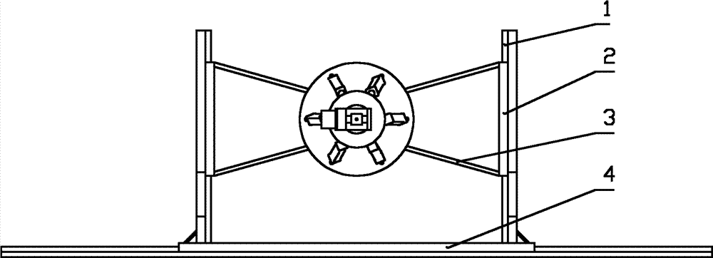
Fig. 1 makes the equipment front view fast for the high-melting metal arc spraying mould;
Fig. 2 makes the equipment vertical view fast for the high-melting metal arc spraying mould;
Fig. 3 is a six-freedom parallel motion platform front view;
Fig. 4 is the expansion link structure chart;
Fig. 5 is two degrees of freedom swing header structure figure;
Fig. 6 installs sectional view for the horizontal linear motor;
Fig. 6 a is the partial enlarged drawing of Fig. 6;
Fig. 7 is that vertical linear electric motors are installed sectional view;
Fig. 8 is vertical linear electric motors installation site figure;
Fig. 9 is expansion link control block diagram;
Figure 10 is servo-hydraulic motor control block diagram;
Figure 11 is linear electric motors control block diagram;
Figure 12 is servo force torque motor control block diagram.
Wherein, 1-upright guide rail, 2-vertical slide plate, 3-workbench link, 4-horizontal slide plate, 5-horizontal guide rail; 6-servo-hydraulic motor, 7-connector, 8-yaw swinging axle, 9-shower nozzle, 10-yaw swing span; 11-servo force torque motor, 12-moving platform, 13-universal ball joint, 14-piston rod, 15-hydraulic cylinder; The 16-Hooke's hinge, 17-fixed platform, 18-key, 19-bearing (ball) cover, 20-rolling bearing; 21-adjusts packing ring, 22-horizontal linear motor roller, the horizontal backing plate of 23-, 24-horizontal linear motor secondary, 25-horizontal linear electric motor primary; 26-horizontal linear motor fixed guide, 27-horizontal linear motor moving guide rail, 28-horizontal displacement measurement mechanism, the vertical linear electric motors moving guide rail of 29-, the vertical backing plate of 30-; The vertical straight line motor secondary of 31-, the vertical straight line electric motor primary of 32-, the vertical linear electric motors roller of 33-, the vertical linear electric motors fixed guide of 34-, 35-vertical displacement measurement mechanism.
The specific embodiment
Below in conjunction with accompanying drawing and embodiment the utility model is further specified.
Visible in conjunction with Fig. 1, Fig. 2, Fig. 6, Fig. 6 a, Fig. 7, Fig. 8, this structural entity has two upright guide rails 1 and 5. two vertical linear electric motors symmetries of two horizontal guide rails are installed between vertical slide plate 2 and the upright guide rail 1.The moving platform 12 of six degree of freedom workbench is connected with servo-hydraulic motor 6 through flange, and servo-hydraulic motor 6 output shafts are connected with yaw swing span 10 through connector 7, is connecting yaw swinging axle 8 and servo force torque motor 11 on the yaw swing span 10.The rotation through control servo-hydraulic motor 6 and the swing of servo force torque motor 11 realize the motion of two degrees of freedom yaw.The elongation of six degree of freedom workbench through control piston bar 14 with shrink control moving platform 12 do translation, up-down, around 3-D walls and floor rotation and various compound motion, so just realized that six of parallel connection platform move freely.The fixed platform 17 of six degree of freedom workbench is connected with workbench link 3 bolts; Workbench link 3 is connected with vertical slide plate 2; Between vertical slide plate 2 and the upright guide rail 1 vertical linear electric motors are housed; Vertical slide plate 2 is connected with vertical straight line electric motor primary 32 bolts; Vertically straight line motor secondary 31 is connected with upright guide rail 1 bolt through vertical backing plate 30, and through controlling moving up and down of vertical straight line electric motor primary 32, and then drive vertical slide plate 2, workbench link 3, six degree of freedom workbench integral body move up and down on upright guide rail 1.
In the center of horizontal guide rail 5 the horizontal linear motor is housed; Elementary 25 of horizontal linear motor is connected with horizontal slide plate 4 bolts; Secondary 24 of horizontal linear motor passes through horizontal backing plate 23 and is connected with horizontal guide rail 5 bolts; Through the horizontal movement of control horizontal linear electric motor primary 25, and then drive horizontal slide plate 4, upright guide rail 1, six degree of freedom workbench integral body and on horizontal guide rail 5, do horizontal movement.
Visible in conjunction with Fig. 1 and Fig. 6, Fig. 6 a; Horizontal slide plate 4 is connected with horizontal linear motor moving guide rail 27 bolts; Horizontal linear motor fixed guide 26 is connected with horizontal guide rail 5 bolts, and horizontal linear motor moving guide rail 27 slides on horizontal linear motor fixed guide 26 through horizontal linear motor roller 22.Horizontal linear motor secondary 24 is connected with horizontal backing plate 23, and horizontal backing plate 23 is connected with horizontal guide rail 5 bolts.Horizontal linear electric motor primary 25 is connected with horizontal slide plate 4 bolts, and horizontal displacement measurement mechanism 28 is housed on upright guide rail 1.Horizontal linear electric motor primary 25 is connected with horizontal slide plate 4 through bolt.
Visible in conjunction with Fig. 1, Fig. 7 and Fig. 8; Vertical slide plate 2 is connected with vertical linear electric motors moving guide rail 29 bolts; Vertically linear electric motors fixed guide 34 is connected with upright guide rail 1 bolt, and vertically linear electric motors moving guide rail 29 is vertically sliding on the linear electric motors fixed guide 34 through vertical linear electric motors roller 33.Vertically straight line motor secondary 31 is connected with vertical backing plate 30, and vertically backing plate 30 is connected with upright guide rail 1 bolt.Vertically straight line electric motor primary 32 is connected with vertical slide plate 2 bolts, and vertical displacement measurement mechanism 35 is housed on vertical slide plate 2.Vertically straight line electric motor primary 32 is connected with vertical slide plate 2 through bolt.
During linear electric motors work; In the horizontal direction; The control computer drives horizontal slide plate 4 moving in the horizontal direction through accurately moving of control horizontal linear electric motor primary 25; Horizontal slide plate 4 is connected with upright guide rail 1, and then the mobile drive upright guide rail 1 of horizontal slide plate 4 moves in the horizontal direction; In the vertical direction; The control system moves through the vertical direction that drives vertical slide plate 2 that accurately moves of controlling two vertical straight line electric motor primary 32; Workbench link 3 is connected with vertical slide plate 2, and then vertical slide plate 2 drives parallel connection platform link moving at vertical direction.
Visible in conjunction with Fig. 2 and Fig. 3, the six degree of freedom workbench is by moving platform 12, and fixed platform 17 and six expansion links are formed, and the fixed platform 17 of six degree of freedom workbench is fixed on above the workbench link.Six expansion links are arranged between moving platform 12 and the fixed platform 17.Visible in conjunction with Fig. 4; This expansion link mainly is made up of hydraulic cylinder 15 and piston rod 14; Hydraulic cylinder 15 adopts double acting band valve hydraulic cylinder; Its two ends adopt electrohydraulic servo valve to link to each other with the fluid pressure drive device of equipment, can be under the control computer control in hydraulic cylinder 15 input hydraulic pressure oil with the realization actuation cycle.On hydraulic cylinder 15, also be provided with position-detection sensor, interrelate through external counter and control computer.Hydraulic cylinder 15 lower ends are connected through Hooke's hinge 16 with fixed platform 17; Piston rod 14 upper ends are connected through universal ball joint 13 with moving platform 12; Through changing the collapsing length of piston rod 14 in six expansion links; Drive moving platform 12 do translation, up-down, around 3-D walls and floor rotation and various compound motion, and then drive the pose location that shower nozzle realizes that six degree of freedom is complex-curved.
Visible in conjunction with Fig. 2, the fixed platform 17 of six degree of freedom workbench is connected with workbench link 3 through the flange ways of connecting.
Visible in conjunction with Fig. 2 and Fig. 5; The link of servo-hydraulic motor 6 is connected with the six degree of freedom platform through flange; The output axle head of servo-hydraulic motor 6 has one section threaded interior hole; Connector 7 is connected through the output shaft of bolt and servo-hydraulic motor 6, and connector 7 other end ends are connected with yaw swing span 10 through flange.Yaw swing span 10 as a whole consolidation structures.Yaw swinging axle 8 is for hollow shaft and have keyway; Yaw swinging axle 8 is through the shaft shoulder and yaw swing span 10 location; In the outside of the shaft shoulder rolling bearing 20 is housed, bearing (ball) cover 19 is equipped with in rolling bearing 20 outsides, and bearing (ball) cover 19 is connected with yaw swing span 10 through bolt.Adjustment packing ring 21 is housed between bearing (ball) cover 19 and the yaw swing span 10 to be sealed.Middle part at yaw swinging axle 8 is drilled with through hole, and shower nozzle 9 and yaw swinging axle 8 are connected through double-screw bolt.In a side of yaw swing span 10, servo force torque motor 11 is connected with yaw swing span 10 through bolt, and the output shaft of servo force torque motor 11 is connected with yaw swinging axle 8 through key 18.
During the work of two degrees of freedom yaw; The control computer of control system is realized the positioning of rotating of two degrees of freedom swing head through the corner of control servo-hydraulic motor 6; Next control computer and realize the swing of yaw swinging axle 8 through the pendulum angle of control servo force torque motor 11; Yaw swinging axle 8 is fixed with shower nozzle 9, so drive the swing of shower nozzle 9, and then the two degrees of freedom yaw is realized whole binary motion.
Because the working range of six degree of freedom workbench is limited, when expansion link is in the greatest limit position, prevent to realize spray treatment to the complicated shape mould, thus increased mobile along X, Z traversing guide, around the rotation of Y axle with around the swing of Y axle.Therefore this high-melting metal arc spraying mould is made equipment fast and is had ten frees degree.
The high-melting metal arc spraying mould is made X, the moving of Z traversing guide of equipment fast and is controlled by linear motor driving; Around the rotation of Y axle by servo-hydraulic motor drive controlling, around the swing of Y axle by servo force torque motor drive controlling, the motion of six degree of freedom workbench expansion link is controlled by hydraulic-driven.
The course of work is following: with the threedimensional model of the master mold that will spray import in the computer; Generate the program of machining control through the analysis of computer; Distribute to the controller of each drive source then; Realize the motion of each moving component, synthetic through motion then, realize the motion of six-freedom degree and the moving of two frees degree moving along upright guide rail 1, horizontal guide rail 5 of moving platform 12; The one degree of freedom motion of servo-hydraulic motor 6 rotations, the motion of the one degree of freedom of yaw swinging axle 8 swings.
Visible in conjunction with Fig. 9, the motion control process of expansion link is following: the single kinematic parameter that the control computer distributes is given the controller of this power source, and the signal that controller sends is through the D/A conversion; Send into electrohydraulic servo valve; The motion of control expansion link is sent pulse signal into counter through the monitoring of the position-detection sensor on the hydraulic cylinder 15, and the count value in the counter is sent into the control Computer Analysis afterwards; Motion next time is compensated, realize accurately moving in the position of expansion link.
Visible in conjunction with Figure 10; The motion control process of servo-hydraulic motor 6 is following: the single kinematic parameter that the control computer distributes is given the controller of this power source; The signal that controller sends is sent into electrohydraulic servo valve through the D/A conversion, the motion of control servo-hydraulic motor 6; Monitoring through the angle detecting sensor on the servo-hydraulic motor 6 is sent pulse signal into counter; Count value in the counter is sent into the control Computer Analysis afterwards, and motion next time is compensated, and realizes that the corner of hydraulic motor accurately moves.
Visible in conjunction with Figure 11; The motion control process of three linear electric motors is following: the single kinematic parameter that the control computer distributes is given PCI drive controlling card; The signal that control card sends is sent into drive circuit through conversion, and drive circuit sends and drives the accurate displacement movement of each linear electric motors of signal controlling.Horizontal linear electric motor primary 25 is connected with horizontal slide plate 4, and horizontal slide plate 4 is connected with upright guide rail 1, so the motion of horizontal linear electric motor primary 25 can drive the precise displacement motion in the horizontal direction of horizontal slide plate 4, upright guide rail 1; Two vertical straight line electric motor primary 32 are connected with vertical slide plate 2; Vertical slide plate 2 is connected with workbench link 3, so the motion of vertical straight line electric motor primary 32 can drive the precise displacement motion of vertical slide plate, workbench link 3 whole in the vertical directions.
Visible in conjunction with Figure 12; The single kinematic parameter that the control computer distributes is given controller, and controller is given driver element after changing signal, is controlled the motion of servo force torque motor 11 then by driver element; The monitoring of the velocity sensor of process servo force torque motor 11; Measured velocity information is fed back to controller,, motion next time is revised by the motion compensation quantity of next pulse of controller analysis.