CN202490696U - Cyclone dust collector - Google Patents
Cyclone dust collector Download PDFInfo
- Publication number
- CN202490696U CN202490696U CN2012201080283U CN201220108028U CN202490696U CN 202490696 U CN202490696 U CN 202490696U CN 2012201080283 U CN2012201080283 U CN 2012201080283U CN 201220108028 U CN201220108028 U CN 201220108028U CN 202490696 U CN202490696 U CN 202490696U
- Authority
- CN
- China
- Prior art keywords
- dust collector
- material layer
- cooling water
- temperature
- porous medium
- Prior art date
- Legal status (The legal status is an assumption and is not a legal conclusion. Google has not performed a legal analysis and makes no representation as to the accuracy of the status listed.)
- Expired - Lifetime
Links
Images


Landscapes
- Cyclones (AREA)
Abstract
本实用新型公开了一种旋风除尘器,包括壳体和设置于壳体上的进气口和出气口,关键在于:壳体的分离区内表面设置有多孔介质材料层,多孔介质材料层内部开有槽形冷却水道,冷却水从多孔介质材料层内部渗出,保持多孔介质材料层表面的湿润。本实用新型既能防止高温含尘气体对除尘器本体结构的损坏,又能有效除去气体中的高温颗粒,特别适合于高温含尘煤气的防爆除尘和高温条件下对细微颗粒的分离。
The utility model discloses a cyclone dust collector, which comprises a shell and an air inlet and an air outlet arranged on the shell. A groove-shaped cooling water channel is provided, and the cooling water seeps out from the inside of the porous medium material layer to keep the surface of the porous medium material layer wet. The utility model can not only prevent the high-temperature dust-containing gas from damaging the body structure of the dust collector, but also effectively remove high-temperature particles in the gas, and is especially suitable for explosion-proof dust removal of high-temperature dust-containing gas and separation of fine particles under high-temperature conditions.
Description
技术领域 technical field
本实用新型涉及一种高温除尘器。 The utility model relates to a high-temperature dust collector. the
背景技术 Background technique
在化工、石油、冶金、电力及其它行业中,常产生高温含尘气体。由于节能减排的需要,需对高温含尘气体进行除尘。在高温条件下,由于湿度大幅度下降,细小颗粒的凝聚能力大幅度降低,因此,在高温条件下对细微颗粒的分离十分困难。另外,高温时,采用的设备材质,结构形式以及热膨胀等工程问题往往影响设备的有效运行。 In chemical industry, petroleum, metallurgy, electric power and other industries, high temperature dusty gas is often produced. Due to the need for energy saving and emission reduction, it is necessary to dedust the high temperature dusty gas. Under high temperature conditions, due to the drastic drop in humidity, the coagulation ability of fine particles is greatly reduced. Therefore, it is very difficult to separate fine particles under high temperature conditions. In addition, at high temperatures, engineering issues such as equipment materials, structural forms, and thermal expansion often affect the effective operation of equipment.
中国专利文献公开号为CN 101259453A的专利公开了一种高温旋风除尘器,其内部采用砌筑耐火砖及镶嵌耐磨衬板来实现耐高温耐磨的目的,并在下部灰仓设蛇形水冷管使粉尘下降到一定的温度,便于灰层的排出。该专利主要解决高温除尘问题,依靠耐火砖及镶嵌耐磨衬板实现除尘器本体的耐高温耐磨损,水冷管设置在灰仓下部,仅对除尘器已经捕集的粉尘进行降温,与传统旋风除尘器的除尘效率类似。 The Chinese patent literature publication number is CN 101259453A, which discloses a high-temperature cyclone dust collector, which uses masonry refractory bricks and inlaid wear-resistant lining boards to achieve high-temperature and wear-resistant purposes, and a snake-shaped water cooling system is installed in the lower ash bin. The pipe makes the dust drop to a certain temperature, which is convenient for the discharge of the ash layer. This patent mainly solves the problem of high-temperature dust removal, relying on refractory bricks and inlaid wear-resistant lining boards to realize the high-temperature and wear-resistant dust collector body, and the water-cooled pipe is set at the lower part of the ash bin to cool down the dust that has been collected by the dust collector, which is different from the traditional The dust removal efficiency of the cyclone dust collector is similar.
中国专利文献公开号为CN 101559307A的专利公开了一种可以在300-1000℃工况下连续运行的耐高温除尘器,采用金属过滤筒替代布袋过滤筒以耐高温,该除尘器具有除尘效率高、运行阻力和能耗低的特点,但其金属过滤筒由耐高温金属材料制成,价格昂贵,极大的增加了除尘器的成本。 The Chinese patent publication number is CN 101559307A, which discloses a high-temperature-resistant dust collector that can operate continuously at 300-1000 ° C. It uses a metal filter cartridge instead of a bag filter cartridge to withstand high temperatures. The dust collector has high dust removal efficiency. , running resistance and low energy consumption, but the metal filter cartridge is made of high temperature resistant metal material, which is expensive and greatly increases the cost of the dust collector.
实用新型内容 Utility model content
本实用新型的目的是提供一种除尘效率高的耐高温的旋风除尘器。 The purpose of the utility model is to provide a high temperature resistant cyclone dust collector with high dust removal efficiency.
为了实现上述目的,采用以下技术方案: In order to achieve the above purpose, the following technical solutions are adopted:
一种旋风除尘器,包括壳体和设置于壳体上的进气口和出气口,其特征在于:壳体下部的分离区内表面设置有多孔介质材料层,多孔介质材料层内部开有槽形冷却水道,冷却水从多孔介质材料层内部渗出,保持多孔介质材料层表面的湿润。 A cyclone dust collector, comprising a shell and an air inlet and an air outlet arranged on the shell, characterized in that: the inner surface of the separation area at the lower part of the shell is provided with a porous medium material layer, and the porous medium material layer has a groove inside A cooling water channel is formed, and the cooling water seeps out from the inside of the porous medium material layer to keep the surface of the porous medium material layer wet.
为了防止除尘器外壳温度过高,减少高温气体能量损失,所述进气口、出气口和除尘器下部内衬有耐火材料层。 In order to prevent the temperature of the shell of the dust collector from being too high and reduce the energy loss of the high-temperature gas, the air inlet, the gas outlet and the lower part of the dust collector are lined with a refractory material layer.
为了防止气流激起灰斗内的粉尘,所述除尘器底部设置有排灰口,在排灰口的上部设置有导流装置。 In order to prevent the airflow from stirring up the dust in the ash hopper, the bottom of the dust collector is provided with an ash discharge port, and a flow guiding device is provided at the upper part of the ash discharge port.
为了方便调节冷却水量,连接槽型冷却水道的管道上设置有阀门。 In order to adjust the cooling water volume conveniently, valves are arranged on the pipes connecting the trough-type cooling water channels. the
本实用新型可以在除尘器内表面形成薄液膜,增加了除尘器内湿度,提高了细小颗粒的凝聚能力,有效抑制二次扬尘效应,利于灰尘颗粒的捕集,使得除尘效率大幅度提高,传统旋风除尘器的除尘效率一般为50~60%,本实用新型的除尘效率可达90%以上;同时在除尘器内表面形成薄液膜,还可以冷却含尘气体中的高温颗粒,当含尘气体为煤气时,可防止高温颗粒引发的煤气爆炸;另外,在除尘器内表面形成薄液膜,还可以保护除尘器本体不受高温含尘气体的冲击,对除尘器本体形成有效的冷却,最后,本实用新型不使用耐高温金属材料,制造成本较低。 The utility model can form a thin liquid film on the inner surface of the dust collector, increase the humidity inside the dust collector, improve the coagulation ability of fine particles, effectively suppress the secondary dust effect, facilitate the collection of dust particles, and greatly improve the dust removal efficiency. The dust removal efficiency of the traditional cyclone dust collector is generally 50-60%, and the dust removal efficiency of the utility model can reach more than 90%. At the same time, a thin liquid film is formed on the inner surface of the dust collector, which can also cool high-temperature particles in the dust-containing gas. When the dust gas is gas, it can prevent the gas explosion caused by high-temperature particles; in addition, a thin liquid film is formed on the inner surface of the dust collector, which can also protect the dust collector body from the impact of high-temperature dust-containing gas and form an effective cooling for the dust collector body. , Finally, the utility model does not use high-temperature-resistant metal materials, and the manufacturing cost is relatively low.
附图说明 Description of drawings
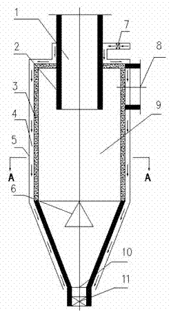
图1为本实用新型的结构示意图; Fig. 1 is the structural representation of the utility model;
图2为图1中A-A的剖面图。 Fig. 2 is a sectional view of A-A in Fig. 1 .
图中,件1为出气口;件2为耐火材料层;件3为多孔介质材料层;件4为槽形冷却水道;件5为壳体;件6为导流装置;件7为冷却水系统阀门;件8为进气口;件9为分离区;件10为排灰口;件11为排灰口阀门 。
In the figure,
具体实施方式 Detailed ways
下面结合附图和具体实施例对本实用新型加以详细描述。 Below in conjunction with accompanying drawing and specific embodiment the utility model is described in detail.
如图1和图2所示,一种旋风除尘器,包括设置有进气口8和出气口1的壳体5,其中进气口沿壳体切向设置,出气口位于壳体轴线上,即切线进气、中心出气。多孔介质材料层3安装固定在壳体5上,多孔介质材料层3靠近壳体一侧加工有槽形冷却水道4,在槽形冷却水道中通冷却水。冷却水通过毛细力作用从多孔介质材料层表面渗出,保持多孔介质材料层内表面始终处于湿润状态。当旋风除尘器在处理高温含尘气体时,气体从进气口沿切线方向进入到除尘器内部。一方面,在离心力的作用下,高温固体颗粒被甩向旋风除尘器的筒壁,与筒壁多孔介质材料层表面的冷却水充分接触,通过高温固体颗粒与冷却水间的蒸发换热,达到捕集粉尘颗粒并降低高温颗粒温度的目的,捕集的颗粒在重力作用下沿圆锥段进入到集灰斗内;部分汽化的水蒸气进入旋风除尘器内部,适当的增加了烟气中颗粒的湿度,提高了细小颗粒的凝聚能力,有助于颗粒除尘效率特别是微细粉尘的除尘效率的提高。在这个过程中可以通过冷却水系统阀门7来调节冷却水的用量,防止多孔介质材料层内表面过湿或过干。另一方面,净化后的高温气流在碰到导流装置6后旋转向上,经过出气口1排出除尘器。
As shown in Figures 1 and 2, a cyclone dust collector includes a housing 5 provided with an
Claims (5)
Priority Applications (1)
| Application Number | Priority Date | Filing Date | Title |
|---|---|---|---|
| CN2012201080283U CN202490696U (en) | 2012-03-21 | 2012-03-21 | Cyclone dust collector |
Applications Claiming Priority (1)
| Application Number | Priority Date | Filing Date | Title |
|---|---|---|---|
| CN2012201080283U CN202490696U (en) | 2012-03-21 | 2012-03-21 | Cyclone dust collector |
Publications (1)
| Publication Number | Publication Date |
|---|---|
| CN202490696U true CN202490696U (en) | 2012-10-17 |
Family
ID=46996940
Family Applications (1)
| Application Number | Title | Priority Date | Filing Date |
|---|---|---|---|
| CN2012201080283U Expired - Lifetime CN202490696U (en) | 2012-03-21 | 2012-03-21 | Cyclone dust collector |
Country Status (1)
| Country | Link |
|---|---|
| CN (1) | CN202490696U (en) |
Cited By (3)
| Publication number | Priority date | Publication date | Assignee | Title |
|---|---|---|---|---|
| CN102553734A (en) * | 2012-03-21 | 2012-07-11 | 中冶赛迪工程技术股份有限公司 | Cyclone dust collector |
| CN107694774A (en) * | 2017-11-08 | 2018-02-16 | 江苏鑫德龙环保科技有限公司 | A kind of cyclone dust collectors |
| CN111569537A (en) * | 2020-05-12 | 2020-08-25 | 宁波锦心节能环保科技有限公司 | Cyclone dust removal method |
-
2012
- 2012-03-21 CN CN2012201080283U patent/CN202490696U/en not_active Expired - Lifetime
Cited By (3)
| Publication number | Priority date | Publication date | Assignee | Title |
|---|---|---|---|---|
| CN102553734A (en) * | 2012-03-21 | 2012-07-11 | 中冶赛迪工程技术股份有限公司 | Cyclone dust collector |
| CN107694774A (en) * | 2017-11-08 | 2018-02-16 | 江苏鑫德龙环保科技有限公司 | A kind of cyclone dust collectors |
| CN111569537A (en) * | 2020-05-12 | 2020-08-25 | 宁波锦心节能环保科技有限公司 | Cyclone dust removal method |
Similar Documents
| Publication | Publication Date | Title |
|---|---|---|
| CN104399607B (en) | A kind of cyclone separator and the cyclone separation system based on the device | |
| CN201921616U (en) | Cyclone dust removal device for high-temperature high-concentration gas | |
| CN101732928A (en) | Waste gas-dust separator for cement kiln head and waste gas-dust separation method thereof | |
| CN104474825B (en) | Multi-tube high temperature electromagnetic floating bed dust collector | |
| CN104028052A (en) | Air purification device | |
| CN102553734A (en) | Cyclone dust collector | |
| CN202490696U (en) | Cyclone dust collector | |
| CN201316679Y (en) | Thermophoresis-type cyclone separator for superfine particles | |
| CN202146697U (en) | High temperature flue gas foam ceramic rotary dust collector | |
| CN108088224A (en) | A kind of biomass powder drying device | |
| CN210410057U (en) | Tail gas treatment device of chemical vapor deposition furnace | |
| CN202316145U (en) | Air-cooled type cyclone dust collector | |
| CN201046419Y (en) | Constant temperature cyclone dust extractor | |
| CN205095545U (en) | Dust recovery device of self -cleaning inner wall | |
| CN107166972A (en) | A kind of anti-clogging accumulation of heat heat release integrated device suitable for smelting furnace | |
| CN101732932A (en) | Rigid filter dust collector with uniform axial flow speed | |
| CN206660776U (en) | Water-cooled cyclone dust collector | |
| CN201658894U (en) | A cement kiln exhaust gas dust separator | |
| CN203170448U (en) | High-efficiency heat pipe heat-exchange type cyclone dust collector | |
| CN111643968A (en) | A centrifugal soot separation device | |
| CN217794609U (en) | Oil-gas separation device | |
| CN107158819B (en) | A self-cleaning flue gas dust removal device and method | |
| CN108479273A (en) | Cleaner and dust pelletizing system | |
| CN204787864U (en) | Nickel ore shaft kiln tail gas discharging equipment | |
| CN203886316U (en) | Gas purification equipment |
Legal Events
| Date | Code | Title | Description |
|---|---|---|---|
| C14 | Grant of patent or utility model | ||
| GR01 | Patent grant | ||
| CX01 | Expiry of patent term |
Granted publication date: 20121017 |
|
| CX01 | Expiry of patent term |