A kind of novel medical transfer car
Technical field
This utility model belongs to a kind of old people of lower limb disability or special-purpose assistive device that the lower limb disability personage uses of being used for, and relates in particular to a kind of medical transfer car that hospital, the home for the aged and family use that is suitable for.
Background technology
For the old people of lower limb disability, with its immigration or shift out wheelchair, domestic do not have a special equipment, the method that will adopt manpower to assist by the nursing staff usually, the effort of taking a lot of work.The external transfer car that adopts special use; Under the situation that the nursing staff assists, the hand-held handle that shifts car of old man, foot are stepped on and are shifted on the car; Stand to from wheelchair by upper limbs force then and shift in the car; The nursing staff will shift angle of car rotation, and the old man just can sit on the bed or in the dining chair, alleviate nursing staff's labor intensity then.
For the structural design of special use transfer car, key technology point is on the structure of rotating base.The external steel plate compacting base that adopts, structure is light and handy, and is in light weight.Owing to adopt the steel plate punching structure to need large-scale pressing equipment and particular manufacturing craft; Pressing equipment and particular manufacturing craft development cost are high; Enterprise just can be profitable after the quantity of product only reached certain scale, and this project organization is fit to the mode of production that external cost of labor is high, automaticity is high.And at home, because cost of labor is cheap, automaticity is low, adopts machined piece lower than the cost that adopts stamping parts on the contrary.
The utility model content
This utility model problem to be solved is to the deficiency in the background technology, proposes a kind of novel, simple in structure, medical transfer car that part is few, to adapt to the present manufacturing characteristics of China.
Adopt following technical scheme in order to solve the problems of the technologies described above: a kind of novel medical transfer car; Mainly form by last support component, rotating base component and three parts of brake component; Last support component lower end and rotating base component are fixed, and the rotating base component is provided with the brake component, and the rotating base component comprises upper bed-plate and lower bottom base; Upper bed-plate and lower bottom base link together through axis, pressing plate and screw, are provided with thrust bearing between upper bed-plate and the lower bottom base; Brake gear comprises the service brake plate, goes up pin and following pin, setting pressure spring between last pin and the following pin, and following pin upper end is provided with little pin, is arranged with the thrust spring that matches with it on the little pin.
The edge of described upper bed-plate and lower bottom base is respectively equipped with recessed edge and the flange that matches, and leaves certain clearance between recessed edge and the flange.
Thrust spring is under free state, and following pin is in and lifts the position.
Following pin is movably arranged in the pin-and-hole of top bottom-disc, and the upper end of last pin is fixed on service brake plate lower surface.
The lower bottom base side is provided with roller.
This utility model can satisfy the requirement of domestic medium and small enterprise, and process equipment is simple, and number of parts is few, material and low cost of manufacture, less demanding to workman's manufacturing and assembling level.By this utility model, the nursing staff can shift the old people or the lower limb disability personage of lower limb disability between wheelchair, bed and dining chair easily.
Description of drawings
Fig. 1 is the front view of this utility model.
Fig. 2 is the left view of Fig. 1.
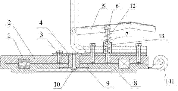
Fig. 3 is the structural representation of this utility model rotating base component and brake component.
The specific embodiment
Like Fig. 1, shown in 2; A kind of novel medical transfer car; Mainly form by last support component 001, rotating base component 002 and 003 3 parts of brake component; Through bolt, rotating base component 002 is provided with brake component 003 between last support component lower end 001 and the rotating base component 002.
As shown in Figure 3, the rotating base component comprises upper bed-plate 2 and lower bottom base 8; Upper bed-plate 2 links together through axis 4, pressing plate 9 and screw 10 with lower bottom base 8; The upper end of axis 4 is designed with step; Upper bed-plate 2 and the relative position of lower bottom base 8 have been limited along the Y axle; Leave certain clearance between axis and the lower bottom base lower surface, it is smooth and easy to move each other with assurance, no frictional resistance; Be provided with thrust bearing 1 between upper bed-plate 2 and the lower bottom base 8, with the resistance of reducing friction; The edge of upper bed-plate 2 and lower bottom base 8 is respectively equipped with recessed edge and the flange that matches, and has limited upper bed-plate and lower bottom base at X, and the relative position on the Y axle leaves certain clearance between recessed edge and the flange; Lower bottom base 8 sides are provided with roller 11.Brake gear comprises service brake plate 5, goes up pin 6 and following pin 7; Following pin 7 is movably arranged in the pin-and-hole of top bottom-disc 2; The upper end of last pin is fixed on service brake plate lower surface; Setting pressure spring 12 between last pin 6 and the following pin 7, following pin 7 upper ends are provided with little pin, are arranged with the thrust spring 13 that matches with it on the little pin.Thrust spring 13 is under free state, and following pin is in the position of lifting, and disengages with the friction surface of lower bottom base; Pin adopts the cast iron manufacturing, and wearability is good, and machinability is good, makes and change cheap.
The material of upper and lower base is a casting pig, and wearability is good, machining property is good, and all polishes smooth at its possible contact surface, imposes lubricating oil or grease, even therefore both contacts also can guarantee to rotate smooth and easy.
Operation principle: the nursing staff holds the handle that shifts car, and it is tilted, and utilizes the roller on the rotating base component, will shift car and be pushed into by the dining chair.Then the old man is pushed into wheelchair and shifts by the car.Nursing staff's tight service brake plate that tramps with one's feet earlier prevents that the rotating base component from rotating.Old man's both feet step down on the rotating base component, hold tight transfer handlebar, stand up by upper limbs force.After waiting to stand firm, the nursing staff unclamps the service brake plate, and the old man is rotated to the dining chair place, and then slams the service brake plate, lets the back old man sit down.The nursing staff pushes away away the transfer car.
During brake, the service brake plate moves downward, and promotes to go up pin downwards, simultaneously the compaction pressure spring.Continue descendingly, last pin promotes that pin is descending down, compresses thrust spring simultaneously, makes play the pin lower end contact and compress with the lower bottom base upper surface, through the frictional force between pin lower surface and the lower bottom base upper surface is locked with upper and lower base down, and the realization brake.