CN202414238U - Screw rod adjusting device guided by idler wheel - Google Patents
Screw rod adjusting device guided by idler wheel Download PDFInfo
- Publication number
- CN202414238U CN202414238U CN2011204917384U CN201120491738U CN202414238U CN 202414238 U CN202414238 U CN 202414238U CN 2011204917384 U CN2011204917384 U CN 2011204917384U CN 201120491738 U CN201120491738 U CN 201120491738U CN 202414238 U CN202414238 U CN 202414238U
- Authority
- CN
- China
- Prior art keywords
- screw rod
- fixed
- driving chain
- crossbeam
- adjusting device
- Prior art date
- Legal status (The legal status is an assumption and is not a legal conclusion. Google has not performed a legal analysis and makes no representation as to the accuracy of the status listed.)
- Expired - Fee Related
Links
Images
Landscapes
- Transmission Devices (AREA)
Abstract
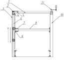
The utility model relates to a screw rod adjusting device guided by an idler wheel. The structure of the screw rod adjusting device guided by the idler wheel is as follows: the upper end of each screw rod is fixed in a stand column shell through a bearing fixing block; the lower ends of the two screw rods are suspended and are not fixed; a transmission chain wheel is mounted at the upper end of each screw rod and a chain is sleeved on the two transmission chain wheels; a transmission cover covers the upper ends of the two stand column shells and is fixed; the stand column shell at one side is provided with a rotatable handle which is inserted into the transmission chain wheel at the same side to drive the transmission chain wheel; a screw rod nut is sleeved on each screw rod, and a slide body is arranged on each screw rod nut; each of two ends of a cross beam is connected with a connecting block through a cross beam fixing block; two connecting blocks are respectively connected with the slide bodies in the two stand column shells; each slide body is provided with four central shafts and each central shaft is provided with a rolling bearing; and each rolling bearing is provided with a pulley wheel. The screw rod adjusting device guided by the idler wheel has the advantages of reasonable structure, reliable performance, good guiding effect and convenience for operation, and can accurately and efficiently carry out screw rod adjusting work.
Description
Technical field
The utility model belongs to the package packing machine field, relates to universaling packing equipment is regulated required screw mandrel control apparatus to specification, is specifically related to a kind of screw mandrel control apparatus of roller guiding.
Background technology
The universaling packing specification of equipment is regulated required screw mandrel control apparatus and is had many uses.Great majority are used for the packaging facilities of manufacturing line; Because of being used in different markets; The frequent change of manufacturing line material specification, the part body of equipment need change necessarily to specification to be regulated, and the screw mandrel control apparatus is the simplest, practical mechanism in this type of is used.But in the application of reality, some equipment are because of the requirement of structure and size, general device be directed to guide rail or guide rod, such is directed in mechanism's assembling and the field application and has point of instability, and certain requirement on machining accuracy is arranged.Such installs often screw mandrel and regulates smooth and easyly inadequately, and perhaps excessive clearance under the situation smoothly rocks because of the increase of the weight of packing materials can make fixed mechanism produce.
Summary of the invention
The purpose of the utility model does not receive the restriction of mechanism size for the use that makes the screw mandrel control apparatus; Solving screw mandrel regulates smooth and easy inadequately or excessive clearance under the situation smoothly; Fixed mechanism can produce the phenomenon of rocking, and under the prerequisite that does not improve tooling cost, a kind of screw mandrel control apparatus of roller guiding is provided; Can solve the problem in the field application effectively, the screw mandrel control apparatus is better used and use.The utility model is rational in infrastructure, dependable performance, easy and simple to handle, can satisfy the specification regulatory demand of packing mechanical equipment accurately and efficiently.
The technical scheme of the utility model is:
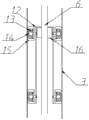
The screw mandrel control apparatus of roller guiding comprises transmission cover plate, two driving chain wheels, two root post housings, two bearing fixing pieces, chain, two rhizoid bars, two crossbeam fixed blocks, crossbeam, two contiguous blocks, rotating handles, two slide masses, eight antifriction-bearing boxs, eight center shafts, eight pulleys, two feed screw nuts; Every rhizoid bar upper end is fixed in the column housing through a bearing fixing piece; The unsettled nothing in the lower end of two screw mandrels is fixed; A driving chain wheel is installed in the upper end of every rhizoid bar, and chain is enclosed within on two driving chain wheels, and the transmission cover plate covers in two root post housings upper end and fixing; And a rotating handles wherein is installed on the column housing of a side, and rotating handles inserts the interior driving chain wheel that drives of driving chain wheel of this side; It is characterized in that: be with a feed screw nut on every rhizoid bar, each feed screw nut go up to install a slide mass, and through the rotation of screw mandrel, the feed screw nut can slide up and down, and slide mass also can up-and-down movement; The crossbeam two ends link together through a crossbeam fixed block and a contiguous block respectively, two contiguous blocks respectively with two root post housings in slide mass link to each other; Four center shafts are installed respectively on each slide mass, an antifriction-bearing box is installed on every center shaft, a pulley is installed on each antifriction-bearing box,, play the effect of guiding through the slip of pulley in two root post inner walls.
The mechanism that needs to regulate can be fixed on the crossbeam, through rotating rotating handles, can the mechanism that regulate be carried out up-and-down movement, reaches the demand of adjusting position.
The utility model is with the guiding mechanism that forms screw mandrel that slides up and down of track adjusting wheel; And application-orientedly take turns adjustable range in the screw mandrel both sides; The gap adjustment that makes screw mandrel and feed screw nut is to best, thus the phenomenon that minimizing causes the difficult and heavy back of the adjusting mechanism of screw mandrel to be rocked because of processing.
The utility model is rational in infrastructure, dependable performance, guide effect are good, easy and simple to handle, can carry out screw mandrel accurately and efficiently and regulate operation.
Description of drawings
Fig. 1 is the structural representation of the utility model.
Fig. 2 is the roller guide frame scheme drawing of the utility model.
The specific embodiment
In conjunction with the accompanying drawings the utility model is further described.
As shown in Figure 1, the utility model.
Like Fig. 1, shown in Figure 2; The utility model comprises transmission cover plate 1, two driving chain wheels 2, two root post housings (3,10), two bearing fixing pieces 4, chain 5, two rhizoid bars 6, two crossbeam fixed blocks 7, crossbeam 8, two contiguous blocks 9, rotating handles 11, two slide masses 12, eight antifriction-bearing boxs 13, eight center shafts 14, eight pulleys 15, two feed screw nuts 16; Every rhizoid bar 6 upper ends are fixed in the column housing through a bearing fixing piece 4, and the unsettled nothing in the lower end of two screw mandrels 6 is fixed, and a driving chain wheel 2 is installed in the upper end of every rhizoid bar 6; Chain 5 is enclosed within on two driving chain wheels 2, and transmission cover plate 1 covers in two root post housings (3,10) upper end and fixing; And a rotating handles 11 wherein is installed on the column housing 10 of a side, and is driven driving chain wheels 2 in the driving chain wheel 2 of rotating handles 11 these sides of insertion, it is characterized in that: be with a feed screw nut on every rhizoid bar; Each feed screw nut goes up a slide mass is installed; Through the rotation of screw mandrel, the feed screw nut can slide up and down, and slide mass also can up-and-down movement; The crossbeam two ends link together through a crossbeam fixed block and a contiguous block respectively, two contiguous blocks respectively with two root post housings in slide mass link to each other; Four center shafts are installed respectively on each slide mass, an antifriction-bearing box is installed on every center shaft, a pulley is installed on each antifriction-bearing box,, play the effect of guiding through the slip of pulley in two root post inner walls.
The mechanism that needs to regulate can be fixed on the crossbeam 8, through rotating rotating handles 11, can the mechanism that regulate be carried out up-and-down movement, reaches the demand of adjusting position.
Claims (1)
1. the screw mandrel control apparatus of roller guiding comprises transmission cover plate, two driving chain wheels, two root post housings, two bearing fixing pieces, chain, two rhizoid bars, two crossbeam fixed blocks, crossbeam, two contiguous blocks, rotating handles, two slide masses, eight antifriction-bearing boxs, eight center shafts, eight pulleys, two feed screw nuts; Every rhizoid bar upper end is fixed in the column housing through a bearing fixing piece; The unsettled nothing in the lower end of two screw mandrels is fixed; A driving chain wheel is installed in the upper end of every rhizoid bar, and chain is enclosed within on two driving chain wheels, and the transmission cover plate covers in two root post housings upper end and fixing; And a rotating handles wherein is installed on the column housing of a side, and rotating handles inserts the interior driving chain wheel that drives of driving chain wheel of this side; It is characterized in that: be with a feed screw nut on every rhizoid bar, each feed screw nut goes up a slide mass is installed; The crossbeam two ends link together through a crossbeam fixed block and a contiguous block respectively, two contiguous blocks respectively with two root post housings in slide mass link to each other; Four center shafts are installed respectively on each slide mass, an antifriction-bearing box is installed on every center shaft, a pulley is installed on each antifriction-bearing box.
Priority Applications (1)
| Application Number | Priority Date | Filing Date | Title |
|---|---|---|---|
| CN2011204917384U CN202414238U (en) | 2011-12-01 | 2011-12-01 | Screw rod adjusting device guided by idler wheel |
Applications Claiming Priority (1)
| Application Number | Priority Date | Filing Date | Title |
|---|---|---|---|
| CN2011204917384U CN202414238U (en) | 2011-12-01 | 2011-12-01 | Screw rod adjusting device guided by idler wheel |
Publications (1)
| Publication Number | Publication Date |
|---|---|
| CN202414238U true CN202414238U (en) | 2012-09-05 |
Family
ID=46739025
Family Applications (1)
| Application Number | Title | Priority Date | Filing Date |
|---|---|---|---|
| CN2011204917384U Expired - Fee Related CN202414238U (en) | 2011-12-01 | 2011-12-01 | Screw rod adjusting device guided by idler wheel |
Country Status (1)
| Country | Link |
|---|---|
| CN (1) | CN202414238U (en) |
Cited By (1)
| Publication number | Priority date | Publication date | Assignee | Title |
|---|---|---|---|---|
| CN110255154A (en) * | 2019-07-17 | 2019-09-20 | 安徽省科昌机械制造股份有限公司 | A kind of adjustable hold-down roll mechanism of overturning conveying device |
-
2011
- 2011-12-01 CN CN2011204917384U patent/CN202414238U/en not_active Expired - Fee Related
Cited By (1)
| Publication number | Priority date | Publication date | Assignee | Title |
|---|---|---|---|---|
| CN110255154A (en) * | 2019-07-17 | 2019-09-20 | 安徽省科昌机械制造股份有限公司 | A kind of adjustable hold-down roll mechanism of overturning conveying device |
Similar Documents
| Publication | Publication Date | Title |
|---|---|---|
| CN206898427U (en) | A kind of synchronous pulley drilling machine | |
| CN202783885U (en) | Crank connecting rod type drug pushing device | |
| CN208600503U (en) | A kind of volume cone machine | |
| CN102699540A (en) | Numerical control laser cutting machine | |
| CN102514882B (en) | Conveying device of medical accessories | |
| CN204658495U (en) | Linear reciprocating type medicine slicing machine | |
| CN204324260U (en) | A kind of full automaticity defoaming machine enter box guiding mechanism | |
| CN202414238U (en) | Screw rod adjusting device guided by idler wheel | |
| CN105363804A (en) | Roller gap adjusting mechanism for guiding and guarding device for rolling mill | |
| CN202481682U (en) | Single-end-lifting conveying device | |
| CN206427839U (en) | A kind of folding machine with two-fold knife structure | |
| CN204175889U (en) | A kind of speed change gear of adjustable feed length | |
| CN207131815U (en) | A kind of adjustable roller chain tension means | |
| JP6866171B2 (en) | Work transfer device | |
| CN203061736U (en) | Rear material-retaining device of computerized numerical control (CNC) bending machine | |
| CN205467386U (en) | Straight -line motion mechanism | |
| CN203003290U (en) | Tension regulation mechanism for linear cutting machine | |
| CN202727805U (en) | Tip driving device of large three-dimensional carving machine | |
| CN208496462U (en) | A kind of feed mechanism for turntable multi-angle feeding | |
| CN207997330U (en) | A kind of adjustable banding machine | |
| CN208683997U (en) | A kind of vibration aeration apparatus | |
| CN202028665U (en) | Automatic slot rolling device of processed pipe fitting | |
| CN203623038U (en) | Paperboard line pressing device | |
| CN205001466U (en) | Articulated type straight -line motion mechanism | |
| CN202271221U (en) | Horizontal processing center Y-axis dragging device |
Legal Events
| Date | Code | Title | Description |
|---|---|---|---|
| C14 | Grant of patent or utility model | ||
| GR01 | Patent grant | ||
| CF01 | Termination of patent right due to non-payment of annual fee |
Granted publication date: 20120905 Termination date: 20161201 |
|
| CF01 | Termination of patent right due to non-payment of annual fee |