CN202308923U - Insulator replacement equipment - Google Patents
Insulator replacement equipment Download PDFInfo
- Publication number
- CN202308923U CN202308923U CN201120454161XU CN201120454161U CN202308923U CN 202308923 U CN202308923 U CN 202308923U CN 201120454161X U CN201120454161X U CN 201120454161XU CN 201120454161 U CN201120454161 U CN 201120454161U CN 202308923 U CN202308923 U CN 202308923U
- Authority
- CN
- China
- Prior art keywords
- clamp plate
- insulator
- lower plate
- replacement equipment
- lower clamp
- Prior art date
- Legal status (The legal status is an assumption and is not a legal conclusion. Google has not performed a legal analysis and makes no representation as to the accuracy of the status listed.)
- Expired - Fee Related
Links
Images

Landscapes
- Insulators (AREA)
Abstract
The utility model relates to insulator replacement equipment which comprises an upper clamp plate and a lower clamp plate. A screw rod is arranged between one end of the upper clamp plate and one end of the lower clamp plate. The screw rod is rotationally connected with the lower clamp plate. The screw rod is connected with the upper clamp plate through a nut. Opening and closing ring sleeves are arranged at the other ends of the upper clamp plate and the lower clamp plate. According to the insulator replacement equipment adopting the technical scheme, an insulator string is conveniently clamped by regulating the distance between the upper clamp plate and the lower clamp plate; the opening and closing ring sleeves are used for gripping a single insulator column, so that the single zero-value or low-value insulator in NGK-160 insulators can be replaced under the charged or power outage condition; and the insulator replacement equipment has a simple structure and is convenient to use.
Description
Technical field
The utility model relates to a kind of more exchange device of insulator.
Background technology
Insulator is the critical elements of overhead transmission line, and its effect is that energized conductor and ground are kept apart effectively, makes them keep current potential separately.In service at circuit, insulator bears high pressure for a long time, and the effect of mechanical load and the variation of natural environment make it aging or damaged, cause the insulator dielectric level to descend, and threaten the safe operation of circuit.For guaranteeing the normal operation of insulator, in time changing inferior insulator becomes frequent and important work in the transmission line operation maintenance work.Existing insulator is changed instrument and is existed use inconvenience, defectives such as poor reliability mostly.
Summary of the invention
The purpose of the utility model provides more exchange device of a kind of high efficiency, insulator easy to use.
For realizing above-mentioned purpose, the utility model adopts following technical scheme:
The utility model comprises train wheel bridge and lower plate, between train wheel bridge one end and lower plate one end screw mandrel is set, and screw mandrel and lower plate are rotationally connected, and is connected through screw between screw mandrel and the train wheel bridge, at the other end of train wheel bridge and lower plate the folding ring set is set.
Described folding ring set comprises two semicircular ring, and two semicircular ring one ends are hinged, and other end bolt connects.
Top at screw mandrel is provided with handle.
Adopt the utility model of technique scheme; Through regulating the distance between train wheel bridge and the lower plate; Thereby conveniently clamp insulator string, the folding ring set is used to embrace single insulator post, thereby can under charged or power failure condition, change monolithic null value or low resistance insulator in the NGK-160 insulator; Simple in structure, easy to use.
Description of drawings
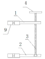
Fig. 1 is the front view of the utility model.
Fig. 2 is the vertical view of the utility model.
Embodiment
Like Fig. 1, shown in Figure 2; The utility model comprises train wheel bridge 1 and lower plate 2, between train wheel bridge 1 one ends and lower plate 2 one ends screw mandrel 3 is set, and screw mandrel 3 is rotationally connected with lower plate 2; Be connected through screw between screw mandrel 3 and the train wheel bridge 1, folding ring set 9 be set at the other end of train wheel bridge 1 and lower plate 2.Above-mentioned folding ring set 9 comprises that 5,6, two semicircular ring one ends of two semicircular ring are hinged at pin joint 8 places, and the other end connects with bolt 7.
On the top of screw mandrel 3 handle 4 is set.
The principle of the utility model is: through regulating the distance between train wheel bridge 1 and the lower plate 2; Thereby conveniently clamp insulator string; The folding ring set is used to embrace single insulator post, thereby can under charged or power failure condition, change monolithic null value or low resistance insulator in the NGK-160 insulator.
Claims (3)
1. insulator exchange device more; It is characterized in that: it comprises train wheel bridge (1) and lower plate (2); Between train wheel bridge (1) one end and lower plate (2) one ends screw mandrel (3) is set; Screw mandrel (3) and lower plate (2) are rotationally connected, and are connected through screw between screw mandrel (3) and the train wheel bridge (1), at the other end of train wheel bridge (1) and lower plate (2) folding ring set (9) are set.
2. insulator according to claim 1 is exchange device more, it is characterized in that: described folding ring set (9) comprises two semicircular ring, and two semicircular ring one ends are hinged, and other end bolt connects.
3. insulator according to claim 1 is exchange device more, it is characterized in that: on the top of screw mandrel (3) handle (4) is set.
Priority Applications (1)
| Application Number | Priority Date | Filing Date | Title |
|---|---|---|---|
| CN201120454161XU CN202308923U (en) | 2011-11-16 | 2011-11-16 | Insulator replacement equipment |
Applications Claiming Priority (1)
| Application Number | Priority Date | Filing Date | Title |
|---|---|---|---|
| CN201120454161XU CN202308923U (en) | 2011-11-16 | 2011-11-16 | Insulator replacement equipment |
Publications (1)
| Publication Number | Publication Date |
|---|---|
| CN202308923U true CN202308923U (en) | 2012-07-04 |
Family
ID=46377737
Family Applications (1)
| Application Number | Title | Priority Date | Filing Date |
|---|---|---|---|
| CN201120454161XU Expired - Fee Related CN202308923U (en) | 2011-11-16 | 2011-11-16 | Insulator replacement equipment |
Country Status (1)
| Country | Link |
|---|---|
| CN (1) | CN202308923U (en) |
Cited By (2)
| Publication number | Priority date | Publication date | Assignee | Title |
|---|---|---|---|---|
| CN109921357A (en) * | 2017-12-12 | 2019-06-21 | 镇江西杰电气有限公司 | A kind of bus-duct connector |
| CN113872111A (en) * | 2021-11-19 | 2021-12-31 | 广东电网有限责任公司 | Insulator replacement tool |
-
2011
- 2011-11-16 CN CN201120454161XU patent/CN202308923U/en not_active Expired - Fee Related
Cited By (2)
| Publication number | Priority date | Publication date | Assignee | Title |
|---|---|---|---|---|
| CN109921357A (en) * | 2017-12-12 | 2019-06-21 | 镇江西杰电气有限公司 | A kind of bus-duct connector |
| CN113872111A (en) * | 2021-11-19 | 2021-12-31 | 广东电网有限责任公司 | Insulator replacement tool |
Similar Documents
| Publication | Publication Date | Title |
|---|---|---|
| CN104535804A (en) | Portable current transformer test clamp | |
| CN202308923U (en) | Insulator replacement equipment | |
| CN202120693U (en) | Pillar type arc preventing insulator | |
| CN103245804B (en) | Assembly type inflatable high-voltage equalizing ring | |
| CN104092033A (en) | Connecting rod type thread self-locking wire end ground clamp | |
| CN202049816U (en) | Pin insulator | |
| CN204167783U (en) | Stockbridge damper resetting means in short distance | |
| CN208656288U (en) | The replacement tool of ground electrode circuit insulator and fitting | |
| CN208157161U (en) | The transmission line insulator porcelain knob of equipped wire fixing device | |
| CN203800200U (en) | Portable ground wire | |
| CN203367502U (en) | Wire grounding device | |
| CN203760919U (en) | Drainage wire bracket for live working | |
| CN202384694U (en) | Insulator replacing apparatus | |
| CN201910386U (en) | Temporary connecting device for live replacement of fuse tube of drop-out fuse | |
| CN201639196U (en) | Insulating tool set | |
| CN208955223U (en) | A kind of safe attaching/detaching apparatus of transformer grounding pole | |
| CN104092392A (en) | Alternating-current/direct-current test power source device of ultrahigh-voltage power transmission and transformation icing device | |
| CN107425466A (en) | Wire lifts insulating support and its application method | |
| CN209087470U (en) | A kind of substation's Zinc-Oxide Arrester | |
| CN106129900A (en) | A kind of vertical splitting of straight line | |
| CN202651659U (en) | Drainage apparatus capable of replacing isolating switch with load | |
| CN201774166U (en) | Capacitor bank grounding device | |
| CN103762517A (en) | High-voltage ground wire installation method | |
| CN204256030U (en) | Primary side power utility check device | |
| CN205069917U (en) | High pressure earth clamp |
Legal Events
| Date | Code | Title | Description |
|---|---|---|---|
| C14 | Grant of patent or utility model | ||
| GR01 | Patent grant | ||
| C17 | Cessation of patent right | ||
| CF01 | Termination of patent right due to non-payment of annual fee |
Granted publication date: 20120704 Termination date: 20121116 |