CN202272824U - Conveying and cleaning type double-bridge automatic glass cutting machine - Google Patents
Conveying and cleaning type double-bridge automatic glass cutting machine Download PDFInfo
- Publication number
- CN202272824U CN202272824U CN2011203902790U CN201120390279U CN202272824U CN 202272824 U CN202272824 U CN 202272824U CN 2011203902790 U CN2011203902790 U CN 2011203902790U CN 201120390279 U CN201120390279 U CN 201120390279U CN 202272824 U CN202272824 U CN 202272824U
- Authority
- CN
- China
- Prior art keywords
- frame
- conveying
- cleaning roller
- case
- belt
- Prior art date
- Legal status (The legal status is an assumption and is not a legal conclusion. Google has not performed a legal analysis and makes no representation as to the accuracy of the status listed.)
- Expired - Fee Related
Links
Images


Abstract
The utility model discloses a conveying and cleaning type double-bridge automatic glass cutting machine. The machine mainly comprises a frame (1), wherein an X beam (2) and a Y beam (3) are arranged above the frame; and each of the two beams is provided with a group of knife boxes (4). The machine is characterized in that: a supporting box (26) is arranged above the frame (1); a cleaning roller (19) is arranged between the supporting box and the frame; a driving roller (24) and a driven roller (30) are arranged at front and rear ends of the supporting box respectively; the two rollers are connected through a conveyer belt (25); and the conveyer belt covers the upper and lower end surfaces of the supporting box (26) so as to form a rotary conveying worktable. The device has the advantages that: bulk glass is not required to be manually lifted for sheet loading and unloading during cutting and can be automatically conveyed by the conveyer belt, and the conveying worktable is not required to be manually cleaned and broken glass remained on the worktable can be automatically removed in the conveying process, so that the manual work is saved and the work efficiency is improved.
Description
Technical field
The utility model relates to a kind of conveying cleaning type doube bridge Auto Glasscutter.
Background technology
At present; The doube bridge glass cutting machine is in use more adopt artificial last slice with following sheets, promptly the glass of bulk needs manual work to lift to be carried on the worktable, also needs manual work to lift from worktable after to be cut and is carried to next procedure; The glass chip that in cutting process, produces remains on the worktable; Need the workman constantly to clear up, the lost labor, production efficiency is than root.
The utility model content
The utility model designs to the shortcoming of existing doube bridge glass cutting machine, and it is provided with worktable and a cleaning roller of an automatic transport formula, and worktable and cleaning roller are synchronized with the movement.
The technical scheme of the utility model
A kind of conveying cleaning type doube bridge Auto Glasscutter mainly comprises a frame, be crisscross arranged on the frame X beam and a Y beam, and all be provided with one group of cutter box on each beam; The side of frame is provided with the driven accessary of two groups of X beams and the driven accessary of two groups of Y beams; The upper surface of frame is provided with two groups of guide rails of arranging in length and breadth; One group of two ends with the X beam is connected, and one group of two ends with the Y beam is connected, and it is characterized in that: the top of frame is provided with one and supports case; The upper surface of supporting case is uniformly distributed with venting hole, and a side that supports case is provided with an air duct; Support the rear and front end of case and respectively establish a drive roll and a driven roll, two rollers connect through a conveying belt, are uniformly distributed with the small sircle hole corresponding with the venting hole that supports case on the conveying belt, and the top and bottom that conveying belt will support case cover a revolution of formation conveying workbench; One end of drive roll is connected with power take-off mechanism; Between frame and the support case cleaning roller is set, cleaning roller cooperates with conveying belt, and an end of cleaning roller is connected with power take-off mechanism.
According to above technical scheme, following further improvement can also be arranged:
The both sides of supporting case are provided with one group of retaining plate respectively, and the lower end of each retaining plate connects a supporting studs, and supporting studs is fixedly connected with the upper surface of frame.
One end of drive roll connects a drive roll belt wheel, and the drive roll belt wheel is connected with preposition driving pulley through preposition belt, and preposition driving pulley is fixedly connected with the output terminal of motor.
One end of cleaning roller connects a cleaning roller belt wheel, and the cleaning roller belt wheel is connected with rearmounted driving pulley through rearmounted belt, and rearmounted driving pulley is fixedly connected with the output terminal of motor.
The beneficial effect of the utility model
A kind of conveying cleaning type doube bridge Auto Glasscutter; It is provided with worktable and a cleaning roller of an automatic transport formula; And worktable and cleaning roller are synchronized with the movement, and not only the glass of bulk does not need manual work to lift slice and following sheet in use, and worktable does not need manual work to clear up; Save manual work, improved working efficiency greatly.
Description of drawings
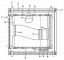
Fig. 1 is the front view of the utility model;
Fig. 2 is the vertical view of Fig. 1;
Fig. 3 is the left view of Fig. 1.
Embodiment
Like Fig. 1, shown in Figure 2; A kind of conveying cleaning type doube bridge Auto Glasscutter; It is provided with a frame 1; The below of frame connects a motor 16 and a blower fan 36, connects a preposition driving pulley 17 and a rearmounted driving pulley 35 before and after the output terminal of motor, and the air outlet of blower fan is connected with vent-pipe 37; Frame 1 is a framework that is similar to Back Word type structure, and inner framework is provided with a support table 31, and the top of support table is provided with an orthogonal and supports case 26; The two ends that an X beam 2 and 3, two beams of a Y beam are set and frame 1 are connected through annex, to upwards moving back and forth with Y, just combine concrete example at length to explain at X below.
One, housiung separator
Like Fig. 1, Fig. 2, shown in Figure 3, the bottom of frame 1 connects a motor 16 and a blower fan 36, and the upper end of frame is provided with a support table 31; An X beam 2 is set, 3, two beams of Y beam are staggered, an end of X beam raises up and is higher than the Y beam, and two beams can alternately be moved back and forth; Respectively be uniformly distributed with one group of cutter box 4 on X beam and the Y beam, and the two ends of each beam are stretched out downwards with the side of frame 1 and are connected; Four sides of frame 1 are provided with two groups of driven accessaries, and one group is the driven accessary of X beam 2, and one group is the driven accessary of Y beam 3.
A, X beam driven accessary: as shown in Figure 1, an X beam main shaft 10 is set through frame 1, its two ends are connected with frame 1 through supporting seat 12, and the end stretches out from supporting seat, and the part of stretching out respectively connects an X beam driving pulley 11; To connect an output motor in the middle of the X beam main shaft 10, to make X beam driving pulley 11 rotations (clear in order describing, motor does not draw in the drawings) at X beam main shaft 10 drive two ends; An X beam driven shaft 7 is set through frame 1, its two ends are connected with frame 1 through supporting seat 12, and the end stretches out from supporting seat, and the part of stretching out respectively connects an X beam driven pulley 8, and it is corresponding with X beam driving pulley 11; The X beam driven pulley 8 and the X beam driving pulley 11 of each group are the profile of tooth belt wheel, and they connect through cingulum in the X beam 9; The two ends of X beam 2 are fixedly connected with the correspondence position of cingulum 9 in the X beam, make the interior cingulum 9 of X beam can drive X beam 2 and on same direction, move back and forth back and forth.
B, Y beam driven accessary: as shown in Figure 3, a Y beam main shaft 13 is set through frame 1, its two ends are connected with frame 1 through supporting seat 12, and the end stretches out from supporting seat, and the part of stretching out respectively connects a Y beam driving pulley 14; To connect an output motor in the middle of the Y beam main shaft 13, to make Y beam driving pulley 14 rotations (clear in order describing, motor does not draw in the drawings) at Y beam main shaft 13 drive two ends; A Y beam driven shaft 33 is set through frame 1, its two ends are connected with frame 1 through supporting seat 12, and the end stretches out from supporting seat, and the part of stretching out respectively connects a Y beam driven pulley 32, and it is corresponding with Y beam driving pulley 14; The Y beam driven pulley 32 and the Y beam driving pulley 14 of each group are the profile of tooth belt wheel, and they connect through cingulum in the Y beam 15; The two ends of Y beam 3 are fixedly connected with the correspondence position of cingulum 15 in the Y beam, make the interior cingulum 15 of Y beam can drive Y beam 3 and on same direction, move back and forth back and forth.
C, guide rail: as shown in Figure 2, arrange four guide rails 6 on the support table 31 of frame 1 in length and breadth, the end of each guide rail is fixedly connected with support table 31 through chock 5; The two ends that per two guide rail 6 cocurrent and parallels are provided with respectively with X beam and Y beam are slidingly connected, and make X beam and Y beam back and forth to move around.
Two, support case
Like Fig. 2, shown in Figure 3; The top of support table 31 is provided with an orthogonal and supports case 26, and the upper surface of supporting case is uniformly distributed with venting hole, and a side that supports case connects an air duct 38; Air duct is connected with blower fan 36 through vent-pipe 37, when blower fan is worked, can the air that support in the case 26 be extracted out; The both sides of supporting case 26 connect the retaining plate 28 of one group of " L " type respectively; The vertical surface of retaining plate 28 is connected through bolt with the side of supporting case 26, and its horizontal plane connects a supporting studs 29, and supporting studs is fixedly connected with support table 31, with supporting the top that case 26 is fixed on support table.
Three, conveying workbench
A, like Fig. 1, shown in Figure 2, the rear and front end of supporting case 26 is provided with a drive roll 24 and a driven roll 30 respectively, the two ends of each roller all connect a permanent seat 27; Two portions before and after permanent seat 27 is divided into: the part of front is a chock, and it is connected with the end of each roller; The part of back is the permanent seat of a wedge shape, and it is connected through bolt with the correspondence position that supports case 26, and the lower end of the permanent seat of wedge shape connects a supporting studs 29, and supporting studs is fixedly connected with support table 31.
B, drive roll 24 and driven roll 30 are connected through a conveying belt 25; Be uniformly distributed with the small sircle hole corresponding on the conveying belt with the venting hole that supports case 26; And the top and bottom that conveying belt will support case 26 cover the swiveling table that forms a feeding type, and the air in supporting case can be adsorbed on glass on the worktable when being drawn out of firmly; One end of drive roll 24 connects a drive roll belt wheel 23, and it is connected with preposition driving pulley 17 through preposition belt 18, and preposition driving pulley is fixedly connected with the output terminal of motor 16.
Four, cleaning roller
A, like Fig. 1, shown in Figure 3; Between frame 1 and the support case 26 cleaning roller 19 is set; Its two ends connect a riser 22 respectively, and upper part of each riser is connected through bolt with the side of supporting case 26, and lower part of each riser connects a supporting seat 20; The two ends of cleaning roller 19 are connected with supporting seat 20, and wherein an end stretches out from supporting seat, and the end of stretching out connects a cleaning roller belt wheel 21, and cleaning roller belt wheel 21 is connected with rearmounted driving pulley 35 through rearmounted belt 34; Rearmounted driving pulley and preposition driving pulley 17 all are connected in the output terminal of motor 16, make conveying belt 25 and cleaning roller 19 to be synchronized with the movement; The cylindrical of cleaning roller 19 connects the thick felt of a circle, and cleaning roller is positioned at the below of supporting case 26, and when conveying belt and cleaning roller rotated synchronously, cleaning roller can be with glass chip cleaning residual on the conveying belt totally.
Five, working process
When the conveying workbench of cutting machine was worked, structural glass one end that needs are cut was pushed on the conveying belt of cutting machine, glass is fed forward until monolithic glass evenly contacts fully with the conveying belt worktable; Open blower fan 36 disable motors 3 this moment; Glass is adsorbed on the worktable, opens the X beam and with Y beam motor glass cutting is become set shape, X beam and Y beam quit work; Open motor 3 and close blower fan 36; Conveying belt is seen off glass evenly, and when conveying belt rotated, the cleaning roller of below was done synchronous rotation glass chip residual on the conveying belt is cleaned out automatically.
Claims (4)
1. carry cleaning type doube bridge Auto Glasscutter for one kind, mainly comprise a frame (1), be crisscross arranged on the frame X beam (2) and a Y beam (3), and all be provided with one group of cutter box (4) on each beam; The side of frame (1) is provided with the driven accessary of two groups of X beams (2) and the driven accessary of two groups of Y beams (3); The upper surface of frame (1) is provided with two groups of guide rails of arranging in length and breadth (6); One group of two ends with X beam (2) is connected; One group of two ends with Y beam (3) is connected; It is characterized in that: the top of frame (1) is provided with one and supports case (26), and the upper surface of supporting case is uniformly distributed with venting hole, and a side that supports case is provided with an air duct (38); Support the rear and front end of case (26) and respectively establish a drive roll (24) and a driven roll (30); Two rollers connect through a conveying belt (25); Be uniformly distributed with on the conveying belt and the corresponding small sircle hole of venting hole that supports case (26), the top and bottom that conveying belt will support case cover a revolution of formation conveying workbench; One end of drive roll (24) is connected with power take-off mechanism; Between frame (1) and the support case (26) cleaning roller (19) is set, cleaning roller cooperates with conveying belt (25), and an end of cleaning roller is connected with power take-off mechanism.
2. a kind of conveying cleaning type doube bridge Auto Glasscutter according to claim 1; It is characterized in that: the both sides of supporting case (26) are provided with one group of retaining plate (28) respectively; The lower end of each retaining plate connects a supporting studs (29), and supporting studs is fixedly connected with the upper surface of frame (1).
3. a kind of conveying cleaning type doube bridge Auto Glasscutter according to claim 1; It is characterized in that: an end of drive roll (24) connects a drive roll belt wheel (23); The drive roll belt wheel is connected with preposition driving pulley (17) through preposition belt (18), and preposition driving pulley is fixedly connected with the output terminal of motor (16).
4. a kind of conveying cleaning type doube bridge Auto Glasscutter according to claim 1; It is characterized in that: an end of cleaning roller (19) connects a cleaning roller belt wheel (21); The cleaning roller belt wheel is connected with rearmounted driving pulley (35) through rearmounted belt (34), and rearmounted driving pulley is fixedly connected with the output terminal of motor (16).
Priority Applications (1)
| Application Number | Priority Date | Filing Date | Title |
|---|---|---|---|
| CN2011203902790U CN202272824U (en) | 2011-10-14 | 2011-10-14 | Conveying and cleaning type double-bridge automatic glass cutting machine |
Applications Claiming Priority (1)
| Application Number | Priority Date | Filing Date | Title |
|---|---|---|---|
| CN2011203902790U CN202272824U (en) | 2011-10-14 | 2011-10-14 | Conveying and cleaning type double-bridge automatic glass cutting machine |
Publications (1)
| Publication Number | Publication Date |
|---|---|
| CN202272824U true CN202272824U (en) | 2012-06-13 |
Family
ID=46193195
Family Applications (1)
| Application Number | Title | Priority Date | Filing Date |
|---|---|---|---|
| CN2011203902790U Expired - Fee Related CN202272824U (en) | 2011-10-14 | 2011-10-14 | Conveying and cleaning type double-bridge automatic glass cutting machine |
Country Status (1)
| Country | Link |
|---|---|
| CN (1) | CN202272824U (en) |
Cited By (2)
| Publication number | Priority date | Publication date | Assignee | Title |
|---|---|---|---|---|
| CN102320729A (en) * | 2011-10-14 | 2012-01-18 | 陈邦善 | Double-bridge automatic glass cutting machine capable of cleaning glass in conveying process |
| CN105776835A (en) * | 2016-03-11 | 2016-07-20 | 东莞市银锐精密机械有限公司 | Glass slitting assembly line |
-
2011
- 2011-10-14 CN CN2011203902790U patent/CN202272824U/en not_active Expired - Fee Related
Cited By (3)
| Publication number | Priority date | Publication date | Assignee | Title |
|---|---|---|---|---|
| CN102320729A (en) * | 2011-10-14 | 2012-01-18 | 陈邦善 | Double-bridge automatic glass cutting machine capable of cleaning glass in conveying process |
| CN102320729B (en) * | 2011-10-14 | 2013-06-05 | 孟钧 | Double-bridge automatic glass cutting machine capable of cleaning glass in conveying process |
| CN105776835A (en) * | 2016-03-11 | 2016-07-20 | 东莞市银锐精密机械有限公司 | Glass slitting assembly line |
Similar Documents
| Publication | Publication Date | Title |
|---|---|---|
| CN202367813U (en) | After-loading high-speed computer cut-to-size saw | |
| CN102390063A (en) | Back loading high-speed computer panel saw | |
| CN203901430U (en) | Board cutting production line | |
| CN202825889U (en) | Poria cocos cutting machine | |
| CN101862745A (en) | Automatic cleaning device for glass | |
| CN103935821B (en) | PE gloves automatic layboys | |
| CN202272824U (en) | Conveying and cleaning type double-bridge automatic glass cutting machine | |
| CN102785287A (en) | Suspended type foamed cement plate cutting and producing system | |
| CN207027624U (en) | The vertical and horizontal cutter device of pearl cotton | |
| CN104002351B (en) | Wooden clothes tree multi-station processing equipment | |
| CN210475894U (en) | Automatic unloader that goes up of laser cutting | |
| CN102225523A (en) | Conveying system of glass edge-grinding machine | |
| CN207915674U (en) | A kind of multifunctional wood board machining production line | |
| CN102320729B (en) | Double-bridge automatic glass cutting machine capable of cleaning glass in conveying process | |
| CN206108310U (en) | A device is carried to supplementary moving of bag sealer for woodwork | |
| CN212123665U (en) | Mud material quantitative conveyor of ceramic production line | |
| CN202272825U (en) | Conveying type automatic twin-bridge glass cutting machine | |
| CN205167019U (en) | Cutting machine is synthesized to dried tofu with automatically, advance row material function | |
| CN211581457U (en) | Candy production shaping cutting device | |
| CN203665656U (en) | Wooden clothes hanger multi-station processing device | |
| CN203028011U (en) | Automatic dough feeder | |
| CN102432165A (en) | Conveying double-bridge automatic glass cutting machine | |
| CN202088049U (en) | Conveying system of glass edging machine | |
| CN204773671U (en) | LED diffuser plate production line with dust collector | |
| CN202245040U (en) | Conveying type glass unloading table |
Legal Events
| Date | Code | Title | Description |
|---|---|---|---|
| C14 | Grant of patent or utility model | ||
| GR01 | Patent grant | ||
| C17 | Cessation of patent right | ||
| CF01 | Termination of patent right due to non-payment of annual fee |
Granted publication date: 20120613 Termination date: 20121014 |