CN202269060U - Intelligent controller for solar wind energy charging and light control - Google Patents
Intelligent controller for solar wind energy charging and light control Download PDFInfo
- Publication number
- CN202269060U CN202269060U CN2011203357775U CN201120335777U CN202269060U CN 202269060 U CN202269060 U CN 202269060U CN 2011203357775 U CN2011203357775 U CN 2011203357775U CN 201120335777 U CN201120335777 U CN 201120335777U CN 202269060 U CN202269060 U CN 202269060U
- Authority
- CN
- China
- Prior art keywords
- module
- output
- charging
- storage battery
- solar
- Prior art date
- Legal status (The legal status is an assumption and is not a legal conclusion. Google has not performed a legal analysis and makes no representation as to the accuracy of the status listed.)
- Expired - Fee Related
Links
Images
Classifications
-
- Y—GENERAL TAGGING OF NEW TECHNOLOGICAL DEVELOPMENTS; GENERAL TAGGING OF CROSS-SECTIONAL TECHNOLOGIES SPANNING OVER SEVERAL SECTIONS OF THE IPC; TECHNICAL SUBJECTS COVERED BY FORMER USPC CROSS-REFERENCE ART COLLECTIONS [XRACs] AND DIGESTS
- Y02—TECHNOLOGIES OR APPLICATIONS FOR MITIGATION OR ADAPTATION AGAINST CLIMATE CHANGE
- Y02B—CLIMATE CHANGE MITIGATION TECHNOLOGIES RELATED TO BUILDINGS, e.g. HOUSING, HOUSE APPLIANCES OR RELATED END-USER APPLICATIONS
- Y02B20/00—Energy efficient lighting technologies, e.g. halogen lamps or gas discharge lamps
- Y02B20/40—Control techniques providing energy savings, e.g. smart controller or presence detection
Landscapes
- Charge And Discharge Circuits For Batteries Or The Like (AREA)
Abstract
The utility model relates to an intelligent controller for solar wind energy charging and light control, which comprises a micro control unit (MCU) control unit, a voltage measuring module and a switch module and is characterized by comprising a small-current zero-voltage-drop charging module, a constant current fast charging module and an output module. The input end and the output end of the small-current zero-voltage-drop charging module are connected with the output end of a solar panel and the input end of an input module respectively. The input end of the constant current fast charging module is connected with the output end of the solar panel and/or the output end of a wind driven generator, and the output end of the constant current fast charging module is connected with the output module. The controller achieves small-current zero-voltage-drop charging and large current constant current charging according to detected voltage, enables a charging effect to be the best, and prolongs service life of a storage battery. The controller can automatically reduce output power according to the state of the storage battery, prevents the storage battery from being in a deep discharging state, and guarantees a whole solar light-emitting diode (LED) light source system works in a positive cycle.
Description
Technical field
The utility model relates to a kind of intelligent controller that is used for solar wind-energy charging and light control; In particular, relate in particular to a kind of intelligent controller that can carry out solar wind-energy charging with the light control of little current zero pressure drop and big electric current constant current charge to storage battery.
Background technology
Along with the minimizing gradually of nonrenewable resources on the earth, the utilization of wind energy and solar energy increases gradually, especially at illumination and power field, uses more extensive.Generally speaking; Wind energy and solar energy have non-contiguity, in the center of crossing to its utilization, should be at first the electric energy discontinuous, that numerical value is non-constant that is come by wind energy or conversion of solar energy be stored; And then, reach utilizable purpose the unified release of the energy of storage.
In the system that employing solar energy or wind energy are thrown light on; Want to be stored in the electric energy of solar energy photovoltaic panel and wind-driven generator conversion in the storage battery smoothly; And throw light on it; Also to prolong the useful life of storage battery simultaneously to greatest extent, need a kind ofly to carry out the relevant parameter collection and to carry out the controller of Based Intelligent Control, but existing controller not possess intelligent control according to the data of gathering.
Summary of the invention
The utility model provides a kind of intelligent controller that is used for solar wind-energy charging and light control that can carry out little current zero pressure drop and big electric current constant current charge to storage battery in order to overcome the shortcoming of above-mentioned technical problem.
The intelligent controller that is used for solar wind-energy charging and light control of the utility model; The voltage measurement module that has comprised the MCU control unit of data operation and control action, storage battery is detected and with the direct-connected switch module of light source, its special feature is: also comprise the output module that is used for little current zero pressure drop charging module, the constant current quick charge module that storage battery is charged and is used for being connected with storage battery; The input and output side of said little current zero pressure drop charging module is connected with the output of solar panels and the input of input module respectively; The input of said constant current quick charge module all is connected with the output of solar panels with or wind-driven generator, and output is connected with output module.The MUC control unit is used for the signal of gathering is handled and calculated, and according to data and the logical relation calculated, comes peripheral module is controlled, and the MUC control unit can adopt single-chip microcomputer; Voltage measurement module is realized the measurement to outside battery tension, and switch module is used for the state of light source is directly controlled.Little current zero pressure drop charging module and constant current quick charge module can realize little electric current and constant current charge to storage battery respectively, are used in respectively under the low and normal situation of voltage of solar panels output.
The intelligent controller that is used for solar wind-energy charging and light control of the utility model; Said constant current quick charge module is made up of constant-current source, and said little current zero pressure drop charging module is by forming the gate-controlled switch of the direct electric connection of input of the output of solar panel and output module.Through adopting constant-current source, can realize quick constant current charge to storage battery; Little current zero pressure drop charging module adopts gate-controlled switch, is used for the output of solar panels is directly linked to each other with the input of output module, realizes the direct charging to storage battery.
The intelligent controller that is used for solar wind-energy charging and light control of the utility model comprises being used for lightning protection unit that solar panels and whole intelligent controller are shielded.Because solar panels are struck by lightning so that there is not the place, higher position of object around being in easily, lightning protection unit is set helps entire controller is protected.
The intelligent controller that is used for solar wind-energy charging and light control of the utility model, said MCU control unit is connected with at least two the toggle switch module that is used for the running status of controller is selected.Through two toggle switchs can realize 00,01,10, the choosing of 11 4 kind of state so that controller is operated under four kinds of different patterns.
The beneficial effect of the utility model is: the utility model is through being provided with MCU control unit, little current zero pressure drop charging module and constant current quick charge module; Realized voltage swing effectively according to solar panels output; Between little current zero pressure drop charge mode and big electric current constant current charging mode, choose; Promptly utilize solar energy to greatest extent, also protected storage battery effectively, prolonged the useful life of storage battery.Controller can reduce power output automatically according to the state of storage battery, avoids storage battery to get into the deep discharge state, at next or several charging cycle sufficient electrical energies, guarantees the work under benign cycle of whole solar energy led light-source system with the protection storage battery.
Description of drawings
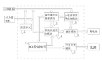
Fig. 1 is the circuit theory diagrams of the utility model.
Among the figure: 1 MCU control unit, 2 lightning protection unit, 3 voltage measurement modules, 4 constant current quick charge modules, 5 little current zero pressure drop charging modules, 6 output modules, 7 switch modules.
Embodiment
Below in conjunction with accompanying drawing and embodiment the utility model is described further.
As shown in Figure 1, provided the circuit theory diagrams of the utility model, it comprises MCU control unit 1, lightning protection unit 2, voltage measurement module 3, constant current quick charge module 4, little current zero pressure drop charging module 5, output module 6, switch module 7; Shown MCU control unit 1 is used for the output of data operation and control signal, and it can adopt single-chip microcomputer.Voltage measurement module 3 is used to realize the measurement of battery tension state, and is input to data measured in the MCU control unit 1.The gate-controlled switch that little current zero pressure drop charging module 5 can adopt control end to link to each other with MCU control unit 1 so that in the lower situation elder generation that solar panels are exported, be communicated with the output of solar panels and the input of storage battery, is realized little current zero pressure drop charging.Constant current quick charge module 4 is made up of constant-current source, when the voltage of solar panels output is higher, through the control of MCU control unit 1 storage battery is carried out the quick charge of big electric current constant current piece.The input of output module 6 is connected with the output of constant current quick charge module 4 with little current zero pressure drop charging module 5, and output is connected with storage battery.Switch module 7 is used for the connection status between storage battery and the light source is controlled through the control of MCU control unit 1.
Shown constant current quick charge module 4 also is connected with the output of wind-driven generator with the input of little current zero pressure drop charging module 5, so that under the situation that has wind-driven generator to exist, can also wind energy be stored and utilize.
The intelligent controller that is used for solar wind-energy charging and light control of the utility model can adopt following charging method; May further comprise the steps: (a). at first; Under the lower situation of solar panels output voltage; Control the charging input end that little current zero pressure drop charging module (5) directly is communicated with the output and the storage battery of solar panels through MCU control unit (1), realize little current zero pressure drop charging, play the repair of storage battery to external world storage battery; (b). then, under solar panels output voltage condition with higher, storage battery is carried out the constant current quick charge, replenish so that in the shortest time, storage battery is carried out power shortage through MCU control unit (1) control constant current quick charge module (4); (c). last, when the voltage that detects storage battery reach rated voltage 102~120% the time, it is adopted the floating charge pattern of the little current forms of constant voltage, so that when realizing charging, storage battery is protected to greatest extent.It is criterion that the voltage of exporting with solar panels in the step (a) is lower than 90% of its rated voltage; Voltage with solar panels output in the step (b) is criterion more than or equal to 90% of its rated voltage; Reaching 105% of single lattice rated voltage with the voltage of storage battery in the step (c) is criterion.
The utility model adopt artificial intelligence and charge control module according to the generating curve of solar panels to charge in batteries; Adopt the little current zero pressure drop charging of The initial segment; Can play repair to the overdischarge storage battery; Stage casing big electric current constant current quick charge replenishes to satisfy power shortage the soonest, and the control of floating charge section constant voltage makes storage battery get pole plate and realizes fully exchange.Make gas output reach minimum, make it reach the loss minimum with the protection accumulator plate.
After system powers on, detection system voltage at first, bright lamp 10 seconds; Detect the output voltage of solar panels simultaneously, to judge round the clock.When solar panels voltage is lower than 1.66V, get into bright lamp program after 15 seconds.Bright lamp program is divided into one of four states, and choosing of different conditions decides through two toggle switch states.For example:
1, toggle switch is 00 o'clock, is the construction status routine; The output of employing half-power with protection storage battery and led light source, is used for the loss of construction stage minimizing to storage battery and led light fixture.
Function: the power supply of 50% power was turn-offed after 10 hours.
2, toggle switch is 01 o'clock, is the acceptance phase program; Total power output is checked and accepted so that the light source lighting lamp state is tested.Be used for the technical checking of acceptance phase to system's solar panel, storage battery and light fixture.
Function: the power supply of 100% power was turn-offed after 10 hours.
3, toggle switch is 02 o'clock, is intelligent 1 operating state program; Under this state, with 70% power work ensuing 2 hour with full power operation more ensuing 2 hour with 70% power work to bright day turned off the light in preceding 1 hour by back half-power work for bright lamp.
The omnidistance Intelligent Measurement battery tension of controller;, overcast and rainy long voltage reduces power output when being lower than 80% rated voltage automatically; Avoid storage battery to get into the deep discharge state, make whole solar energy led light-source system get into benign cycle at next or several charging cycle sufficient electrical energies with the protection storage battery.
4, toggle switch is 11 to be to be intelligent 2 status routines; Preceding 4 hours with full power operation, half-power work in back 6 hours.The omnidistance Intelligent Measurement battery tension of controller;, overcast and rainy long voltage reduces power output when being lower than 80% rated voltage automatically; Avoid storage battery to get into the deep discharge state, make whole solar energy led light-source system get into benign cycle at next or several charging cycle sufficient electrical energies with the protection storage battery.
Claims (4)
1. one kind is used for the intelligent controller that solar wind-energy charges and light is controlled; The voltage measurement module (3) that has comprised the MCU control unit (1) of data operation and control action, storage battery is detected and with the direct-connected switch module of light source (7), it is characterized in that: also comprise the output module (6) that is used for little current zero pressure drop charging module (5), the constant current quick charge module (4) that storage battery is charged and is used for being connected with storage battery; The input and output side of said little current zero pressure drop charging module is connected with the output of solar panels and the input of input module respectively; The input of said constant current quick charge module (4) all is connected with the output of solar panels with or wind-driven generator, and output is connected with output module.
2. the intelligent controller that is used for solar wind-energy charging and light control according to claim 1; It is characterized in that: said constant current quick charge module (4) is made up of constant-current source, and said little current zero pressure drop charging module (5) is by forming the gate-controlled switch of the direct electric connection of input of the output of solar panel and output module (6).
3. the intelligent controller that is used for solar wind-energy charging and light control according to claim 1 and 2 is characterized in that: comprise being used for lightning protection unit (2) that solar panels and whole intelligent controller are shielded.
4. the intelligent controller that is used for solar wind-energy charging and light control according to claim 1 and 2, it is characterized in that: said MCU control unit (1) is connected with at least two the toggle switch module that is used for the running status of controller is selected.
Priority Applications (1)
| Application Number | Priority Date | Filing Date | Title |
|---|---|---|---|
| CN2011203357775U CN202269060U (en) | 2011-09-08 | 2011-09-08 | Intelligent controller for solar wind energy charging and light control |
Applications Claiming Priority (1)
| Application Number | Priority Date | Filing Date | Title |
|---|---|---|---|
| CN2011203357775U CN202269060U (en) | 2011-09-08 | 2011-09-08 | Intelligent controller for solar wind energy charging and light control |
Publications (1)
| Publication Number | Publication Date |
|---|---|
| CN202269060U true CN202269060U (en) | 2012-06-06 |
Family
ID=46159840
Family Applications (1)
| Application Number | Title | Priority Date | Filing Date |
|---|---|---|---|
| CN2011203357775U Expired - Fee Related CN202269060U (en) | 2011-09-08 | 2011-09-08 | Intelligent controller for solar wind energy charging and light control |
Country Status (1)
| Country | Link |
|---|---|
| CN (1) | CN202269060U (en) |
Cited By (2)
| Publication number | Priority date | Publication date | Assignee | Title |
|---|---|---|---|---|
| CN102325413A (en) * | 2011-09-08 | 2012-01-18 | 山东金世博光电工程有限公司 | The intelligent controller and the charging method that are used for solar wind-energy charging and light control |
| CN103178581A (en) * | 2013-02-27 | 2013-06-26 | 山东省科学院自动化研究所 | Electric vehicle low-voltage high-current battery pack combination device and control method |
-
2011
- 2011-09-08 CN CN2011203357775U patent/CN202269060U/en not_active Expired - Fee Related
Cited By (3)
| Publication number | Priority date | Publication date | Assignee | Title |
|---|---|---|---|---|
| CN102325413A (en) * | 2011-09-08 | 2012-01-18 | 山东金世博光电工程有限公司 | The intelligent controller and the charging method that are used for solar wind-energy charging and light control |
| CN103178581A (en) * | 2013-02-27 | 2013-06-26 | 山东省科学院自动化研究所 | Electric vehicle low-voltage high-current battery pack combination device and control method |
| CN103178581B (en) * | 2013-02-27 | 2015-04-22 | 山东省科学院自动化研究所 | Electric vehicle low-voltage high-current battery pack combination device and control method |
Similar Documents
| Publication | Publication Date | Title |
|---|---|---|
| CN202396048U (en) | Solar street lamp intelligent monitoring system based on Internet of things | |
| CN101026917B (en) | Solar LED lamp circuit | |
| CN202496116U (en) | Solar street lamp control system | |
| CN102325413A (en) | The intelligent controller and the charging method that are used for solar wind-energy charging and light control | |
| CN202713735U (en) | Multifunctional solar energy street lamp system | |
| CN202269060U (en) | Intelligent controller for solar wind energy charging and light control | |
| CN201539807U (en) | Solar alley lamp | |
| CN103024993A (en) | Energy-saving outdoor illumination controlling system and controlling method | |
| CN101660701A (en) | Wind-light complementary illuminating apparatus used for antiaircraft gun billboard | |
| CN201251081Y (en) | Wind and light complementary lighting device for high-profile billboard | |
| CN203036536U (en) | Intelligent solar street lamp | |
| CN102752935A (en) | Solar light-emitting diode (LED) lamp controller | |
| CN201866684U (en) | Solar LED (light emitting diode) aisle illumination device | |
| CN202218031U (en) | Off-grid type electric power input control system | |
| CN202094659U (en) | Solar automatic maintenance device for generator set starting batteries | |
| CN102298848A (en) | Solar LED (Light-Emitting Diode) traffic light | |
| CN202444667U (en) | Wind and solar hybrid LED (light-emitting diode) lamp control system | |
| CN203136294U (en) | A LED lamp control circuit with energy stored in a lithium battery | |
| CN203661378U (en) | Solar street lamp control device | |
| CN201779576U (en) | Solar LED street lamp | |
| CN202353899U (en) | Energy-saving environmentally-friendly street lamp | |
| CN202143257U (en) | Control system of solar energy LED lamp | |
| CN202043349U (en) | Light-emitting diode (LED) control system | |
| CN201323675Y (en) | System for controlling solar-energy street lamp | |
| CN201490748U (en) | Multifunctional controller |
Legal Events
| Date | Code | Title | Description |
|---|---|---|---|
| C14 | Grant of patent or utility model | ||
| GR01 | Patent grant | ||
| C17 | Cessation of patent right | ||
| CF01 | Termination of patent right due to non-payment of annual fee |
Granted publication date: 20120606 Termination date: 20120908 |